


 Loading...
Dell™ 2405FPW Flat Panel Monitor
About Your Monitor
Front View
Back View
Side View Bottom View
Monitor Specifications
Universal Serial Bus(USB) Interface Card Reader Specifications
Dell™ Sound Bar (Optional) Specifications Caring for Your Monitor
Using Your Adjustable Monitor Stand
Attaching the Stand
Organizing Your Cables
Using the Tilt, Swivel, Vertical Extension
Removing the Stand
Setting Up Your Monitor
Connecting Your Monitor
Using the Front Panel Buttons
Using the OSD
Setting the Optimal Resolution
Using the Dell™ Sound Bar (Optional)
Using the Card Reader
Rotating Your Monitor
Changing the Rotation of Your Monitor
Rotating Your Operating System
Solving Problems
Monitor Specific Troubleshooting
Common Problems
Video Problems
Product Specific Problems
Universal Serial Bus (USB) Specific Problems
Dell™ Sound Bar (Optional) Troubleshooting
Card Reader Troubleshooting
Appendix
Warranty Information
Safety Information
Safety Information: Card Reader
Contacting Dell™
Regulatory Notices
Your Monitor Set-up Guide
Notes, Notices, and Cautions
Throughout this guide, blocks of text may be accompanied by an icon and printed in bold type or in italic type. These blocks are notes, notices, and cautions, and they are used as follows:
NOTE: A NOTE indicates important information that helps you make better use of your computer.
NOTICE: A NOTICE indicates either potential damage to hardware or loss of data and tells you how to avoid the problem.
CAUTION: A CAUTION indicates the potential for property damage, personal injury, or death.
Some warnings may appear in alternate formats and may be unaccompanied by an icon. In such cases, the specific presentation of the caution is mandated by regulatory authority.
Information in this document is subject to change without notice. © 2005 Dell™ Inc. All rights reserved.
Reproduction in any manner whatsoever without the written permission of Dell Inc. is strictly forbidden.
Trademarks used in this text: Dell, the DELL logo, Inspiron, Dell Precision, Dimension, OptiPlex, Latitude, PowerEdge, PowerVault, PowerApp, and Dell OpenManage are trademarks of DellInc; Microsoft and Windows are registered trademarks of Microsoft Corporation; ENERGY STAR is a registered trademark of the U.S. Environmental Protection Agency. As an ENERGY STAR partner, Dell Inc. has determined that this product meets the ENERGY STAR guidelines for energy efficiency. CompactFlash is a trademark of The CompactFlash Association (CFA). Secure Digital is a trademark of The Secure Digital Association. SmartMedia is a trademark of Toshiba Corporation. MultiMediaCard is a trademark of MultiMediaCard Association. Microdrive is a trademark of International Business Machines Corporation. Memory Stick and MagicGate are trademarks of Sony Corporation.
Other trademarks and trade names may be used in this document to refer to either the entities claiming the marks and names or their products. Dell Inc. disclaims any proprietary interest in trademarks and trade names other than its own.
April 2005 Rev. A01
Back to Contents Page
About Your Monitor
Dell™ 2405FPW Flat Panel Monitor
 Front View
 Back View
 Side View
 Bottom View
 Monitor Specifications
 Universal Serial Bus(USB) Interface
 Card Reader Specifications
 Dell™ Sound Bar (Optional) Specifications
 Caring for Your Monitor
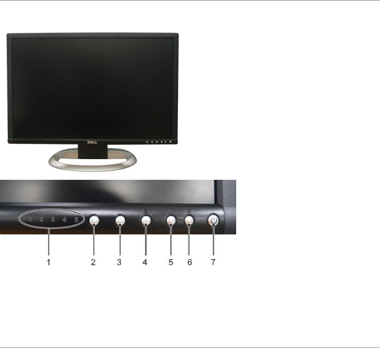
Front View
1Input indicators
2Input selection
3PIP (Picture In Picture) / PBP (Picture By Picture) selection
4Menu selection
5Brightness & Contrast / Down(-)
6Auto-Adjust / Up(+)
7Power button
Back View

1Kensington lock slot
2USB downstream ports and card reader
3Mechanical attachment point for Dell™ Sound Bar
4Cable holder
5Stand lock release button
Side View
Right side
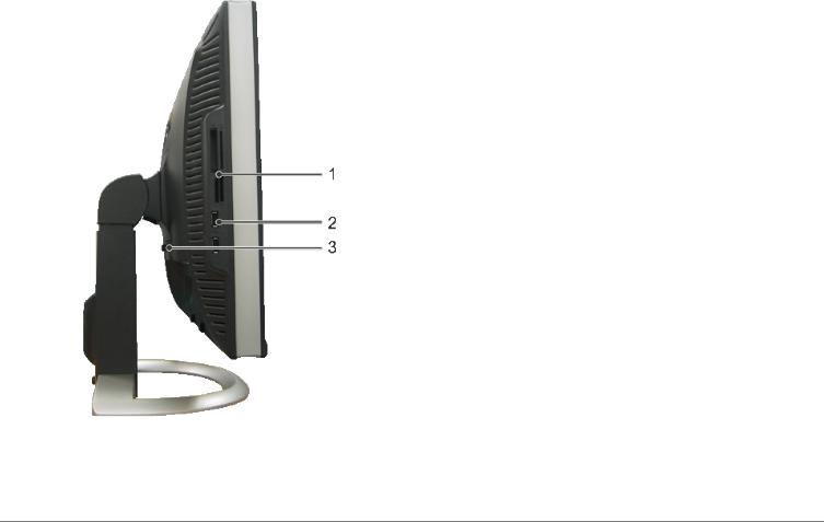
Left side
1Card reader: for details please refer to Card Reader Specifications
2USB downstream ports
3Display removal button
Bottom View
1AC power cord connector
2DC power connector for Dell™ Sound Bar
3S-Video connector
4Composite video connector
5Component video connectors
6DVI connector
7VGA connector
8USB upstream port
9USB downstream ports

Monitor Specifications
General
Model number |
2405FPW |
Flat Panel
Screen type |
Active matrix - TFT LCD |
Screen dimensions |
24 inches (24-inch diagonal viewable image size) |
Preset display area: |
|
Horizontal |
518.4 mm (20.4 inches) |
Vertical |
324.0 mm (12.7 inches) |
Pixel pitch |
0.270 mm |
Viewing angle |
+/- 89° (vertical) typ, +/- 89° (horizontal) typ |
Luminance output |
500 cd/m ²(typ) |
Contrast ratio |
1000:1 (typ) |
Faceplate coating |
Antiglare with hard-coating 3H |
Backlight |
6 CCFLs U-type backlight |
Response Time |
12ms typical (Grey to Grey) / 16ms typical (Black to White) |
Resolution
Horizontal scan range |
30 kHz to 81 kHz (automatic) |
Vertical scan range |
56 Hz to 76 Hz, exception 1680 x 1200 & 1920 x 1200 at 60 Hz |
|
only |
Optimal preset resolution |
Analog : 1920 x 1200 at 60 Hz(VESA CVT-R Mode) |
|
Digital : 1920 x 1200 at 60 Hz(VESA CVT-R Mode) |
Highest preset resolution |
Analog : 1920 x 1200 at 60 Hz(VESA CVT-R Mode) |
|
Digital : 1920 x 1200 at 60 Hz(VESA CVT-R Mode) |
Dell™ guarantees image size and centering for all preset modes listed in the following table.
Preset Display Modes
Display Mode |
Horizontal Frequency (kHz) Vertical Frequency (Hz) Pixel Clock (MHz) Sync Polarity (Horizontal/Vertical) |
VGA, 720 x 400 |
31.5 |
70.1 |
28.3 |
-/+ |
VGA, 640 x 480 |
31.5 |
59.9 |
25.2 |
-/- |
VESA, 640 x 480 |
37.5 |
75.0 |
31.5 |
-/- |
VESA, 800 x 600 |
37.9 |
60.3 |
40.0 |
+/+ |
VESA, 800 x 600 |
46.9 |
75.0 |
49.5 |
+/+ |
VESA, 1024 x 768 |
48.4 |
60.0 |
65.0 |
-/- |
VESA, 1024 x 768 |
60.0 |
75.0 |
78.8 |
+/+ |
VESA, 1152 x 864 |
67.5 |
75.0 |
108.0 |
+/+ |
VESA, 1280 x 1024 |
64.0 |
60.0 |
108.0 |
+/+ |
VESA, 1280 x 1024 |
80.0 |
75.0 |
135.0 |
+/+ |
VESA, 1600 x 1200 |
75.0 |
60.0 |
162.0 |
+/+ |
VESA, 1920 x 1200 |
74.0 |
60.0 |
154.0 |
+/- |
Electrical
Video input signals
Synchronization input signals
AC input voltage / frequency / current Inrush current
Analog RGB: 0.7 Volts +/-5%, 75 ohm input impedance Digital DVI-D TMDS: 600mV for each differential line, 50 ohm input impedance
S-video: Y input 1 volt(p-p), C input 0.286 volt(p-p), 75 ohm input impedance
Composite: 1 volt(p-p), 75 ohm input impedance, Component: Y, Pb, Pr are all 0.5~1volt(p-p), 75 ohm input impedance
separate horizontal and vertical,
3.3V Cmos or 5V TTL level, positive or negative sync. SOG (Sync on green)
100 to 240 VAC / 50 or 60 Hz + 3 Hz / 2.0A (Max.)
120V: 40A (Max.) 240V: 80A (Max.)
Physical Characteristics
Signal cable type
Dimensions (with stand):
Height (fully extended in portrait mode)
Height (compressed/locked in landscape mode)
Width
Depth
Weight
Monitor (Stand and Head)
Monitor Flat panel only (VESA Mode)
Weight with packaging
D-sub: Detachable, Analog, 15pin, shipped attached to the monitor
DVI-D: Detachable, Digital, 24pin, shipped detached from the monitor
S-video: Not included with display Composite: Not included with display Component: Not included with display
642.7 mm (25.3 inches)
546.8 mm (21.5 inches)
559.4 mm (22.0 inches)
229.0 mm (9.0 inches)
10.0 kg (22.1 lb)
7.0 kg (15.4 lb)
13.2 kg (29.1 lb)
Environmental
Temperature: |
|
Operating |
5° to 35°C (41° to 95°F) |
Nonoperating |
Storage: 0° to 60°C (32° to 140°F) |
|
Shipping: -20° to 60°C(-4° to 140°F) |

Humidity: |
|
|
Operating |
10% to 80% (noncondensing) |
|
Nonoperating |
Storage: 5% to 90% (noncondensing) |
|
|
Shipping: 5% to 90%(noncondensing) |
|
Altitude: |
|
|
Operating |
3,657.6 m (12,000 ft) max |
|
Nonoperating |
12,192 m (40,000 ft) max |
|
Thermal dissipation |
272.8 |
BTU/hour (maximum) |
|
201.2 |
BTU/hour (typical) |
Power Management Modes
If you have VESA's DPMS compliance display card or software installed in your PC, the monitor can automatically reduce its power consumption when not in use. This is referred to as 'Power Save Mode'*. If input from keyboard, mouse or other input devices is detected by the computer, the monitor will automatically "wake up". The following table shows the power consumption and signaling of this automatic power saving feature:
VESA Modes |
Horizontal Sync |
Vertical Sync |
Video |
Power Indicator |
Power Consumption |
Normal |
Active |
Active |
Active |
Green |
80 W (maximum)* |
operation |
|
|
|
|
59 W (normal)** |
Active-off mode |
Inactive |
Inactive |
Blanked |
Amber |
Less than 2 W |
Switch off |
- |
- |
- |
Off |
Less than 1 W |
|
|
|
|
|
* With Audio + USB |
|
|
|
|
|
** Without Audio + USB |
NOTE: The OSD will only function in the 'normal operation' mode. Otherwise one of the following messages will appear depending upon the selected input.
1: D-SUB |
|
2: DVI-D |
|
In Power Save Mode |
or |
In Power Save Mode |
|
Press computer power button |
Press computer power button |
||
|
|||
or any key on keyboard or move mouse |
|
or any key on keyboard or move mouse |
Activate the computer and wake up the monitor to gain access to the OSD.
Pin Assignments
VGA Connector
Pin Number |
15-pin Side of the Connected Signal Cable |
1 |
Video-Red |
2 |
Video-Green |
3 |
Video-Blue |
4 |
GND |
5 |
Self-test |
6 |
GND-R |
7 |
GND-G |
8 |
GND-B |
9 |
Computer 5V/3.3V |
10 |
GND-sync |
11 |
GND |

12 |
DDC data |
13 |
H-sync |
14 |
V-sync |
15 |
DDC clock |
DVI Connector
Pin Number |
24-pin Side of the Connected Signal Cable |
1 |
TMDS RX2- |
2 |
TMDS RX2+ |
3 |
TMDS Ground |
4 |
Floating |
5 |
Floating |
6 |
DDC Clock |
7 |
DDC Data |
8 |
Floating |
9 |
TMDS RX1- |
10 |
TMDS RX1+ |
11 |
TMDS Ground |
12 |
Floating |
13 |
Floating |
14 |
+5V / +3.3V power |
15 |
Self test |
16 |
Hot Plug Detect |
17 |
TMDS RX0- |
18 |
TMDS RX0+ |
19 |
TMDS Ground |
20 |
Floating |
21 |
Floating |
22 |
TMDS Ground |
23 |
TMDS Clock+ |
24 |
TMDS Clock- |
S-video Connector

Pin Number |
|
5-pin Side of the Connected Signal Cable (Cable not included) |
1 |
|
GND |
|
||
2 |
|
GND |
3 |
|
LUMA |
4 |
|
CHROMA |
5 |
|
GND |
Composite Video Connector
Pin Number |
1-pin Side of the Connected Signal Cable (cable not included) |
1 |
LUMA COMPOSITE CHROMA |
Component Video Connector
Pin Number |
3-pin Side of the Connected Signal Cable (Cable not |
|
included) |
1 |
Y (Luminance signal) |
2 |
Pb (Color differential signal) |
3 |
Pr (Color differential signal) |
Universal Serial Bus (USB) Interface
This monitor supports High-Speed Certified USB 2.0 interface.
|
Data Rate |
Power Consumption |
High speed |
480 Mbps |
2.5W (Max., each port) |
Full speed |
12 Mbps |
2.5W (Max., each port) |
Low speed |
1.5 Mbps |
2.5W (Max., each port) |
USB Upstream Connector
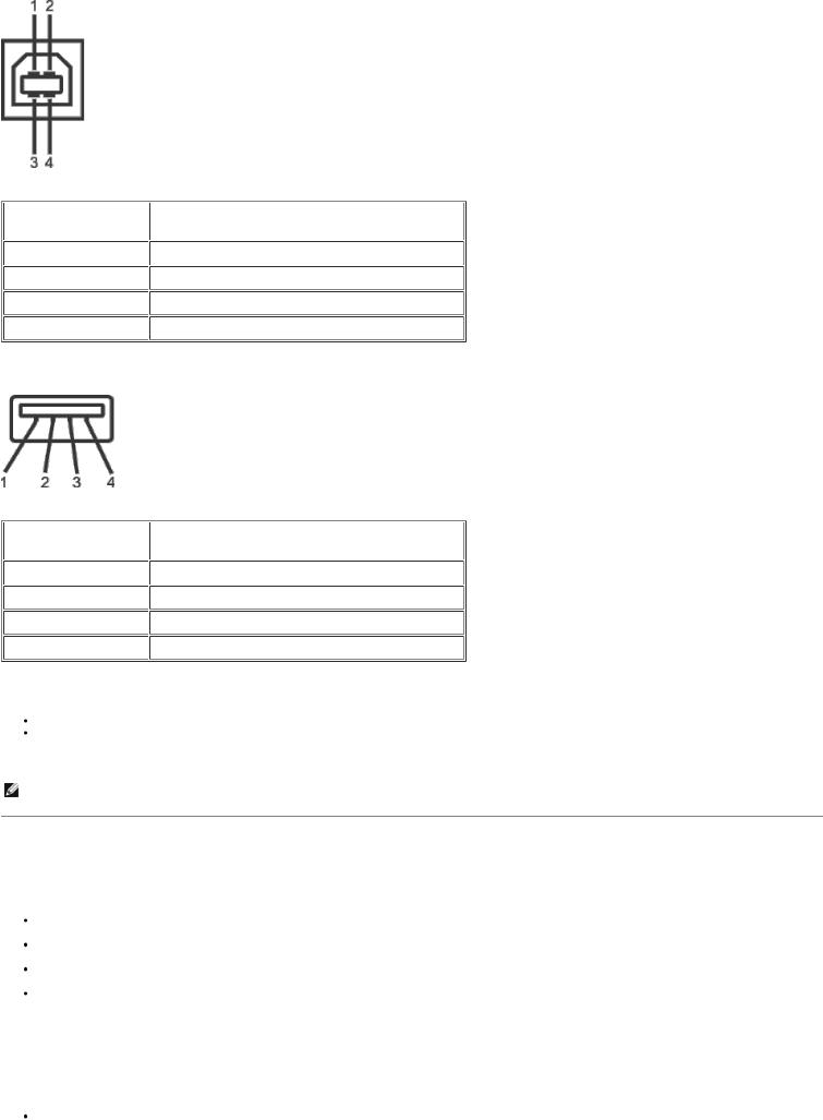
Pin Number |
4-pin Side of the connector |
1 |
DMU |
2 |
VCC |
3 |
DPU |
4 |
GND |
USB Downstream Connector
Pin Number |
4-Pin Side of the Signal Cable |
1 |
VCC |
2 |
DMD |
3 |
DPD |
4 |
GND |
USB Ports
1 upstream - rear
4 downstream - 2 on rear; 2 on right side
 NOTE: USB 2.0 capability requires 2.0-capable computer
NOTE: The monitor's USB interface works only when the monitor is on or in power save mode, If you switch the monitor off and then on, attached peripherals may take a few seconds to resume normal functionality.
Card Reader Specifications
Overview
The Flash Memory Card Reader is a USB storage device that allows users to read and write information from and into the memory card. The Flash Memory Card Reader is automatically recognized by Windows® 2000 and XP.
Once installed and recognized, each separate memory card (slot) appears as a separate drive/drive letter.
All standard file operations (copy, delete, drag-and-drop, etc.) can be performed with this drive.
Features
The Flash Memory Card Reader has the following features:
Supports Windows 2000 and XP operating systems
No Windows 9X support from Dell
Mass Storage Class device (No drivers are required under Windows 2000 and XP)
USB-IF certification
Supports various memory card media
Slot Number |
Flash memory cards type |
1 |
CompactFlash type I/II Card (CF I/II)/ MicroDrive (MD) |
2 |
SmartMedia Card (SMC) |
3 |
Memory Stick Card (MS) ./ Memory Stick Pro Card (MS PRO) / Memory Stick Duo (with Adapter) |
4 |
Secure Digital Card (SD)/ MultiMediaCard (MMC)/ Mini Secure Digital (with Adapter) |
General
Connection type |
USB 2.0 High Speed Device (USB Full Speed Device compatible) |
Supported OS |
Windows 2000 and XP |
Performance
Transfer Speed |
Read: 480 Mb/s (max.) |
|
Write: 480 Mb/s (max.) |
Dell™Sound Bar (Optional) Specifications
System Frequency Response |
95 Hz to 20 kHz @ 10 dB below avg. SPL |
Total Power Output |
14 W continuous average power (all speakers operating) @ 10% (THD+N), 1 kHz (FTC rated) |
Headphone Jack |
40 mW continuous average power (RL = 32Ω) @ 10% (THD+N), 1 kHz |
Output Power |
|
Input Sensitivity for |
500 ± 50 mVrms @ 1 kHz |
Rated Output |
|
Input Impedance |
>10kΩ |
Maximum Input Signal |
2 Vrms |
Voltage |
|
Controls |
Power On/Off Volume Control |
Input Cables |
3.0 m ± 0.1 m AWG26 black cable attached to enclosure, with 3.5 mm lime green stereo plug |
Power Requirements |
DC12V, 1.5A +/-10% |

Power Cord Length |
305 mm ± 15 mm AWG22 black cable attached to enclosure, with DC plug (5.5 x 2.1 x 12 mm) |
Operating Temperature Range |
10°C to 40°C |
Humidity, Non-condensing |
95% RH @ 40 °C |
Plug and Play Capability
You can install the monitor in any Plug and Play-compatible system. The monitor automatically provides the computer system with its Extended Display Identification Data (EDID) using Display Data Channel (DDC) protocols so the system can configure itself and optimize the monitor settings. If desired, the user can select different settings, but in most cases monitor installation is automatic.
Caring for Your Monitor
CAUTION: Read and follow the Safety Information before cleaning the monitor.
CAUTION: Before cleaning the monitor, unplug the monitor from the electrical outlet.
 To clean your antistatic screen, lightly dampen a soft, clean cloth with water. If possible, use a special screen-cleaning tissue or solution suitable for the antistatic coating. Do not use benzene, thinner, ammonia, abrasive cleaners, or compressed air.
 Use a lightly-dampened, warm cloth to clean the plastics. Avoid using detergent of any kind as some detergents leave a milky film on the plastics.
 If you notice a white powder when you unpack your monitor, wipe it off with a cloth. This white powder occurs during the shipping of the monitor.
  Handle your monitor with care as darker-colored plastics may scratch and show white scuff marks more than lighter-colored monitor.
Back to Contents Page

Back to Contents Page
Using Your Adjustable Monitor Stand
Dell™ 2405FPW Flat Panel Monitor
 Attaching the Stand
 Organizing Your Cables
 Using the Tilt, Swivel, Vertical Extension
 Removing the Stand
Attaching the Stand
1.Place the stand on a flat surface.
2.Fit the groove on the back of the monitor onto the three teeth of upper stand.
3.Lower the monitor so that the monitor mounting area snaps on/locks to stand.
Organizing Your Cables

After attaching all necessary cables to your monitor and computer, (See Connecting Your Monitor for cable attachment,) use the cable holder to neatly organize all cables as shown above.
Using the Tilt, Swivel and Vertical Extension
Tilt/Swivel
With the built-in pedestal, you can tilt and/or swivel the monitor for the most comfortable viewing angle.
NOTE: Stand is detached and extended when the monitor is shipped from the factory.
Vertical Extension
Stand extends vertically up to 100mm via the stand lock release button.

NOTE: If locked in the down position, press the stand lock release button on the bottom rear of stand. Lift the front panel up and extend the stand to the desired height.
NOTICE: Before relocating/moving the monitor to a different location, make sure that the stand is LOCKED DOWN. To lock it down, lower the height of the panel until it clicks and is locked into place.
Removing the Stand
After placing the monitor panel on a soft cloth or cushion, press and hold the LCD removal button, and then remove the
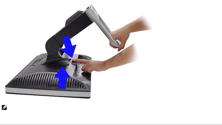
stand.
NOTE: To prevent scratches on the LCD screen while removing the stand, ensure that the monitor is placed on a clean surface.
Back to Contents Page

Back to Contents Page
Setting Up Your Monitor
Dell™ 2405FPW Flat Panel Monitor
 Connecting Your Monitor
 Using the Front Panel Buttons
 Using the OSD
 Using the Dell™ Sound Bar (Optional)
 Using the Card Reader
Connecting Your Monitor
CAUTION: Before you begin any of the procedures in this section, follow the Safety Information.
1Power cord connector
2DC power connector for Dell™ Sound Bar
3S-Video connector (cable not included)
4Composite video connector (cable not included)
5Component video (Y Pb Pr) connectors (cable not included)
6DVI connector
7VGA connector
8USB upstream port
9USB downstream ports
Turn off your computer and disconnect the power cable.
Connect either the white (digital DVI-D) or the blue (analog D-sub) display connector cable to the corresponding video port on the back of your computer. Do not use both cables on the same computer. The only case in which both cables can be used is if they are connected to two different computers with appropriate video systems. (Graphics are for illustration only. System appearance may vary).
Connect the upstream USB port (cable supplied) to an appropriate USB port on your computer .
Connect USB peripherals to the downstream USB ports (rear or side) on the monitor. (See rear or bottom view for details.)
 Connect the DC power cable for your monitor to the power port on the back of the monitor.
 Plug the power cables for your computer and monitor into a nearby outlet.
 Turn on the monitor and computer.
If your monitor displays an image, installation is complete. If it does not display an image, see Solving Problems.  Use the cable holder on the monitor stand to neatly organize the cables.
NOTE: If your computer does not support the DVI connector, you can leave the cable unconnected or remove it.
NOTE: For USB peripherals already connected to your computer, changing the USB connection to your monitor is not necessary.
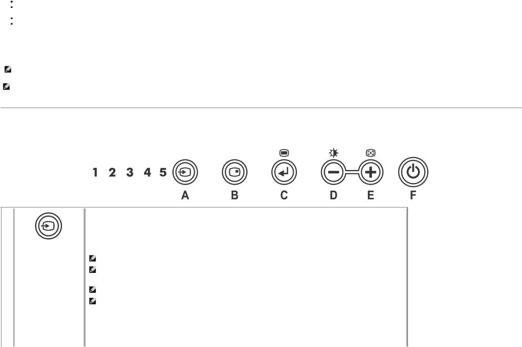
Using the Front Panel Buttons
Use the control buttons on the front of the monitor to adjust the characteristics of the image being displayed. As you use these buttons to adjust the controls, an OSD shows their numeric values as they change.
A |
Use Input Select button to select between five different video signals that may be connected to your monitor. |
|
|
1. |
VGA input |
|
2. |
DVI-D input |
|
3. |
S- Video input |
Input select |
4. |
Composite video input |
5. |
Component video (Y Pb Pr) input |
|
NOTE: VGA is referred to as D-SUB in the OSD
NOTE: The floating 'Dell™ - self-test Feature Check' dialog will also appear on-screen (against a black background) if the monitor cannot sense a video signal. Depending upon the selected input, one of the dialogs shown below will scroll continually.
NOTE: Self test feature check is not available for S-Video, Composite video and Component video (Y Pb Pr) modes.
NOTE: If VGA/DVI-D cable is unconnected, monitor automatically looks for VGA/DVI-D connection and indicates the "Self
Test Feature Check" pattern on the screen for the disconnected port that was last used.

or
|
If it finds a cable connection with the computer, then it looks for activated VGA/DVI-D port on the computer and makes the |
|
selection for that port. |
|
NOTE: If S-video/Composite video /Component video (Y Pb Pr) cable is not connected or the video source is turned off, the |
|
screen will be turned off, when any button except power button is pressed. The monitor displays "No Input Signal" for the |
|
corresponding connection . |
B |
Use this button to activate PIP (Picture-in-Picture)/PBP (Picture-by-Picture) mode adjustment. |
|
Pressing this button continually will cycle the sub-screen through the PIP -> PBP -> OFF (Original state without sub-screen) modes |
|
with the corresponding brief OSD menu. |
|
PIP/PBP Select |
|
PIP Settings: |
Pressing PIP/PBP  for the first time in sequence (PIP) will open "PIP Setting" Menu.
The details of the menu is as follows:
-PIP Source : To select an input signal for PIP. (VGA/DVI/S-video/Composite/Component) Use  and
and  to choose and
  to select.
-Swap : To switch the main-screen and sub-screen in PIP mode.
Use  and
and  to choose and
  to select.
-PIP size : To adjust the size of the PIP screen between "Small","Medium", and "Large". Use  and
and  to choose and
  to select.
-Position : Move the PIP window.
Use  and
and  to choose and
  to select.
- Advanced Menu : To adjust the detail menu of PIP Setting. See PIP/PBP Settings. Use  to select.
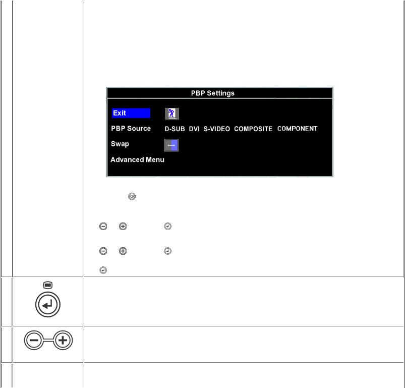
PBP Settings:
Pressing PIP/PBP |
for the second time in sequence(PIP->PBP) will open "PBP Settings" Menu. |
||
The details of the menu is as follows: |
|||
- PBP Source : To select an input signal for PBP. (VGA/DVI/Svideo/Composite/Component) |
|||
Use |
and |
to choose and |
to select. The PBP active sub-screen is shown with "blue border" beside the main-screen on |
the right hand side.
|
- Swap : To switch the main-screen and sub-screen in PBP mode. |
|||
|
Use |
and |
to choose and |
to select. |
|
- Advanced Menu : To adjust the detail menu of PIP Setting. See PIP/PBP Settings. |
|||
|
Use |
to select. |
|
|
C |
The MENU button is used to open the on-screen display(OSD) and select the OSD Menu. See Accessing the Menu System. |
|||
|
OSD menu & select |
D, |
Use these buttons for navigating and adjusting the slider-bar(decrease/increase ranges) controls in the OSD. |
E |
|
|
Minus (- ) and Plus (+) |
D |
Use this button to activate Brightness/Contrast adjustment. |
With the Menu off, push the  button to display the Brightness/Contrast adjustment menu.
Brightness / Contrast
E
Auto Adjust
F
Power Button &
Indicator
Adjust Brightness first, then adjust Contrast only if further adjustment is necessary.
1.Navigate to the Brightness control function
2.Select using  key.
key.
3.Push the  button to increase Brightness;
push the  button to decrease Brightness (min 0 ~ max 100).
The Contrast function adjusts the degree of difference between darkness and lightness on the monitor screen.
1.Navigate to the Contrast control function
2.Select using  key.
key.
3.Push the  button to increase the contrast;
push the  button to decrease the contrast (min 0 ~ max 100).
NOTE: When using '2: DVI-D Input', the contrast adjustment is not available.
Use this button to activate automatic setup and adjustment. The following dialog will appear on a black screen as the monitor selfadjusts to the current input:
Auto Adjust In Progress
Auto Adjustment  button allows the monitor to self-adjust to the incoming video signal. After using Auto Adjustment, you can further tune your monitor by using the Pixel Clock, Phase controls in the OSD.
NOTE: Auto Adjust does not occur if you press the button while there are no active video input signals, or attached cables.
The green LED indicates the monitor is on and fully functional. An amber LED indicates DPMS power save mode. The Power button turns the monitor on and off.
Using the OSD
Accessing the Menu System
1. With the menu off, push the MENU button to open the OSD system and display the main features menu.

AFunction icons
BMain Menu
CMenu icon
DMenu and Sub Menu name
ESelected Input
FCurrent resolution
GSelected PIP / PBP
2.Push the  and
and  buttons to move between the function icons. As you move from one icon to another, the function name is highlighted to reflect the function or group of functions (sub-menus) represented by that icon. See the table below for a complete list of all the functions available for the monitor.
3.Push the MENU button once to activate the highlighted function; Push  /
/  to select the desired parameter, push menu to enter the slidebar then use the
  and
and  buttons, according to the indicators on the menu, to make your changes.
Icon |
Menu Name and Sub- |
Description |
|
menus |
|
EXIT This is used to exit out of the Main menu.
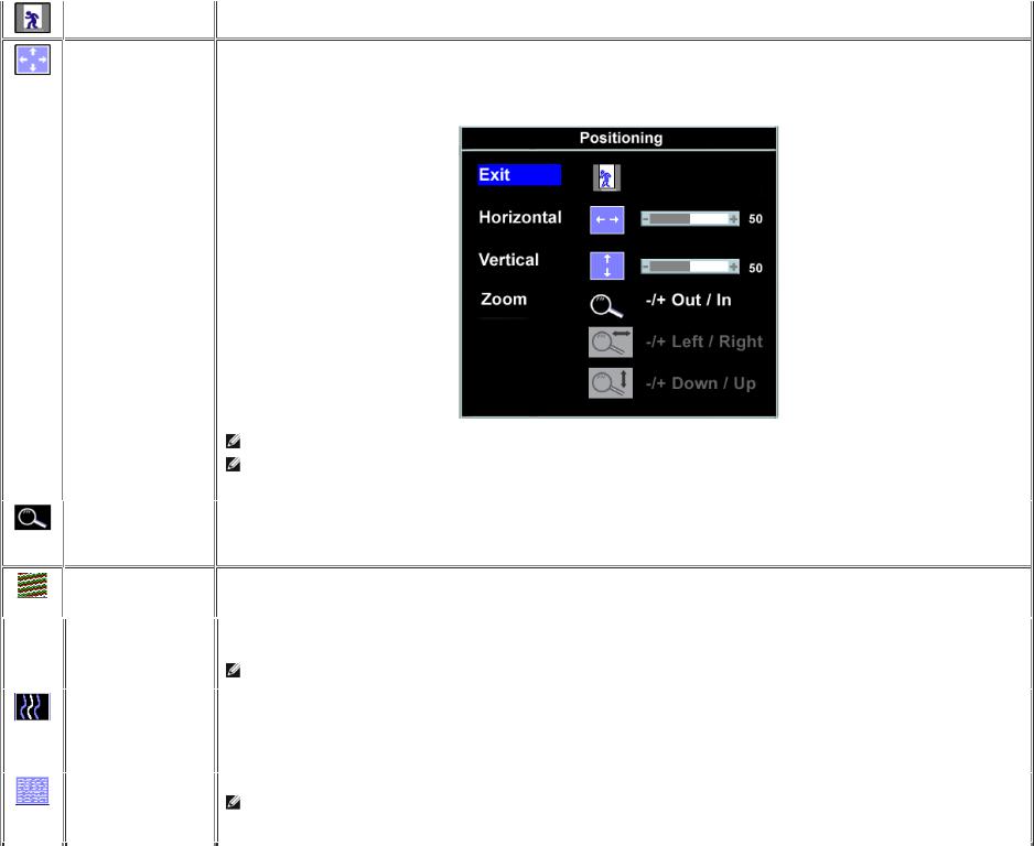
Positioning: Positioning moves the viewing area around on the monitor screen.
Horizontal When making changes to either the 'Horizontal' or 'Vertical' settings, no changes will occur to the size of the viewing area: the image will simply be shifted Vertical in response to your selection/change.
Minimum is '0' (-). Maximum is '100' (+).
NOTE: When using '2: DVI-D', '3: S-video Input', '4: Composite', '5: Component video (Y Pb Pr)' the positioning adjustments are not available.
NOTE: Horizontal and Vertical OSD positioning adjusts with respect to landscape (default) or portrait display rotation when used in conjunction with OSD rotation feature. See OSD Settings for details.
Zoom You can zoom out or in the image through the zoom function. If you want to focus on a small area of image, to zoom in the specific area will let you see the details easier. After activating the zoom in function, you can also move the zoom lens around through zoom left/right/up/down functions.
Using the and
and  keys.
keys.
Image settings:
Auto Adjust Even though your computer system can recognize your new flat panel monitor on startup, the 'Auto Adjustment' function will optimize the display settings for use with your particular setup.
NOTE: In most cases, 'Auto Adjust' will produce the best image for your configuration.
Pixel Clock The Phase and Pixel Clock adjustments allow you to more closely adjust your monitor to your preference. These settings are accessed through the main OSD menu, by selecting 'Image Settings'.
Use the  and
and  buttons to adjust away interference. Minimum: 0 ~ Maximum: 100
Phase If satisfactory results are not obtained using the Phase adjustment, use the Pixel Clock (course) adjustment and then use Phase (fine), again.
NOTE: Pixel Clock and Phase Adjustments are only available for "VGA" input.

Sharpness
Scaling
Video Mode
Color Settings:
This feature can make the image look sharper or softer. Use  or
or  to toggle between the 5 settings. Settings 1 to 5 will make the image look softer or sharper.
NOTE: Sharpness is only available for "S-video" and "Composite" modes. This function is not available in "VGA" or "DVI-D modes.
Scaling optimizes the display for the type of software you are using. Includes '1:1', 'fill' and 'aspect'.
a.1:1: Turns off Scaling feature and displays an image size based on the input resolution.
b.Fill: Image size up-scaled to fill the entire screen, image maybe distorted or elongated due to non-proportional scaling of height and width.
c.Aspect: Increases Vertical image size to fit screen and adjusts Horizontal size to maintain proportional image.
Use  and
and  to scroll through the 3 alternatives '1:1', 'fill' and 'aspect'.
NOTE: "Auto Adjust" will produce the best image for your configuration.
Turning video mode "On" reveals the true to reality crisp video images using S-video and Composite video inputs. You can choose between "On" and "Off".
On : Displays optimum video image by automatically enhancing colors in the brighter color patterns with brighter background video and darker color patterns in the darker backer background video. The setting is set to "On" by default.
Off : Displays the standard colors as relayed by the video source.
Color Settings adjusts the color temperature, color hue and saturation.
The color hue is most noticeable in areas of white.
Loading...