


 Loading...
Dell™ PowerEdge™ 1955 Systems
Hardware Owners Manual
w w w . d e l l . c o m | s u p p o r t . d e l l . c o m

Notes, Notices, and Cautions
NOTE: A NOTE indicates important information that helps you make better use of your computer.
NOTICE: A NOTICE indicates either potential damage to hardware or loss of data and tells you how to avoid the problem.
 CAUTION: A CAUTION indicates a potential for property damage, personal injury, or death.
____________________
Information in this document is subject to change without notice. © 2006 Dell Inc. All rights reserved.
Reproduction in any manner whatsoever without the written permission of Dell Inc. is strictly forbidden.
Trademarks used in this text: Dell, the DELL logo, Inspiron, Dell Precision, Dimension, OptiPlex, Latitude, PowerEdge, PowerVault, PowerApp, and Dell OpenManage are trademarks of Dell Inc.; Intel, Pentium, Xeon, and Celeron are registered trademarks of Intel Corporation; Microsoft and Windows are registered trademarks of Microsoft Corporation.
Other trademarks and trade names may be used in this document to refer to either the entities claiming the marks and names or their products. Dell Inc. disclaims any proprietary interest in trademarks and trade names other than its own.
January 2006

Contents
1 About Your System. . . . . . . . . . . . . . . . . . . . . . . . . . . . . |
9 |
Other Information You May Need . . . . . . . . . . . . . . . . . . . . . . . . . |
9 |
System Overview . . . . . . . . . . . . . . . . . . . . . . . . . . . . . . . . . |
10 |
System Status Features . . . . . . . . . . . . . . . . . . . . . . . . . . . . . |
10 |
Server Module Features . . . . . . . . . . . . . . . . . . . . . . . . . . . . . |
12 |
Using USB Diskette or USB CD Drives . . . . . . . . . . . . . . . . . . . |
16 |
Hard-Drive Features . . . . . . . . . . . . . . . . . . . . . . . . . . . . . . . |
16 |
Back-Panel Features. . . . . . . . . . . . . . . . . . . . . . . . . . . . . . . |
18 |
Power Supply Indicator. . . . . . . . . . . . . . . . . . . . . . . . . . . |
19 |
Fan Module Indicators . . . . . . . . . . . . . . . . . . . . . . . . . . . |
21 |
KVM Modules . . . . . . . . . . . . . . . . . . . . . . . . . . . . . . . . . . |
22 |
Avocent Analog KVM Switch Module . . . . . . . . . . . . . . . . . . . |
22 |
Avocent Digital Access KVM Switch Module . . . . . . . . . . . . . . . |
24 |
DRAC/MC Module . . . . . . . . . . . . . . . . . . . . . . . . . . . . . . . . |
26 |
Important I/O Configuration Considerations . . . . . . . . . . . . . . . . |
27 |
DRAC/MC Firmware Requirements . . . . . . . . . . . . . . . . . . . . . |
28 |
I/O Connectivity . . . . . . . . . . . . . . . . . . . . . . . . . . . . . . . . . |
28 |
Guidelines for Installing Connectivity Modules . . . . . . . . . . . . . . |
28 |
PowerConnect 5316M Ethernet Switch Module . . . . . . . . . . . . . . |
29 |
Fibre Channel Pass-Through Module. . . . . . . . . . . . . . . . . . . . |
31 |
Fibre Channel Switch Module . . . . . . . . . . . . . . . . . . . . . . . |
32 |
Infiniband Pass-through Module . . . . . . . . . . . . . . . . . . . . . . |
32 |
Gb Ethernet Pass-through Module . . . . . . . . . . . . . . . . . . . . . |
33 |
Server Module Messages . . . . . . . . . . . . . . . . . . . . . . . . . . . . |
34 |
Warning Messages . . . . . . . . . . . . . . . . . . . . . . . . . . . . . . . |
40 |
Diagnostics Messages. . . . . . . . . . . . . . . . . . . . . . . . . . . . . . |
40 |
Alert Messages . . . . . . . . . . . . . . . . . . . . . . . . . . . . . . . . . |
41 |
Contents 3

2 Using the System Setup Program . . . . . . . . . . . . . . . . . . |
43 |
Entering the System Setup Program . . . . . . . . . . . . . . . . . . . . . . . |
43 |
Responding to Error Messages. . . . . . . . . . . . . . . . . . . . . . . |
43 |
Using the System Setup Program. . . . . . . . . . . . . . . . . . . . . . |
44 |
System Setup Options . . . . . . . . . . . . . . . . . . . . . . . . . . . . . . |
44 |
Main Screen . . . . . . . . . . . . . . . . . . . . . . . . . . . . . . . . |
44 |
Memory Information Screen . . . . . . . . . . . . . . . . . . . . . . . . |
47 |
CPU Information Screen . . . . . . . . . . . . . . . . . . . . . . . . . . |
47 |
Integrated Devices Screen . . . . . . . . . . . . . . . . . . . . . . . . . |
48 |
Serial Communication Screen . . . . . . . . . . . . . . . . . . . . . . . |
49 |
System Security Screen . . . . . . . . . . . . . . . . . . . . . . . . . . |
49 |
Exit Screen . . . . . . . . . . . . . . . . . . . . . . . . . . . . . . . . . |
50 |
System and Setup Password Features. . . . . . . . . . . . . . . . . . . . . . |
51 |
Using the System Password . . . . . . . . . . . . . . . . . . . . . . . . |
51 |
Using the Setup Password . . . . . . . . . . . . . . . . . . . . . . . . . |
53 |
Disabling a Forgotten Password. . . . . . . . . . . . . . . . . . . . . . . . . |
54 |
Acquiring the asset.com Utility . . . . . . . . . . . . . . . . . . . . . . . . . |
54 |
Baseboard Management Controller Configuration . . . . . . . . . . . . . . . |
54 |
Entering the BMC Setup Module . . . . . . . . . . . . . . . . . . . . . . |
55 |
BMC Setup Module Options . . . . . . . . . . . . . . . . . . . . . . . . |
55 |
3 Installing System Options . . . . . . . . . . . . . . . . . . . . . . . . |
57 |
Power Supply Modules . . . . . . . . . . . . . . . . . . . . . . . . . . . . . |
58 |
System Power Guidelines. . . . . . . . . . . . . . . . . . . . . . . . . . |
58 |
Removing a Power Supply Module . . . . . . . . . . . . . . . . . . . . . |
58 |
Installing a Power Supply Module . . . . . . . . . . . . . . . . . . . . . |
59 |
Fan Modules . . . . . . . . . . . . . . . . . . . . . . . . . . . . . . . . . . . |
59 |
Removing a Fan . . . . . . . . . . . . . . . . . . . . . . . . . . . . . . . |
60 |
Installing a Fan . . . . . . . . . . . . . . . . . . . . . . . . . . . . . . . |
61 |
DRAC/MC Module . . . . . . . . . . . . . . . . . . . . . . . . . . . . . . . . |
61 |
Removing a DRAC/MC Module . . . . . . . . . . . . . . . . . . . . . . . |
61 |
Installing a DRAC/MC Module . . . . . . . . . . . . . . . . . . . . . . . |
62 |
Important I/O Configuration Considerations . . . . . . . . . . . . . . . . |
62 |
DRAC/MC Firmware Requirements . . . . . . . . . . . . . . . . . . . . . |
63 |
4 Contents

KVM Module . . . . . . . . . . . . . . . . . . . . . . . . . . . . . . . . . . . |
63 |
Removing a KVM Module . . . . . . . . . . . . . . . . . . . . . . . . . . |
63 |
Installing a KVM Module . . . . . . . . . . . . . . . . . . . . . . . . . . |
63 |
Tiering an Avocent Analog KVM Switch or Avocent Digital |
|
Access KVM Switch From a Analog KVM Switch . . . . . . . . . . . . . |
65 |
Tiering an Avocent Analog KVM Switch From a Dell Console Switch . . . |
68 |
Tiering an Avocent Digital Access KVM Switch From a Dell |
|
Console Switch . . . . . . . . . . . . . . . . . . . . . . . . . . . . . . . |
69 |
Chassis I/O Module . . . . . . . . . . . . . . . . . . . . . . . . . . . . . . . |
70 |
I/O Module Placements. . . . . . . . . . . . . . . . . . . . . . . . . . . |
71 |
Installing an I/O Module . . . . . . . . . . . . . . . . . . . . . . . . . . |
72 |
Server Modules . . . . . . . . . . . . . . . . . . . . . . . . . . . . . . . . . |
73 |
Removing a Server Module . . . . . . . . . . . . . . . . . . . . . . . . . |
73 |
Installing a Server Module . . . . . . . . . . . . . . . . . . . . . . . . . |
74 |
Opening the Server Module . . . . . . . . . . . . . . . . . . . . . . . . |
75 |
Closing the Server Module . . . . . . . . . . . . . . . . . . . . . . . . . |
76 |
Removing and Installing Server Module Components . . . . . . . . . . . . . |
77 |
Memory . . . . . . . . . . . . . . . . . . . . . . . . . . . . . . . . . . . |
77 |
General Memory Module Installation Guidelines . . . . . . . . . . . . . |
78 |
Memory Sparing . . . . . . . . . . . . . . . . . . . . . . . . . . . . . . |
78 |
Memory Mirroring . . . . . . . . . . . . . . . . . . . . . . . . . . . . . |
79 |
Sample Memory Configurations . . . . . . . . . . . . . . . . . . . . . . |
80 |
I/O Module Daughter Card . . . . . . . . . . . . . . . . . . . . . . . . . |
82 |
Activating the Integrated NIC TOE . . . . . . . . . . . . . . . . . . . . . |
84 |
Processors . . . . . . . . . . . . . . . . . . . . . . . . . . . . . . . . . |
84 |
Server Module Battery . . . . . . . . . . . . . . . . . . . . . . . . . . . |
88 |
Hard Drives . . . . . . . . . . . . . . . . . . . . . . . . . . . . . . . . . |
89 |
Removing a Hard Drive . . . . . . . . . . . . . . . . . . . . . . . . . . . |
90 |
Configuring the Boot Drive . . . . . . . . . . . . . . . . . . . . . . . . . |
91 |
Removing a Hard Drive From a Hard-Drive Carrier. . . . . . . . . . . . . |
91 |
Installing a Hard Drive Into a Drive Carrier . . . . . . . . . . . . . . . . . |
91 |
Back-Panel Module Cage Assembly (Service-Only Procedure) . . . . . . . . |
92 |
Removing the Back-Panel Module Cage Assembly . . . . . . . . . . . . |
92 |
Installing the Back-Panel Module Cage Assembly. . . . . . . . . . . . . |
93 |
Chassis Control Panel Assembly (Service-Only Procedure) . . . . . . . . . . |
94 |
Removing the Chassis Control Panel . . . . . . . . . . . . . . . . . . . . |
94 |
Installing the Chassis Control Panel . . . . . . . . . . . . . . . . . . . . |
95 |
Contents 5

Server Module Control Panel Assembly (Service-Only Procedure) . . . . . . |
96 |
Removing the Server Module Control Panel . . . . . . . . . . . . . . . . |
96 |
Installing the Server Module Control Panel . . . . . . . . . . . . . . . . |
97 |
System Board (Service-Only Procedure) . . . . . . . . . . . . . . . . . . . . |
98 |
Removing the System Board . . . . . . . . . . . . . . . . . . . . . . . . |
98 |
Installing the System Board. . . . . . . . . . . . . . . . . . . . . . . . . |
99 |
4 Troubleshooting Your System . . . . . . . . . . . . . . . . . . . . |
101 |
Safety First—For You and Your System . . . . . . . . . . . . . . . . . . . . |
101 |
Start-Up Routine . . . . . . . . . . . . . . . . . . . . . . . . . . . . . . . . |
101 |
Checking the Equipment . . . . . . . . . . . . . . . . . . . . . . . . . . . . |
101 |
Troubleshooting External Connections . . . . . . . . . . . . . . . . . . . . |
102 |
Troubleshooting the Video Subsystem . . . . . . . . . . . . . . . . . . |
102 |
Troubleshooting the Keyboard . . . . . . . . . . . . . . . . . . . . . . |
103 |
Troubleshooting the Mouse. . . . . . . . . . . . . . . . . . . . . . . . |
104 |
Troubleshooting USB Devices . . . . . . . . . . . . . . . . . . . . . . |
105 |
Responding to a Systems Management Alert Message. . . . . . . . . . . . |
105 |
Troubleshooting a Wet System. . . . . . . . . . . . . . . . . . . . . . . . . |
106 |
Troubleshooting a Damaged System. . . . . . . . . . . . . . . . . . . . . . |
107 |
Troubleshooting System Components . . . . . . . . . . . . . . . . . . . . . |
107 |
Troubleshooting Power Supply Modules . . . . . . . . . . . . . . . . . |
107 |
Troubleshooting Fan Modules . . . . . . . . . . . . . . . . . . . . . . |
108 |
Troubleshooting the DRAC/MC Module . . . . . . . . . . . . . . . . . |
109 |
Troubleshooting a Network Switch Module . . . . . . . . . . . . . . . |
110 |
Troubleshooting Server Module Components . . . . . . . . . . . . . . . . . |
110 |
Inside the Server Module . . . . . . . . . . . . . . . . . . . . . . . . . |
111 |
Troubleshooting Server Module Memory . . . . . . . . . . . . . . . . |
112 |
Troubleshooting Hard Drives . . . . . . . . . . . . . . . . . . . . . . . |
113 |
Troubleshooting Microprocessors . . . . . . . . . . . . . . . . . . . . |
114 |
Troubleshooting the Server Module Board. . . . . . . . . . . . . . . . |
114 |
Troubleshooting the Server Module Battery . . . . . . . . . . . . . . . |
115 |
6 Contents

5 Running System Diagnostics. . . . . . . . . . . . . . . . . . . . . |
117 |
Using Server Administrator Diagnostics . . . . . . . . . . . . . . . . . . . |
117 |
System Diagnostics Features . . . . . . . . . . . . . . . . . . . . . . . . . |
117 |
When to Use the System Diagnostics . . . . . . . . . . . . . . . . . . . . . |
118 |
Running the System Diagnostics . . . . . . . . . . . . . . . . . . . . . . . |
118 |
From the Utility Partition . . . . . . . . . . . . . . . . . . . . . . . . . |
118 |
From a USB Flash Drive. . . . . . . . . . . . . . . . . . . . . . . . . . |
118 |
System Diagnostics Testing Options. . . . . . . . . . . . . . . . . . . . . . |
119 |
Using the Advanced Testing Options . . . . . . . . . . . . . . . . . . . . . |
119 |
Error Messages . . . . . . . . . . . . . . . . . . . . . . . . . . . . . . . . |
120 |
6 DIP Switch Settings and Connectors . . . . . . . . . . . . . . . |
121 |
DIP Switch Settings—A General Explanation . . . . . . . . . . . . . . . . |
121 |
DIP Switches . . . . . . . . . . . . . . . . . . . . . . . . . . . . . . . |
121 |
Server Module Board DIP Switch . . . . . . . . . . . . . . . . . . . . . . . |
122 |
Server Module Board Connectors . . . . . . . . . . . . . . . . . . . . . . . |
123 |
Disabling a Forgotten Password. . . . . . . . . . . . . . . . . . . . . . . . |
126 |
7 |
Getting Help . . . . . . . . . . . . . . . . . . . . . . . . . . . . . . . . |
127 |
|
Technical Assistance . . . . . . . . . . . . . . . . . . . . . . . . . . . . . |
127 |
|
Online Services . . . . . . . . . . . . . . . . . . . . . . . . . . . . . . |
127 |
|
AutoTech Service . . . . . . . . . . . . . . . . . . . . . . . . . . . . . |
128 |
|
Automated Order-Status Service . . . . . . . . . . . . . . . . . . . . . |
128 |
|
Technical Support Service . . . . . . . . . . . . . . . . . . . . . . . . |
128 |
|
Dell Enterprise Training and Certification. . . . . . . . . . . . . . . . . . . |
129 |
|
Problems With Your Order . . . . . . . . . . . . . . . . . . . . . . . . . . . |
129 |
|
Product Information . . . . . . . . . . . . . . . . . . . . . . . . . . . . . . |
129 |
|
Returning Items for Warranty Repair or Credit . . . . . . . . . . . . . . . . |
129 |
Contents 7

Before You Call. . . . . . . . . . . . . . . . . . . . . . . . . . . . . . . . . |
129 |
Contacting Dell. . . . . . . . . . . . . . . . . . . . . . . . . . . . . . . . . |
132 |
Glossary . . . . . . . . . . . . . . . . . . . . . . . . . . . . . . . . . . . . . |
149 |
Index . . . . . . . . . . . . . . . . . . . . . . . . . . . . . . . . . . . . . . . . |
157 |
8 Contents

About Your System
Other Information You May Need
CAUTION: The Product Information Guide provides important safety and regulatory information. Warranty information may be included within this document or as a separate document.
•The Rack Installation Guide or Rack Installation Instructions included with your rack solution describes how to install your system into a rack.
•The Getting Started Guide provides an overview of system features, setting up your system, and technical specifications.
•The Configuration Guide provides information on initial configuration of the server modules and other modular components in your system.
•The Dell OpenManage Baseboard Management Controller User’s Guide provides detailed information on using the Baseboard Management Controller (BMC).
•The Dell Remote Access Controller/Modular Chassis User’s Guide provides detailed information on using the remote management features of the system.
•CDs included with your system provide documentation and tools for configuring and managing your system.
•Systems management software documentation describes the features, requirements, installation, and basic operation of the software.
•Operating system documentation describes how to install (if necessary), configure, and use the operating system software.
•Documentation for any components you purchased separately provides information to configure and install these options.
•Updates are sometimes included with the system to describe changes to the system, software, and/or documentation.
NOTE: Always check for updates on support.dell.com and read the updates first because they often supersede information in other documents.
•Release notes or readme files may be included to provide last-minute updates to the system or documentation or advanced technical reference material intended for experienced users or technicians.
About Your System |
9 |

System Overview
Your system can include up to ten server modules (or blades) (see Figure 1-1). Each server module functions as an individual server encompassing up to two microprocessors, up to two hot-pluggable hard drives, and up to eight memory modules. To function as a system, a server module is inserted into a chassis that supports power supplies, fan modules, a management module (Dell™ Remote Access Controller/Modular Chassis [DRAC/MC]), a KVM switch module, and at least one I/O module for network connectivity. The power supplies, fans, DRAC/MC, and I/O modules are shared resources of the server modules in the chassis. In addition, your system may also ship with an optional external USB diskette drive and an optional external USB CD drive, which you can use to set up and configure the server modules.
NOTE: To ensure proper operation and cooling, all bays must be populated at all times with either a server module or with a blank.
Figure 1-1. Server Modules
1 |
2 |
3 |
4 |
5 |
6 |
7 |
8 |
9 |
10 |
|
|
|
|
|
|
|
|
|
|
|
|
|
|
|
|
|
|
|
|
|
|
|
|
|
|
|
|
|
|
|
|
|
|
|
|
|
|
|
|
|
|
|
|
|
|
|
|
|
|
|
|
|
|
|
|
|
|
|
|
|
|
|
|
|
|
|
|
|
|
|
|
|
|
|
|
|
|
|
|
|
|
|
|
|
|
|
|
|
This section describes the major hardware and software features of your system and provides information about the indicators on the system's front and back panels. It also provides information about other documents you may need when setting up your system and how to obtain technical assistance.
System Status Features
The chassis has front-panel control features including power and identification buttons and indicators (see Figure 1-2). Press the power button to turn on the system; press and hold the power button to turn off the system. Pressing the identification button activates the identification indicator on both the front and back (on the KVM module) of the system. Table 1-1 shows the status features.
10 About Your System
Figure 1-2. Front-Panel Control and Indicators
 1
1
 2
2
 3
3
 4
4
|
|
|
|
|
|
|
|
|
|
|
|
|
|
|
|
|
|
|
|
|
|
|
|
|
|
|
|
|
|
|
|
|
|
1 |
system power indicator |
2 |
system power button |
3 |
identification indicator |
|||||||||||
4 |
identification button |
|
|
|
|
|
|
|
|
|
|
|
||||
Table 1-1. System Status Features |
|
|
|
|
|
|
|
|
||||||||
|
|
|
|
|
|
|
|
|
|
|
|
|
|
|
|
|
Indicator Type |
Icon |
Indicator |
Indicator Code |
|
|
|||||||||||
|
|
|
|
|
|
|
|
|
|
|
|
|
|
|
||
System power |
N/A |
None |
Turns the system on and off. Press to turn on the system. |
|||||||||||||
button |
|
|
|
|
|
|
|
|
Press and hold 10 seconds to turn off the system. |
|||||||
|
|
|
|
|
|
|
|
|
NOTE: The system power button controls power to all of the |
|||||||
|
|
|
|
|
|
|
|
|
server modules and I/O modules in the chassis. |
|||||||
|
|
|
|
|
|
|
|
|
|
|
|
|
|
|
|
|
System power |
|
|
|
Off |
System does not have power. |
|
|
|||||||||
indicator |
|
|
|
Green |
System power is on. |
|
|
|||||||||
|
|
|
|
|
|
|
|
|||||||||
|
|
|
|
|
|
Amber |
System is plugged in but is not turned on. |
|||||||||
|
|
|
|
|
|
|
|
|
|
|
|
|
|
|
||
Identification |
N/A |
None |
Turns on the identification indicators on both the front and |
|||||||||||||
button |
|
|
|
|
|
|
|
|
back (on the KVM switch module) of the chassis. |
|||||||
About Your System |
|
11 |
|

Table 1-1. System Status Features (continued)
Indicator Type |
Icon |
Indicator |
Indicator Code |
|
|
|
|
Identification |
|
Off |
Chassis is not being identified. This is the default. |
|
|||
indicator |
|
Amber, slow |
Chassis is being identified. Either the front or back |
|
|
||
|
|
blinking |
identification button has been pressed. This indicator can |
|
|
|
be turned off by pressing the identification button. |
|
|
Amber, fast |
System error. Will stop blinking when the error is resolved. |
|
|
blinking |
|
|
|
|
|
Server Module Features
Each server module has one power button and one KVM module selection button on the front (see Figure 1-3). The indicators include a power indicator, network link indicators, and a KVM module indicator. The server module also has a custom port on the front of the module. Use the custom cable included with your system to connect this port to two USB devices (for example, USB diskette drive, USB CD drive, USB mouse) and to video.
NOTE: The USB devices can only be connected by using the custom cable supplied with the system.
12 About Your System

Figure 1-3. Server Module Indicators
1
2
3
4
5
6
7
1 |
server module power indicator |
2 |
server module power button |
3 |
KVM selection indicator |
4 |
KVM selection button |
5 |
daughter card status indicator |
6 |
Ethernet network indicator |
7custom port (with custom cable - USB [2] and video)
About Your System |
|
13 |
|

Table 1-2 provides information about the status indicators.
Table 1-2. Server Module Features and Indicators
Indicator |
Icon |
Activity Indicator |
Indicator Code |
|
|
|
|
Server module |
|
Off |
Power is not available to the server module, the server |
power indicator |
|
|
module is not turned on, or the server module is installed |
|
|
|
incorrectly. For detailed information on installing a server |
|
|
|
module, see "Server Modules" on page 73. |
|
|
Green |
The module is turned on. |
|
|
Green blinking fast |
The module power is on and there is a fault with the server |
|
|
|
module. |
|
|
Green blinking slowly |
The module power is on and the server module is being |
|
|
|
remotely identified via the DRAC/MC. |
|
|
Amber |
The module power is off, but the system power is on. |
|
|
Amber blinking slowly |
The module power is off and the server module is being |
|
|
|
remotely identified via the DRAC/MC. |
|
|
Amber blinking fast |
The module power is off and there is a fault with the server |
|
|
|
module. |
|
|
|
|
Server module |
N/A |
None |
Turns server module power off and on. |
power button |
|
|
• If you turn off the module using the power button and |
|
|
|
the module is running an ACPI-compliant operating |
|
|
|
system, the module can perform an orderly shutdown |
|
|
|
before the power is turned off. |
|
|
|
• If the module is not running an ACPI-compliant |
|
|
|
operating system, power is turned off immediately after |
|
|
|
the power button is pressed. |
|
|
|
• Press and hold the button to turn off the server module |
|
|
|
immediately. |
|
|
|
The button is enabled in the System Setup program. When |
|
|
|
disabled, you can only use the button to turn on the server |
|
|
|
module. |
14 About Your System

Table 1-2. Server Module Features and Indicators (continued)
Indicator |
Icon |
Activity Indicator |
Indicator Code |
|
|
|
|
KVM selection |
|
Off |
The server module is not selected by the KVM. |
indicator |
|
|
|
|
|
Green |
The server module is selected for the KVM. |
|
|
Amber blinking |
The server module is not selected by the KVM and a power |
|
|
|
fault exists. |
|
|
Green/amber blinking |
The server module is selected for the KVM and a power fault |
|
|
|
exists. |
|
|
|
|
KVM selection |
N/A |
None |
Selects the server module for use with the KVM located on |
button |
|
|
the back of the system. See "Avocent Analog KVM Switch |
|
|
|
Module" on page 22 for information on selecting a server |
|
|
|
module by using the keyboard. |
|
|
|
|
Daughter card |
I/O |
Off |
Daughter card is not installed. |
status indicator |
|
Green |
Infiniband daughter card is installed, but no traffic is |
(Infiniband card |
|
||
|
|
detected. |
|
installed) |
|
|
|
|
|
|
|
|
|
Green blinking |
Infiniband daughter card is present and data transfers are |
|
|
|
occurring. |
|
|
|
|
Daughter card |
I/O |
Off |
Daughter card is not installed. |
status indicator |
|
Green |
A link exists. |
(Fibre channel |
|
||
|
|
|
|
daughter card |
|
Green blinking |
Fibre channel daughter-card data transfers are occurring. |
installed) |
|
|
|
|
|
|
|
Daughter card |
I/O |
Off |
Daughter card is not installed. |
status indicator |
|
Green |
A link exists. |
(Gb Ethernet |
|
||
|
|
|
|
daughter card |
|
Green blinking |
Gb Ethernet daughter-card data transfers are occurring. |
installed) |
|
|
|
|
|
|
|
Daughter card |
I/O |
Off |
Daughter card is not installed. |
status indicator |
|
Green |
A link exists. |
(TOE NIC |
|
||
|
|
|
|
daughter card |
|
Green blinking |
TOE NIC daughter card is installed and data transfers are |
installed) |
|
|
occurring. |
About Your System |
|
15 |
|

Table 1-2. Server Module Features and Indicators (continued)
Indicator |
Icon |
Activity Indicator |
Indicator Code |
|
|
|
|
Network indicators |
|
Off |
Indicates that the server module does not have a link to the |
|
|
|
Ethernet switch or pass-through module. |
|
|
Green on |
Indicates that the server module has a valid link to the |
|
|
|
network switch module. |
|
|
Green blinking |
Indicates network activity between the server module and |
|
|
|
the network switch module. |
|
|
|
NOTE: External network activity is not reported by this |
|
|
|
indicator. |
|
|
|
NOTE: This network indicator may also blink green due to |
|
|
|
systems management activity if you use the integrated NIC to |
|
|
|
remotely access your system’s Baseboard Management |
|
|
|
Controller (BMC). See "Baseboard Management Controller |
|
|
|
Configuration" on page 54. |
|
|
|
|
USB/video |
|
None |
Use the custom cable to connect external USB devices and |
connector |
|
|
video to the server module. |
Using USB Diskette or USB CD Drives
Each server module has a USB port on the front of the server module which allows you to connect a custom cable for a diskette drive or USB CD drive. The USB drives are used to configure the server module.
NOTICE: The system supports only Dell-branded USB 1.1 or USB 2.0 drives. The drive must be horizontal and level to operate properly.
NOTE: If the drive must be designated as the boot drive, connect the USB drive, restart the system, then enter the System Setup Program and set the drive as first in the boot sequence (see "Using the System Setup Program" on page 43). The USB device will be displayed in the boot order setup screen only if it is attached to the system before you run the System Setup program.
Hard-Drive Features
Each server module supports one or two hot-pluggable SAS hard drives, or one or two hot-pluggable SATA hard drives. See Figure 1-4 and Table 1-3 for information on the hard-drive indicators. Different patterns are displayed as drive events occur in the system.
NOTICE: Each server module must have a hard drive or a hard-drive blank installed in each hard-drive bay.
NOTICE: You cannot install a SAS drive and a SATA drive within a given server module (blade). However, you can install server modules (blades) with SAS drives and server modules with SATA drives in the same server enclosure.
16 About Your System

Figure 1-4. Hard-Drive Features and Indicators
 1
1


 2
2
1 |
drive activity indicator |
2 |
drive status indicator |
NOTE: The hard-drive status indicator is only functional for RAID hard drive configurations. For non-RAID configurations, only the drive-activity indicator is active.
Table 1-3. Hard-Drive Status Indicator Patterns (RAID Configurations Only)
Status Indicator State |
Indicator Code |
|
|
Off |
• Drive is ready for removal. |
|
• Drive bay is empty. |
|
• Power is off to the server module. |
Green |
Drive is online. |
Green, blinking slowly |
Drive is rebuilding. |
Green, blinking quickly |
Drive is being identified. |
Amber |
Drive has failed or has an error. See "Troubleshooting Hard |
|
Drives" on page 113. |
Amber blinking slowly, |
The drive has reported a predictive failure event, and should |
green blinking slowly, then off |
be replaced. |
|
|
About Your System |
|
17 |
|

Back-Panel Features
The back of the chassis supports four I/O module bays, the DRAC/MC, fan modules, and power supply modules. Figure 1-5 shows a sample configuration and the numbering for the bays. Table 1-4 provides information about the back-panel features.
Figure 1-5. Back-Panel Features
1 |
2 |
3 |
|
||
|
|
|
12 |
|
4 |
|
|
11 |
5 |
|
|
|
6 |
4 |
3 |
10

 7
7
|
2 |
|
|
|
1 |
8 |
|
|
|
|
|
|
|
|
9 |
|
|
|
|
|
1 |
I/O bay 2 |
2 |
fan modules (2) |
3 |
|
PowerConnect 5316M |
|
|
|
|
|
|
Ethernet switch module |
4 |
I/O bay 1 |
5 |
Fibre Channel pass-through |
6 |
|
I/O bay 3 |
|
|
|
module |
|
|
|
7 |
KVM module |
8 |
DRAC/MC module |
9 |
|
power supply modules (4) |
10 |
blanks (2) |
11 |
I/O bay 4 |
12 |
|
blanks (2) |
18 About Your System

Table 1-4. Back-Panel Features and Indicators
Component |
Indicator Description |
|
|
Power supply modules |
Provide information about power status (see "Power Supply Indicator Codes" on |
|
page 20). |
Fan modules |
Provide information about status of the system fans (see "Fan Module Indicators" |
|
on page 21). |
KVM module |
Provides information about the KVM module (see "KVM Modules" on page 22). |
DRAC/MC module |
Provides information about system status, system management status, and port |
|
status (see "DRAC/MC Module" on page 26). |
PowerConnect™ 5316M |
Provides information about the 10/100/1000 BASE-T network status (see |
Ethernet switch module |
"PowerConnect 5316M Ethernet Switch Module" on page 29). |
Fibre Channel pass-through |
Provides information about the Fibre Channel network status (see "Fibre |
module |
Channel Pass-Through Module" on page 31). |
Fibre Channel switch module |
Provides information about the Fibre Channel network status (see "Fibre |
|
Channel Switch Module" on page 32). |
Infiniband pass-through |
Provides information about the Infiniband network status (see "Infiniband Pass- |
module |
through Module" on page 32). |
Gb pass-through module |
Provides information about the network status (see "Gb Ethernet Pass-through |
|
Module" on page 33). |
|
|
Power Supply Indicator
Each hot-pluggable power supply has indicators that provide information about power status, fault, and the presence of AC power (see Figure 1-6). Table 1-5 lists the power supply indicator codes.
NOTE: Only 2100-W power supply modules are supported on your system. The 2100-W power supply modules require 180–240 V input from a PDU capable of providing AC current up to 29.2 A at 180 V input. If the power supply modules are plugged into 110-V electrical outlets, the system will not power up.
About Your System |
|
19 |
|
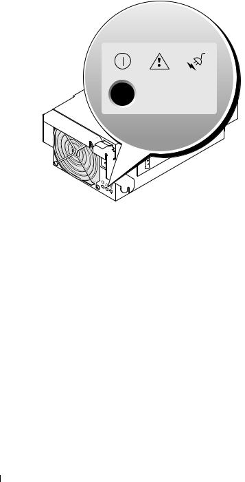
Figure 1-6. Power Supply Indicators
 1
1
3 
 2
2
1 fault indicator |
|
|
2 |
AC power present indicator |
3 |
DC power indicator |
Table 1-5. Power Supply Indicator Codes |
|
|
|
|||
|
|
|
|
|
|
|
Indicator |
Icon |
Activity |
Indicator Code |
|
|
|
|
|
|
Indicator |
|
|
|
|
|
|
|
|
|
|
DC power indicator |
|
|
Green |
The power supply is operational. |
|
|
|
|
|
||||
Fault indicator |
|
|
Amber |
The power supply is in a fault condition. The fault |
||
|
|
|
|
condition can result from either a failed power supply |
||
|
|
|
|
or a failed fan within the power supply. See "Power |
||
|
|
|
|
Supply Modules" on page 58. |
|
|
AC power present |
|
|
Green |
AC power is present at the power supply and the system |
||
indicator |
|
|
|
is connected to an AC power source. |
||
|
|
|
|
|
|
|
20 About Your System
Fan Module Indicators
Each hot-pluggable fan module contains two redundant fans (see Figure 1-7). Table 1-6 lists the fan indicator codes.
Figure 1-7. Fan Module Indicators
2
1
3
4
1 fan 1 fault indicator |
2 |
fan 1 present indicator |
3 |
fan 2 present indicator |
|
4 fan 2 fault indicator |
|
|
|
|
|
Table 1-6. Fan Module Indicator Codes |
|
|
|
|
|
|
|
|
|
|
|
Indicator |
Activity Indicator |
Indicator Code |
|
|
|
|
|
|
|
|
|
Fan 1 present indicator |
Off |
Fan 1 is not installed. |
|
|
|
|
Green |
Fan 1 is installed. |
|
|
|
Fan 1 fault indicator |
Off |
Fan 1 is operating normally. |
|
|
|
|
Amber |
Fan 1 has failed. See "Fan Modules" on page 59. |
|||
Fan 2 present indicator |
Off |
Fan 2 is not installed. |
|
|
|
|
Green |
Fan 2 is installed. |
|
|
|
About Your System |
|
21 |
|

Table 1-6. Fan Module Indicator Codes (continued)
Indicator |
Activity Indicator |
Indicator Code |
|
|
|
Fan 2 fault indicator |
Off |
Fan 2 is operating normally. |
|
Amber |
Fan 2 has failed. See "Fan Modules" on page 59. |
|
|
|
KVM Modules
Your system includes one of the KVM modules described in this section:
•Avocent Analog KVM switch module (standard)
•Avocent Digital Access KVM switch module (optional)
NOTE: Earlier versions of KVM modules are not supported on your system.
Avocent Analog KVM Switch Module
The Avocent Analog KVM switch module provides a custom connection for a keyboard, video (monitor), and mouse to monitor a server module. (You must use the custom cable provided with your system to connect the KVM to the external devices.)
NOTE: Your system has two custom cables—one that connects to the front of the server module to connect two USB devices and video, and a second cable that connects to the KVM to provide two PS/2 connections and a video connection. The cables are not interchangeable. It is recommended that you keep these custom cables available.
The switch module also provides an Analog Console Interface (ACI) port, which allows you to connect a server module via Cat5 cabling to an external device such as the Dell 2161DS Digital console switch or Dell 180AS/2160AS analog console switches, without the need for a Server Interface Pod (SIP.)
 NOTE: Although the ACI port is an RJ-45 connector and uses Cat5 cabling, it is not an Ethernet network interface port. It is only used for connection to external KVM switches with Analog Rack Interface (ARI) ports.
 NOTE: The ACI port can only be used to connect to ARI ports on Dell console switches. To connect to other types or brands of switches, including Avocent switches, you must connect to the switch’s PS2 and video ports using the proprietary dongle provided with that switch.
22 About Your System

Figure 1-8 shows the external features on the Avocent Analog KVM switch module.
Figure 1-8. Avocent Analog KVM Switch Module
1 
 2
2
|
|
|
|
3 |
|
|
|
|
4 |
1 |
ACI port |
2 |
custom connector for custom 3 |
identification indicator |
|
|
|
cable (PS/2 [2] and video) |
|
4 |
power indicator |
|
|
|
The Avocent Analog KVM switch module also includes an identification indicator (see Figure 1-8). Table 1-7 describes the indicators and features on this switch module.
Table 1-7. Avocent Analog KVM Switch Module Indicators and Features
Feature |
Activity Indicator |
Indicator Code |
|
|
|
Identification |
Off |
Chassis is not being identified. |
indicator |
Amber blinking |
Chassis is being identified. |
|
||
|
|
|
Power indicator |
Off |
KVM switch does not have power. |
|
Green |
KVM switch has power. |
|
|
|
Custom |
None |
Allows two PS/2 and one video device to be connected to the |
connector |
|
system. |
|
|
|
ACI port |
None |
Allows connection of one or more servers to a Dell console |
|
|
switch with an Analog Rack Interface (ARI) port, such as a |
|
|
digital or analog console switch. |
|
|
|
About Your System |
|
23 |
|

Avocent Digital Access KVM Switch Module
The optional Avocent Digital Access KVM switch module allows you to configure and manage the server modules through a single keyboard, monitor and mouse. You select server modules using the On-Screen Configuration and Reporting (OSCAR) graphical user interface (GUI).
The Avocent Digital Access KVM switch module includes the following features:
•Analog KVM switching
This switch can be used as an Analog switch, allowing local KVM switching through direct connection of a keyboard, monitor and mouse; or tiered into external analog KVM switches. This switch uses the same OSCAR interface as the Avocent Analog KVM switch to switch between server modules.
The Digital Access KVM switch provides a custom connector which brings out PS2/video ports. These ports can be directly connected to a keyboard, monitor, and mouse, or tiered into an external analog KVM switch with KVM ports. If you are connecting the Digital Access KVM switch to an external KVM switch using Cat5 connectors/ACI ports, that switch’s dongle (PS2/video to Cat5) is required.
NOTE: The Avocent Digital Access KVM module differs from the Avocent Analog KVM module in that the Digital Access KVM switch module does not have an ACI port; it has an Ethernet network interface.
•Remote control of Virtual Media and virtual KVM
After connecting to your network using the switch’s Ethernet connection, use the system’s DRAC/MC GUI to select Media and/or console and which server module to connect to.
NOTE: You must connect the switch’s Ethernet port into the same network as the DRAC/MC port.
You can then use the switch’s Virtual Media and virtual KVM features:
–Virtual Media – Using this feature, you can remotely map local drives on a management workstation to the server module, or boot a server module to a remote diskette, optical drive, or USB key. For example, you can remotely perform operating system installation, operating system recovery, BIOS updates, and other functions.
–Virtual KVM – You can remotely control the server modules from any location, using the digital KVM and an OS-independent graphical console.
24 About Your System

Figure 1-9 shows the external features of the Avocent Digital Access KVM switch module.
Figure 1-9. Avocent Digital Access KVM Switch Module
1 
 2
2
1 RJ-45 connector (Ethernet |
2 |
custom connector (for custom |
interface) |
|
KVM cable - PS/2 [2] and |
|
|
video) |
About Your System |
|
25 |
|

DRAC/MC Module
The DRAC/MC provides serial and Ethernet management ports, a status indicator when redundant DRAC/MCs are installed (when available), and status indicators for the DRAC/MC and for the link to the system's onboard network interface controller (see Figure 1-10). See the documentation for the DRAC/MC module for specific information on serial port redirection of server modules and switches. Table 1-8 provides information about the status indicators.
Figure 1-10. DRAC/MC Module Features
2
1 
 3
3
6 
 4
4
 5
5
1 |
link indicator |
|
2 |
activity indicator |
3 |
primary/secondary indicator |
|
4 |
fault indicator |
|
5 |
network interface controller |
6 |
serial connector |
|
Table 1-8. DRAC/MC Module Indicators |
|
|
|
|
|||
|
|
|
|
|
|
|
|
Indicator Type |
Icon |
Activity |
|
Indicator Code |
|
|
|
|
|
|
Indicator |
|
|
|
|
|
|
|
|
|
|
|
|
Network interface |
|
Off |
|
LAN is not linked. |
|
|
|
controller link |
|
|
|
|
|
|
|
indicator |
|
|
|
|
|
|
|
|
|
|
Green |
|
LAN is linked. |
|
|
Network interface controller activity indicator
Off |
LAN is not active. |
Amber blinking |
Indicates that the system DRAC/MC and the LAN are |
|
communicating. |
26 About Your System

Table 1-8. DRAC/MC Module Indicators (continued)
Indicator Type |
Icon |
Activity |
Indicator Code |
|
|
Indicator |
|
|
|
|
|
Primary/secondary |
|
Off |
The DRAC/MC is a backup for the master DRAC/MC. |
indicator |
|
|
NOTE: For information on availability of dual (redundant) |
|
|
|
configurations for the DRAC/MC, see www.dell.com. |
|
|
Green |
The DRAC/MC is active for system management. |
|
|
Green blinking |
The DRAC/MC is in special or manufacturing mode. |
|
|
|
|
Fault indicator |
|
Off |
The DRAC/MC is operating normally. |
|
|
Amber |
In a single (nonredundant) configuration, this DRAC/MC failed. |
|
|
|
See "DRAC/MC Module" on page 61. |
|
|
Amber blinking |
In a dual (redundant) configuration (when available), this |
|
|
|
DRAC/MC failed. See "DRAC/MC Module" on page 61. |
|
|
|
|
Serial connector |
|
None |
Used for a serial connection with a null modem cable. |
|
|
|
|
Important I/O Configuration Considerations
Insure that you read the DRAC/MC module’s readme.txt file. It contains updated information, including system indicator behavior in certain conditions.
 CAUTION: Data loss can result if you perform certain actions on a system in which the I/O bays have not been configured correctly. Specifically, bay 2 should have an I/O module installed only if a module of the same fabric type is present in bay 1, and bay 4 should have an I/O module installed only if a module of the same fabric type is present in bay 3. Except in these cases (or in a case where you temporarily need to swap a failed I/O module in bay 1 or 3), bays 2 and 4 should be unoccupied.
Unless your system is configured according to these guidelines, do not perform any of the following actions:
•Upgrade DRAC/MC firmware
•Issue a software reset command for a DRAC/MC, such as racadm racreset
•Reseat a DRAC/MC module
•Cause a DRAC/MC failover event, such as removing the network cable from the primary DRAC/MC, or rebooting a switch that the DRAC/MC cable is connected to
Performing any of these actions will power off and stop traffic on the bay 2 or bay 4 I/O module, resulting in data loss.
When initiated, the DRAC/MC firmware algorithm must find a module in bay 1 before bay 2 and a module in bay 3 before bay 4. Otherwise, the module in bay 2 or bay 4 will be powered off if you perform a firmware upgrade procedure on the DRAC/MC, cause a DRAC/MC failover, or reset the DRAC/MC.
See the current Dell Remote Access Controller/Modular Chassis User's Guide at support.dell.com for more information about configuring your DRAC/MC system.
About Your System |
|
27 |
|

DRAC/MC Firmware Requirements
The minimum DRAC/MC firmware requirement for your system is version 1.3 or later. If you are adding a second DRAC/MC module with version 1.0 to support redundancy, you must upgrade the module’s firmware to version 1.1, then upgrade the firmware to version 1.3 (or later).
NOTE: A DRAC/MC module’s firmware version is displayed on its web-based GUI or by typing the command getsysinfo or racadm getsysinfo.
See the latest Dell Remote Access Controller/Modular Chassis User's Guide at support.dell.com for more information about firmware updates and installing redundant DRAC/MC modules. This guide also provides complete instructions on how to set up and operate that version of the module.
I/O Connectivity
The system offers several options for connectivity through a combination of embedded Ethernet controllers, optional I/O daughter cards on the server module, and chassis I/O modules in the rear of the chassis. An I/O module's green system/diagnostic indicator is off when the module is properly operating or is off and blinks when the module is not properly operating.
Guidelines for Installing Connectivity Modules
The following guidelines must be used when populating I/O modules. See Figure 1-5 for I/O bay locations.
•Insert a connectivity module into I/O bay 1 before installing a connectivity module into I/O bay 2. Ensure that the connectivity modules installed in I/O bays 1 and 2 are of the same fabric type.
•Insert a connectivity module into I/O bay 3 before installing a connectivity module into I/O bay 4. Ensure that the connectivity modules installed in I/O bays 3 and 4 are of the same fabric type.
•I/O bay 3 connects to port 1 on the daughter card (optional) installed in the server module.
–This bay must be populated if there is a daughter card installed in the server module.
–The type of I/O module installed in this bay must match the type of daughter card installed in the server module. For example, a Fibre Channel I/O module requires that a Fibre Channel daughter card be installed in the server module.
28 About Your System

Table 1-9 lists the valid I/O module configurations. See Figure 1-5 for I/O bay locations.
Table 1-9. Valid I/O Module Configurations
Network Controller |
Bay IO/1 |
Bay IO/2 |
Bay IO/3 |
Bay IO/4 |
|
|
|
|
|
Server Module |
Ethernet switch |
N/A |
N/A |
N/A |
Embedded NIC 1 |
module or pass- |
|
|
|
|
through module |
|
|
|
|
|
|
|
|
Server Module |
N/A |
Ethernet switch |
N/A |
N/A |
Embedded NIC 2 |
|
module or pass- |
|
|
|
|
through module |
|
|
|
|
|
|
|
Fibre Channel |
N/A |
N/A |
Fibre channel |
N/A |
Daughter Card Port 1 |
|
|
switch or pass- |
|
|
|
|
through module |
|
|
|
|
|
|
Fibre Channel |
N/A |
N/A |
N/A |
Fibre channel |
Daughter Card Port 2 |
|
|
|
switch or pass- |
|
|
|
|
through module |
|
|
|
|
|
Gb Ethernet Daughter |
N/A |
N/A |
Ethernet switch |
|
Card Port 1 |
|
|
module or pass- |
|
|
|
|
through module |
|
|
|
|
|
|
Gb Ethernet Daughter |
N/A |
N/A |
|
Ethernet switch |
Card Port 2 |
|
|
|
module or pass- |
|
|
|
|
through module |
|
|
|
|
|
Infiniband Daughter |
N/A |
N/A |
Infiniband module |
Infiniband module |
Card |
|
|
(either or both |
(either or both |
|
|
|
bays) |
bays) |
|
|
|
|
|
PowerConnect 5316M Ethernet Switch Module
The PowerConnect 5316M Ethernet switch module is a 16-port switch with 6 uplinks and 10 downlinks (see Figure 1-11). The uplinks connect to the external Ethernet network and operate at 1/2/4 Gb. The downlinks connect to the embedded Ethernet controller on the server module and operate at 1 Gb only.
The PowerConnect 5316M Ethernet switch module is hot-pluggable. To provide connectivity into separate Ethernet networks, two switch modules can be installed in bays I/O 1 and I/O 2 (see Figure 1-5). I/O bays 3 and 4 require that you install a Gb Ethernet daughter card in the server module. If redundancy is not required, the switch module must be installed in I/O 1 bay. The switch module has an internal serial port that communicates with the DRAC/MC module. Table 1-10 lists the indicators on each switch module. For additional information about the PowerConnect 5316M Ethernet switch module, see the documentation that shipped with the module.
About Your System |
|
29 |
|

Figure 1-11. PowerConnect 5316M Ethernet Switch Module Indicators and Features
1 |
2 |
|
3 
|
|
|
11 |
12 13 |
14 |
15 |
16 |
|
|
1 speed/link activity indicator |
2 |
duplex mode indicator |
3 |
system/diagnostic indicator |
|||||
Table 1-10. PowerConnect 5316M Ethernet Switch Module Indicators |
|
|
|
|
|
|
|||
|
|
|
|
|
|
|
|
|
|
Indicator Type |
Activity |
|
Indicator Code |
|
|
|
|
|
|
|
Indicator |
|
|
|
|
|
|
|
|
|
|
|
|
|
|
|
|
|
|
Speed/link activity |
Off |
|
Not connected. |
|
|
|
|
|
|
indicator (bicolor) |
Green |
|
The port is connected to a valid link partner on the network. |
||||||
|
|
||||||||
|
Green blinking |
|
Network data is being sent or received at 1 Gb. |
|
|
|
|||
|
Amber |
|
The port is connected to a valid link partner on the network. |
||||||
|
Amber blinking |
|
Network data is being sent or received at 10 Mb or 100 Mb. |
||||||
|
|
|
|
|
|
|
|
||
Duplex mode |
Green |
|
The port is operating at full duplex mode. |
|
|
|
|
||
indicator |
Off |
|
The port is operating at half duplex mode. |
|
|
|
|
||
|
|
|
|
|
|
||||
|
|
|
|
|
|||||
System/diagnostic |
Green blinking |
|
Module is being powered down by the DRAC/MC controller |
||||||
indicator |
|
|
due to an I/O module mismatch. See "Guidelines for Installing |
||||||
|
|
|
Connectivity Modules" on page 28. |
|
|
|
|
|
|
|
Off |
|
Module is operating normally. |
|
|
|
|
|
|
|
|
|
|
|
|
|
|
|
|
30 About Your System
Loading...