


Dell™ Latitude™ 131L/Dell Vostro™ 1000 Service Manual
Before You Begin |
Coin-Cell Battery |
Optical Drive |
Speakers |
Hard Drive |
Processor Thermal-Cooling Assembly |
Memory Module(s) |
Processor Module |
Modem |
Fan |
Mini-Card |
ExpressCard/Hard-Drive Bay Assembly |
Keyboard |
System Board |
Hinge Cover |
Battery Latch Assembly |
Display Assembly |
Flashing the BIOS |
Palm Rest |
Pin Assignments for I/O Connectors |
|
|
Notes, Notices, and Cautions
NOTE: A NOTE indicates important information that helps you make better use of your computer.
CAUTION: A CAUTION indicates a potential for property damage, personal injury, or death.
Abbreviations and Acronyms
For a complete list of abbreviations and acronyms, see "Glossary" in the User's Guide.
If you purchased a Dell n Series computer, any references in this document to Microsoft® Windows® operating systems are not applicable.
NOTE: The color of your computer may vary from what is shown in this document.
Information in this document is subject to change without notice.
© 2007 Dell Inc. All rights reserved.
Reproduction in any manner whatsoever without the written permission of Dell Inc. is strictly forbidden.
Trademarks used in this text: Dell, the DELL logo, Vostro, and Latitude are trademarks of Dell Inc.; Microsoft and Windows are registered trademarks of Microsoft Corporation.
Other trademarks and trade names may be used in this document to refer to either the entities claiming the marks and names or their products. Dell Inc. disclaims any proprietary interest in trademarks and trade names other than its own.
Model PP23LB
July 2007 Rev. A01
Back to Contents Page
Battery Latch Assembly
Dell™ Latitude™ 131L/
Dell Vostro™ 1000 Service Manual
Removing the Battery Latch Assembly
Replacing the Battery Latch Assembly
CAUTION: Before you begin the following procedure, follow the safety instructions in the Product Information Guide.
NOTICE: To avoid electrostatic discharge, ground yourself by using a wrist grounding strap or by periodically touching an unpainted metal surface (such as the back panel) on the computer.
NOTICE: To help prevent damage to the system board, remove the main battery (see Before Working Inside Your Computer) before working inside the computer.
Removing the Battery Latch Assembly
1.Follow the instructions in Before You Begin.
2.Remove the hard drive (see Removing the Hard Drive).
3.Remove the hinge cover (see Removing the Hinge Cover).
4.Remove the keyboard (see Removing the Keyboard).
5.Remove the display assembly (see Removing the Display Assembly).
6.Remove the palm rest (see Removing the Palm Rest).
7.Remove the processor thermal-cooling assembly (see Removing the Processor Thermal-Cooling Assembly).
8.Remove the system board (see Removing the System Board).
9.Remove the M2 x 2.7-mm screw from the battery latch assembly.
When you remove the M2 x 2.7-mm screw, the battery latch release on the bottom of the computer will also be removed.
1 |
M2 x 2.7-mm screw |
2 |
battery latch assembly |
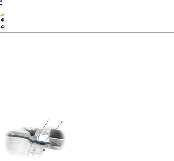
10. Remove the spring from the hook on the computer base by lifting it away with a screwdriver or a plastic scribe.

1 |
hook |
2 |
spring |
|
|
|
|
11. Remove the plastic battery-latch assembly by twisting the assembly slightly and lifting it out of the channel and away from the computer base.
1 |
battery latch assembly |
|
|
|
|
Replacing the Battery Latch Assembly
1.Insert the latch assembly into the channel on the computer base, and press it into place.
2.Using a small screwdriver, hook the spring over the hook on the computer base.
3.Place the battery latch release under the computer base, line it up with the hole in the base, and then replace the screw in the assembly.
Ensure that the newly installed latch moves smoothly and freely when pushed and released.
4.Replace the system board (see Replacing the System Board).
5.Replace the processor thermal-cooling assembly (see Replacing the Processor Thermal-Cooling Assembly).
6.Replace the palm rest (see Replacing the Palm Rest).
7.Replace the display assembly (see Replacing the Display Assembly).
8.Replace the keyboard (see Replacing the Keyboard).
9.Replace the hinge cover (see Replacing the Hinge Cover).
10.Replace the hard drive (see Replacing the Hard Drive).
Back to Contents Page

Back to Contents Page
Before You Begin
Dell™ Latitude™ 131L/
Dell Vostro™ 1000 Service Manual
Recommended Tools
Turning Off Your Computer
Before Working Inside Your Computer
This section provides procedures for removing and installing the components in your computer. Unless otherwise noted, each procedure assumes that the following conditions exist:
•You have performed the steps in Turning Off Your Computer and Before Working Inside Your Computer.
•You have read the safety information in the Dell™ Product Information Guide.
•A component can be replaced or—if purchased separately—installed by performing the removal procedure in reverse order.
Recommended Tools
The procedures in this document may require the following tools:
•Small flat-blade screwdriver
•Phillips screwdriver
•Small plastic scribe
•Hex-nut driver
•Flash BIOS update program CD
Turning Off Your Computer
NOTICE: To avoid losing data, save and close any open files and exit any open programs before you turn off your computer.
1.Shut down the operating system:
Save and close any open files, exit any open programs, click Start® Shut Down® Shut down.
The computer turns off after the operating system shutdown process finishes.
2.Ensure that the computer and any attached devices are turned off. If your computer and attached devices did not automatically turn off when you shut down your operating system, press and hold the power button until the computer turns off.
Before Working Inside Your Computer
Use the following safety guidelines to help protect your computer from potential damage and to help ensure your own personal safety.
CAUTION: Before you begin any of the procedures in this section, follow the safety instructions in the Product Information Guide.
NOTICE: Handle components and cards with care. Do not touch the components or contacts on a card. Hold a card by its edges or by its metal mounting bracket. Hold a component such as a processor by its edges, not by its pins.
NOTICE: Only a certified service technician should perform repairs on your computer. Damage due to servicing that is not authorized by Dell is not covered by your warranty.
NOTICE: When you disconnect a cable, pull on its connector or on its pull-tab, not on the cable itself. Some cables have a connector with locking tabs; if you are disconnecting this type of cable, press in on the locking tabs before you disconnect the cable. As you pull connectors apart, keep them evenly aligned to avoid bending any connector pins. Also, before you connect a cable, ensure that both connectors are correctly oriented and aligned.
NOTICE: To help prevent damage to the computer, perform the following steps before you begin working inside the computer.
1.Ensure that the work surface is flat and clean to prevent the computer cover from being scratched.
2.Turn off your computer (see Turning Off Your Computer).
NOTICE: To disconnect a network cable, first unplug the cable from your computer and then unplug it from the network device.
3.Disconnect any telephone or network cables from the computer.
4.Disconnect your computer and all attached devices from their electrical outlets.
5.Close the display and turn the computer upside-down on a flat work surface.
NOTICE: To help prevent damage to the system board, remove the main battery before working inside the computer.
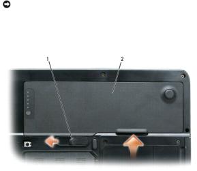
6.Slide the battery-bay latch release on the bottom of the computer.
7.Remove the battery from the battery bay.
1 |
battery-bay latch release |
2 |
main battery |
|
|
|
|
|
|
|
|
|
|
|
Back to Contents Page |
|
|
|
|

Back to Contents Page
Flashing the BIOS
Dell™ Latitude™ 131L/
Dell Vostro™ 1000 Service Manual
1. Ensure that the AC adapter is plugged in and that the main battery is installed properly.
NOTE: If you use a BIOS update program CD to flash the BIOS, set up the computer to boot from a CD before inserting the CD. The BIOS update program CD may not be available in your region.
2.Insert the BIOS update program CD, and turn on the computer.
Follow the instructions that appear on the screen. The computer continues to boot and updates the new BIOS. When the flash update is complete, the computer will automatically reboot.
3.Press <F2> during POST to enter the system setup program.
4.Press <Esc Suspend>, select Save changes and reboot, and press <Enter> to save configuration changes.
5.Remove the flash BIOS update program floppy or CD from the drive and restart the computer.
Back to Contents Page

Back to Contents Page
Bluetooth® Card
Dell™ Latitude™ 131L/
Dell Vostro™ 1000 Service Manual
Removing a Bluetooth Card
Replacing a Bluetooth Card
CAUTION: Before you begin any of the procedures in this section, follow the safety instructions in the Product Information Guide.
NOTICE: To avoid electrostatic discharge, ground yourself by using a wrist grounding strap or by periodically touching an unpainted metal surface (such as the back panel) on the computer.
NOTICE: To help prevent damage to the system board, you must remove the battery from the battery bay before you begin working inside the computer.
Removing a Bluetooth Card
1.Follow the procedures in Before You Begin.
2.Locate the Bluetooth card cover.
3.Press down on the cover's release latch.
4.Rotate the cover to release it from the chassis.
5.Disconnect the Bluetooth cable.
6.Slide the Bluetooth card from the Bluetooth card cover.
Replacing a Bluetooth Card
1.Slide the Bluetooth card into the Bluetooth card cover.
2.Connect the Bluetooth cable.
3.Align the Bluetooth card cover and press down firmly into place.
Back to Contents Page

Back to Contents Page
ExpressCard/Hard-Drive Bay Assembly
Dell™ Latitude™ 131L/
Dell Vostro™ 1000 Service Manual
Removing the ExpressCard/Hard-Drive Bay Assembly
Replacing the ExpressCard/Hard-Drive Bay Assembly
CAUTION: Before you begin the following procedure, follow the safety instructions in the Product Information Guide.
NOTICE: To avoid electrostatic discharge, ground yourself by using a wrist grounding strap or by periodically touching an unpainted metal surface (such as the back panel) on the computer.
NOTICE: To help prevent damage to the system board, remove the main battery (see Before Working Inside Your Computer) before working inside the computer.
Removing the ExpressCard/Hard-Drive Bay Assembly
1.Follow the instructions in Before You Begin.
2.Remove the hard drive (see Removing the Hard Drive).
3.Remove the optical drive (see Removing an Optical Drive).
4.Remove the hinge cover (see Removing the Hinge Cover).
5.Remove the keyboard (see Removing the Keyboard).
6.Remove the display assembly (see Removing the Display Assembly).
7.Remove the palm rest (see Removing the Palm Rest).
8.Remove the six M2.5x 5-mm screws from the ExpressCard/hard-drive bay assembly.
1 |
M2.5 x 5-mm screws (6) |
2 |
ExpressCard/hard-drive bay assembly |
|
|
|
|
9. Remove the assembly from the system board.
Replacing the ExpressCard/Hard-Drive Bay Assembly
1.At a 45-degree angle, insert the end of the ExpressCard/hard-drive bay assembly into its access hole on the side of the computer base.
2.Lower the assembly aligning the screw holes on the assembly with the holes on the system board.
3.Replace the six M2.5x 5-mm screws from the assembly.

Back to Contents Page

Back to Contents Page
Mini-Card
Dell™ Latitude™ 131L/
Dell Vostro™ 1000 Service Manual
Removing a Mini-Card
Replacing a Mini-Card
If you ordered a Mini-Card with your computer, the card is already installed.
CAUTION: Before you begin any of the procedures in this section, follow the safety instructions in the Product Information Guide.
NOTICE: To avoid electrostatic discharge, ground yourself by using a wrist grounding strap or by periodically touching an unpainted metal surface (such as the back panel) on the computer.
NOTICE: To help prevent damage to the system board, you must remove the battery from the battery bay before you begin working inside the computer.
Removing a Mini-Card
1.Follow the procedures in Before You Begin.
2.Remove the hinge cover (see Removing the Hinge Cover).
3.Remove the keyboard (see Removing the Keyboard).
4.Disconnect the two antenna cables from the Mini-Card.
1 |
Mini-Card |
2 |
antenna cables (2) |
|
|
|
|
5.Release the Mini-Card by pushing the metal securing tabs toward the back of the computer until the card pops up slightly.
6.Lift the Mini-Card out of its system board connector.
1 |
metal securing tab |
2 |
Mini-Card |
3 |
metal securing tab |
|
|
|
|
|
|
|
|
Replacing a Mini-Card
NOTICE: The system board and Mini-Card connectors are keyed to ensure correct insertion. If you feel resistance, check the connectors on the card and on the system board, and realign the card.
NOTICE: Make sure the antenna cables are not under the card when you insert it.
1. Insert the Mini-Card connector into the system board connector at a 45-degree angle.
2.Press the other end of the Mini-Card into the securing tabs until the card clicks into place.
3.Connect the black antenna cable to the connector labeled with a black triangle, and connect the white antenna cable to the connector labeled with a white triangle.
 1
1  Mini-Card
  2
2  white antenna cable (white triangle)
  3
3  black antenna cable (black triangle)
Back to Contents Page

Back to Contents Page
Coin-Cell Battery
Dell™ Latitude™ 131L/
Dell Vostro™ 1000 Service Manual
Removing the Coin-Cell Battery
Replacing the Coin-Cell Battery
CAUTION: Before you begin the following procedure, follow the safety instructions in the Product Information Guide.
NOTICE: To avoid electrostatic discharge, ground yourself by using a wrist grounding strap or by periodically touching an unpainted metal surface (such as the back panel) on the computer.
NOTICE: To help prevent damage to the system board, remove the main battery (see Before Working Inside Your Computer) before working inside the computer.
Removing the Coin-Cell Battery
1.Follow the instructions in Before You Begin.
2.Remove the hinge cover (see Removing the Hinge Cover).
3.Remove the keyboard (see Removing the Keyboard).
4.Insert a plastic scribe into the guide on the side of the coin-cell battery compartment, and pry out the battery.
Replacing the Coin-Cell Battery
1.When you replace the battery, insert it at a 30-degree angle under the clip with the positive (identified by a plus [+] symbol) side up, and then push it into place.
2.Replace the keyboard (see Replacing the Keyboard).
3.Replace the hinge cover (see Replacing the Hinge Cover).
Back to Contents Page

Back to Contents Page
Processor Thermal-Cooling Assembly
Dell™ Latitude™ 131L/
Dell Vostro™ 1000 Service Manual
Removing the Processor Thermal-Cooling Assembly
Replacing the Processor Thermal-Cooling Assembly
CAUTION: Before you begin the following procedure, follow the safety instructions in the Product Information Guide.
NOTICE: To avoid electrostatic discharge, ground yourself by using a wrist grounding strap or by periodically touching an unpainted metal surface (such as the back panel) on the computer.
NOTICE: To help prevent damage to the system board, remove the main battery (see Before Working Inside Your Computer) before working inside the computer.
Removing the Processor Thermal-Cooling Assembly
1.Follow the instructions in Before You Begin.
2.Remove the hinge cover (see Removing the Hinge Cover).
3.Remove the keyboard (see Removing the Keyboard).
4.Remove the display assembly (see Removing the Display Assembly).
5.Remove the palm rest (see Removing the Palm Rest).
6.Loosen in consecutive order the four captive screws, labeled "1" through "4," that secure the processor thermal-cooling assembly to the system board.
NOTICE: To ensure maximum cooling for the processor, do not touch the heat transfer areas on the processor thermal-cooling assembly. The oils in your skin reduce the heat transfer capability of the thermal pads.
7. Lift the processor thermal-cooling assembly and remove it from the system board.
1 |
captive screws (4) |
2 |
processor thermal-cooling assembly |
|
|
|
|
|
|
|
|
|
|
|
Replacing the Processor Thermal-Cooling Assembly
NOTE: If you are replacing the thermal-cooling assembly without removing and replacing a new processor, you can place the new thermal pad directly on any existing thermal pad already installed on the thermal-cooling assembly. It is not necessary to remove an existing pad or to clean the surface.
1.Place the processor thermal-cooling assembly over the processor.
2.Tighten the four captive screws, labeled "1" through "4," in consecutive order.
Back to Contents Page
 Loading...