


Dell™ Inspiron™ 1420/Dell Vostro™ 1400
Service Manual
Before You Begin |
Display |
Internal Card With Bluetooth® Wireless Technology |
Camera Module |
Optical Drive |
Palm Rest |
Hard Drive |
Fan |
Memory |
Microprocessor Thermal-Cooling Assembly |
Modem |
Microprocessor Module |
Coin-Cell Battery |
System Board |
Keyboard Cover |
Speakers |
Keyboard |
Flashing the BIOS |
Communication Cards |
Pin Assignments for I/O Connectors |
Intel® Turbo Memory |
|
|
|
Notes, Notices, and Cautions
NOTE: A NOTE indicates important information that helps you make better use of your computer.
NOTICE: A NOTICE indicates either potential damage to hardware or loss of data and tells you how to avoid the problem. CAUTION: A CAUTION indicates a potential for property damage, personal injury, or death.
NOTE: The appearance of your computer may vary from what is shown in this document.
Information in this document is subject to change without notice.
© 2007 Dell Inc. All rights reserved.
Reproduction in any manner whatsoever without the written permission of Dell Inc. is strictly forbidden.
Trademarks used in this text: Dell, the DELL logo, Inspiron, and Vostro are trademarks of Dell Inc.; Intel is a registered trademark of Intel Corporation; Microsoft, Windows, and Windows Vista are either trademarks or registered trademarks of Microsoft Corporation in the United States and/or other countries; Bluetooth is a registered trademark owned by Bluetooth SIG, Inc. and is used by Dell under license.
Other trademarks and trade names may be used in this document to refer to either the entities claiming the marks and names or their products. Dell Inc. disclaims any proprietary interest in trademarks and trade names other than its own.
September 2009 Rev. A01
Back to Contents Page
Before You Begin
Dell™ Inspiron™ 1420/Dell Vostro™ 1400
Service Manual
Recommended Tools
Turning Off Your Computer
Before Working Inside Your Computer
This section provides procedures for removing and installing the components in your computer. Unless otherwise noted, each procedure assumes that the following conditions exist:
•You have performed the steps in Turning Off Your Computer and Before Working Inside Your Computer.
•You have read the safety information in the Dell™ Product Information Guide.
•A component can be replaced or—if purchased separately—installed by performing the removal procedure in reverse order.
Recommended Tools
The procedures in this document may require the following tools:
•Small flat-blade screwdriver
•Small Phillips screwdriver
•Small plastic scribe
•Flash BIOS update program CD
Turning Off Your Computer
NOTICE: To avoid losing data, save and close all open files and exit all open programs before you turn off your computer.
1.Shut down the operating system:
a.Save and close all open files and exit all open programs.
b.Click the Windows Vista Start button  , click the arrow in the lower-right corner of the Start menu as shown below, and then click Shut Down.
The computer turns off after the operating system shutdown process is complete.
2.Ensure that the computer and all attached devices are turned off. If your computer and attached devices did not automatically turn off when you shut down your operating system, press and hold the power button for about 4 seconds to turn them off.
Before Working Inside Your Computer
Use the following safety guidelines to help protect your computer from potential damage and to help to ensure your own personal safety.
CAUTION: Before you begin any of the procedures in this section, follow the safety instructions in the Product Information Guide.
CAUTION: Many repairs may only be done by a certified service technician. You should only perform troubleshooting and simple repairs as authorized in your product documentation, or as directed by the online or telephone service and support team. Damage due to servicing that is not authorized by Dell is not covered by your warranty. Read and follow the safety instructions that came with the product.
NOTICE: Handle components and cards with care. Do not touch the components or contacts on a card. Hold a card by its edges or by its metal mounting bracket. Hold a component such as a processor by its edges, not by its pins.
NOTICE: When you disconnect a cable, pull on its connector or on its pull-tab, not on the cable itself. Some cables have connectors with locking tabs; if you are disconnecting this type of cable, press in on the locking tabs before you disconnect the cable. As you pull connectors apart, keep them evenly aligned to avoid bending any connector pins. Also, before you connect a cable, ensure that both connectors are correctly oriented and aligned.
NOTICE: To avoid damaging the computer, perform the following steps before you begin working inside the computer.
1.Ensure that the work surface is flat and clean to prevent the computer cover from being scratched.
2.Turn off your computer (see Turning Off Your Computer).
NOTICE: To disconnect a network cable, first unplug the cable from your computer and then unplug the cable from the network device.
3. Disconnect all telephone or network cables from the computer.
NOTICE: To avoid damaging the system board, you must remove the main battery before you service the computer.
4.Disconnect your computer and all attached devices from their electrical outlets.
5.Close the display and turn the computer upside-down on a flat work surface.
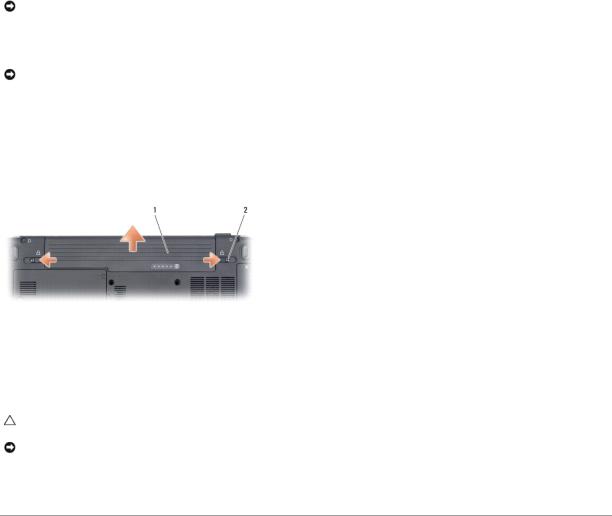
6.Slide the battery release latches toward the sides of the computer until they are engaged.
7.Slide the battery out of the bay.
1 |
battery |
2 |
battery release latches (2) |
|
|
|
|
8.Open the display.
9.Press the power button to ground the system board.
CAUTION: To guard against electrical shock, always unplug your computer from the electrical outlet before opening the display.
NOTICE: Before touching anything inside your computer, ground yourself by touching an unpainted metal surface, such as the metal at the back of the computer. While you work, periodically touch an unpainted metal surface to dissipate static electricity, which could harm internal components.
10. Remove any installed cards from the ExpressCard slot and the 8-in-1 memory card reader.
Back to Contents Page

Back to Contents Page
Flashing the BIOS
Dell™ Inspiron™ 1420/Dell Vostro™ 1400
Service Manual
1.Download the BIOS utility from the Dell Support website at support.dell.com and save it to your desktop.
2.After the download completes, double-click the BIOS utility file.
3.In the Dell BIOS Flash window, click Continue.
4.When the reboot message appears, click OK and wait for the computer to restart.
Back to Contents Page
Back to Contents Page
Internal Card With Bluetooth® Wireless Technology
Dell™ Inspiron™ 1420/Dell Vostro™ 1400
Service Manual
Removing and Replacing Internal Card With Bluetooth® Wireless Technology
CAUTION: Before you begin any of the procedures in this section, follow the safety instructions in the Product Information Guide.
NOTICE: To help prevent damage to the system board, you must remove the battery from the battery bay before you begin working inside the computer.
Removing and Replacing Internal Card With Bluetooth® Wireless Technology
CAUTION: Before performing the following procedures, follow the safety instructions in your Product Information Guide.
NOTICE: To avoid electrostatic discharge, ground yourself by using a wrist grounding strap or by periodically touching a connector on the back panel of the computer.
If you ordered an internal card with Bluetooth wireless technology with your computer, it is already installed.
1.Follow the procedures in Before You Begin.
2.Remove the memory module cover (see Memory).
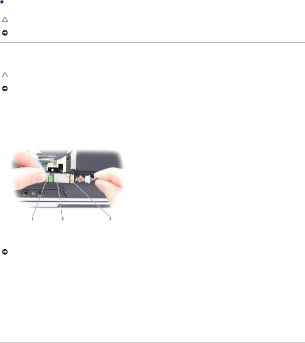
1 |
metal clip |
2 |
internal card with Bluetooth wireless technology |
3 |
captive screw |
|
|
|
|
|
|
NOTICE: Be careful when removing the card to avoid damaging the card, card cable, or surrounding components.
3.Using a Phillips screwdriver, remove the screw securing the Bluetooth card to the chassis.
4.While grasping the card cable with one hand, use a plastic scribe to gently pry and lift the Bluetooth card up and out of the communications card bay.
5.Disconnect the card from the card cable.
6.Connect the replacement card to the card cable.
7.Slide the card underneath the metal clips.
8.Tighten the captive screw to secure the card carrier.
Back to Contents Page

Back to Contents Page
Camera Module
Dell™ Inspiron™ 1420/Dell Vostro™ 1400
Service Manual
Removing and Replacing the Camera Module
Removing and Replacing the Camera Module
CAUTION: Before you perform any of the procedures in this section, follow the safety instructions in the Product Information Guide.
NOTICE: To avoid electrostatic discharge, ground yourself by using a wrist grounding strap or by periodically touching an unpainted metal surface, such as the back panel on the computer.
1.Follow the instructions in Before You Begin.
2.Remove the display bezel (see Removing the Display Bezel).
3.Lift the cable securing tab, and then gently pull the camera module cable from the connector.
4.Remove the two M2 x 3-mm screws securing camera module to the display assembly.
5.Gently lift the camera module.
6.Install the replacement camera and tighten the two M2 x 3-mm screws.
7.Insert the camera module cable in the connector and press down the securing tab.
8.Replace the display bezel (see Replacing the Display Bezel).
1 |
display |
2 |
screws (2) |
|
|
|
|
|
|
3 |
camera |
4 |
camera module |
|
|
|
|
|
|
|
|
|
|
|
Back to Contents Page

Back to Contents Page
Coin-Cell Battery
Dell™ Inspiron™ 1420/Dell Vostro™ 1400
Service Manual
Removing the Coin-Cell Battery
Replacing the Coin-Cell Battery
CAUTION: Before you begin any of the procedures in this section, follow the safety instructions in the Product Information Guide.
NOTICE: To avoid electrostatic discharge, ground yourself by using a wrist grounding strap or by periodically touching an unpainted metal surface (such as a connector on the back of the computer).
NOTICE: To help prevent damage to the system board, you must remove the battery from the battery bay before you begin working inside the computer.
Removing the Coin-Cell Battery
1.Follow the procedures in Before You Begin.
2.Turn the computer over.
3.Loosen the captive screws on the coin-cell battery cover and remove the cover.
4.Remove the modem (see Modem).
1 |
coin-cell battery |
2 |
battery cable connector |
|
|
|
|
NOTE: The coin-cell battery is secured to the system board with double-sided tape.
5.Lift the coin-cell battery up and off the system board.
6.Remove the tape securing the coin-cell battery to the system board.
7.Disconnect and remove the coin-cell battery cable from the power connector on the system board.
Replacing the Coin-Cell Battery
1.Connect the coin-cell battery cable to the system board.
2.Place the coin-cell battery on the system board in the location marked  .
.
3.Replace the modem (see Modem).
4.Replace the cover and tighten the captive screws.

Back to Contents Page
Back to Contents Page
Microprocessor Module
Dell™ Inspiron™ 1420/Dell Vostro™ 1400
Service Manual
Removing the Microprocessor Module
Replacing the Microprocessor Module
Removing the Microprocessor Module
CAUTION: Before you perform any of the procedures in this section, follow the safety instructions in the Product Information Guide.
NOTICE: To avoid electrostatic discharge, ground yourself by using a wrist grounding strap or by periodically touching an unpainted metal surface, such as the back panel on the computer.
NOTICE: Handle the microprocessor module with care. Hold the microprocessor module by its edges and do not touch the processor die (the small chip in the center of the module).
1.Follow the instructions in Before You Begin.
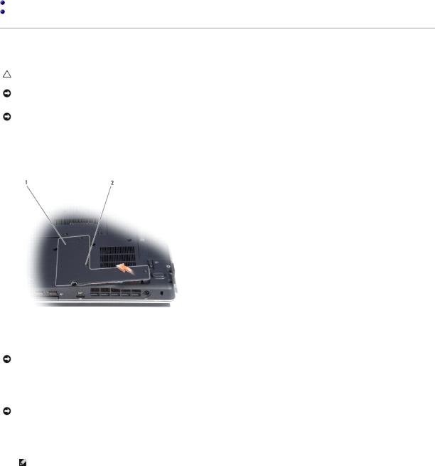
2.Loosen the three captive screws securing the microprocessor module cover, then remove the cover and set it aside.
1 |
microprocessor module cover |
2 |
captive screw (3) |
NOTICE: To ensure maximum cooling for the microprocessor, do not touch the heat transfer areas on the microprocessor thermal-cooling assembly. Oils in your skin can reduce the heat transfer capability of the thermal pads.
3. Remove the microprocessor thermal-cooling assembly (see Removing the Microprocessor Thermal-Cooling Assembly).
NOTICE: To avoid damaging the microprocessor, hold the screwdriver so that it is perpendicular to the microprocessor module when turning the cam screw.
4.To loosen the ZIF-socket cam lock, use a small, flat-blade screwdriver and rotate the ZIF-socket cam screw counterclockwise until it comes to the cam stop.
NOTE: The ZIF-socket cam screw secures the microprocessor module to the system board.

1 |
microprocessor module |
2 |
ZIF-socket |
3 |
ZIF-socket cam screw |
|
|
|
|
|
|
NOTICE: When removing the microprocessor module, pull the module straight up and out of the ZIF-socket. Exercise care not to bend the pins on the microprocessor module.
NOTE: The microprocessor module and the ZIF-socket illustration shown may not exactly resemble the ones in your system.
5. Lift the microprocessor module straight up and out of the ZIF-socket.
Replacing the Microprocessor Module
CAUTION: Before you perform any of the procedures in this section, follow the safety instructions in the Product Information Guide.
NOTICE: To avoid electrostatic discharge, ground yourself by using a wrist grounding strap or by periodically touching an unpainted metal surface, such as the back panel on the computer.
NOTE: When installing a new microprocessor module, use the thermal cooling assembly or thermal pad that came with the module, if applicable.
1. Follow the instructions in Before You Begin.
NOTICE: Handle the microprocessor module with care. Hold the microprocessor module by its edges and do not touch the processor die (the small chip in the center of the module).
2. Follow the instructions in Removing the Microprocessor Module.
NOTICE: Ensure that the cam lock is in the fully open position before seating the microprocessor module. Seating the microprocessor module properly in the ZIF socket does not require force. A microprocessor module that is not properly seated can result in an intermittent connection or permanent damage to the microprocessor and ZIF socket.
3. Align the pin-1 corner of the new microprocessor module with the pin-1 corner of the ZIF socket, and insert the microprocessor module.
NOTE: The pin-1 corner of the microprocessor module has a triangle that aligns with the triangle on the pin-1 corner of the ZIF socket.
NOTE: Gently press down on the substrate on which the processor die is mounted to ensure the microprocessor module is properly seated.
When the microprocessor module is properly seated, all four corners of the module are aligned at the same height. If one or more corners of the module is higher than the others, the module is not properly seated.
NOTICE: To avoid damaging the microprocessor, hold the screwdriver so that it is perpendicular to the microprocessor module when turning the cam screw.
4.To tighten the ZIF-socket cam lock and secure the microprocessor module to the system board, use a small, flat-blade screwdriver and rotate the ZIFsocket cam screw clockwise until it comes to the cam stop.
5.Replace the microprocessor thermal-cooling assembly (see Replacing the Microprocessor Thermal-Cooling Assembly).
6.Replace the microprocessor module cover.
7.Update the BIOS using a flash BIOS update program floppy disk or CD. For instructions on how to flash the BIOS, see Flashing the BIOS.
Back to Contents Page

Back to Contents Page
Microprocessor Thermal-Cooling Assembly
Dell™ Inspiron™ 1420/Dell Vostro™ 1400
Service Manual
Removing the Microprocessor Thermal-Cooling Assembly
Replacing the Microprocessor Thermal-Cooling Assembly
Removing the Microprocessor Thermal-Cooling Assembly
CAUTION: Before you perform any of the procedures in this section, follow the safety instructions in the Product Information Guide.
NOTICE: To avoid electrostatic discharge, ground yourself by using a wrist grounding strap or by periodically touching an unpainted metal surface, such as the back panel on the computer.
1.Follow the instructions in Before You Begin.
2.Loosen the three captive screws securing the microprocessor module cover, then remove the cover and set it aside.
1 |
microprocessor module cover |
2 |
captive screws (3) |
|
|
|
|
3.Loosen the four captive screws securing the microprocessor thermalcooling assembly to the system board, then carefully lift the assembly straight out of the computer.
1 |
microprocessor thermal-cooling assembly |
2 |
screws (4) |
|
|
|
|
|
|
|
|
|
|
|
Replacing the Microprocessor Thermal-Cooling Assembly
CAUTION: Before you perform any of the procedures in this section, follow the safety instructions in the Product Information Guide.

NOTICE: To avoid electrostatic discharge, ground yourself by using a wrist grounding strap or by periodically touching an unpainted metal surface, such as the back panel on the computer.
1.Follow the instructions in Before You Begin.
2.Follow the instructions in Replacing the Microprocessor Module.
3.Align the four captive screws on the new microprocessor thermal-cooling assembly with the screw holes on the system board.
4.Tighten the four captive screws in the order that they are numbered to secure the microprocessor thermal-cooling assembly to the system board.
5.Replace the microprocessor module cover.
Back to Contents Page
Back to Contents Page
Display
Dell™ Inspiron™ 1420/Dell Vostro™ 1400
Service Manual
Removing the Display Assembly
Replacing the Display Assembly
Removing the Display Bezel
Replacing the Display Bezel
Removing the Display Panel
Replacing the Display Panel
Removing the Display Assembly
CAUTION: Before you perform any of the procedures in this section, follow the safety instructions in the Product Information Guide.
NOTICE: To avoid electrostatic discharge, ground yourself by using a wrist grounding strap or by periodically touching an unpainted metal surface, such as the back panel on the computer.
1.Follow the instructions in Before You Begin.
2.Remove the four M2.5 x 5-mm screws (one on each side of the main battery bay and one below each hinge cover) that connect the display assembly to the computer.
3.Remove the keyboard cover (see Removing the Keyboard Cover).
4.Remove the keyboard (see Removing the Keyboard).
5.Lift the cable securing tab for the camera module cable, and then gently pull the camera module cable from the connector.
6.Using a plastic scribe, pry out the left and right hinge covers.
7.Ensure that the display is opened all the way (150 degrees).
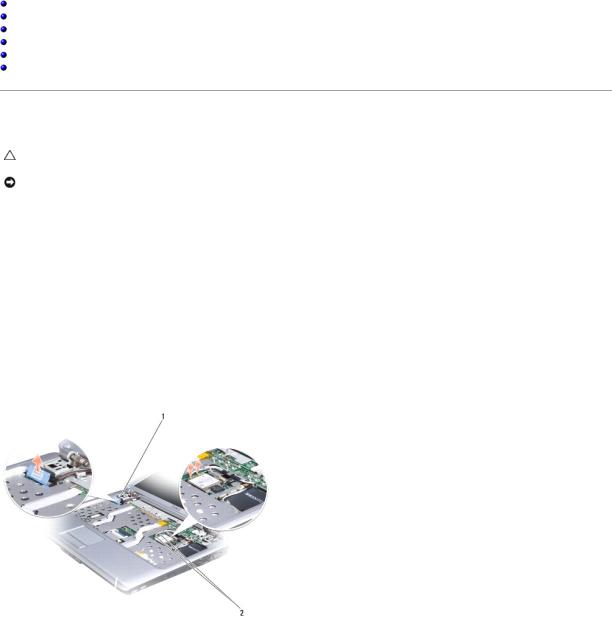
1 |
display cable pull-tab |
2 |
Mini-Card antenna cables |
8.Use the pull-tab to disconnect the display cable from the system board.
9.Remove the Mini-Card antenna cables from the cards.
10.Remove the Mini-Card antenna cables from the cable guide.
11.Remove the screw from the media buttons board.
 Loading...