


Dell Studio™ 1555 Service Manual
Before You Begin |
Speaker Assembly |
Base Cover |
Optical Drive |
Hard Drive |
ExpressCard Board |
Memory |
AC Adapter Connector |
Communication Cards |
USB Connector |
Coin-Cell Battery |
System Board Assembly |
Center Control Cover |
Processor Heat Sink |
Keyboard |
Processor Module |
Display |
Fan |
Power Button Board |
Subwoofer Assembly |
Camera (Optional) |
Battery Latch Assembly |
Palm Rest |
Flashing the BIOS |
|
|
Notes, Cautions, and Warnings
NOTE: A NOTE indicates important information that helps you make better use of your computer.
CAUTION: A CAUTION indicates potential damage to hardware or loss of data if instructions are not followed.
WARNING: A WARNING indicates a potential for property damage, personal injury, or death.
Information in this document is subject to change without notice.
© 2008 Dell Inc. All rights reserved.
Reproduction of these materials in any manner whatsoever without the written permission of Dell Inc. is strictly forbidden.
Trademarks used in this text: Dell and the DELL logo are trademarks of Dell Inc.; Bluetooth is a registered trademark owned by Bluetooth SIG, Inc. and is used by Dell under license; Microsoft, Windows, Windows Vista, and Windows Vista start button logo are either trademarks or registered trademarks of Microsoft Corporation in the United States and/or other countries.
Other trademarks and trade names may be used in this document to refer to either the entities claiming the marks and names or their products. Dell Inc. disclaims any proprietary interest in trademarks and trade names other than its own.
Model PP39L
December 2008 Rev. A00

Back to Contents Page
Base Cover
Dell Studio™ 1555 Service Manual
Removing the Base Cover
Replacing the Base Cover
WARNING: Before working inside your computer, read the safety information that shipped with your computer. For additional safety best practices information, see the Regulatory Compliance Homepage at www.dell.com/regulatory_compliance.
WARNING: Before performing these procedures, turn off the computer, disconnect the AC adapter from the electrical outlet and the computer, disconnect the modem from the wall connector and the computer, and remove any other external cables from the computer.
CAUTION: To avoid electrostatic discharge, ground yourself by using a wrist grounding strap or by periodically touching an unpainted metal surface (such as a connector on the back of the computer).
CAUTION: Only a certified service technician should perform repairs on your computer. Damage due to servicing that is not authorized by Dell™ is not covered by your warranty.
CAUTION: To help prevent damage to the system board, remove the main battery (see "Before Working Inside Your Computer" on page 10) before working inside the computer.
Removing the Base Cover
1.Ensure that the computer is turned off.
2.Remove the battery (see Before Working Inside Your Computer).
3.Loosen the three captive screws on the base cover and lift the cover off the computer at an angle as shown in the figure.
1 base cover |
2 tabs |
3 captive screws (3)
Replacing the Base Cover
1.Align the tabs on the base cover to the bottom of the computer.
2.Tighten the three captive screws on the base cover.
3.Slide the battery into the battery bay until it clicks into place.
Back to Contents Page

Back to Contents Page
Before You Begin
Dell Studio™ 1555 Service Manual
Recommended Tools
Turning Off Your Computer
Before Working Inside Your Computer
This document provides procedures for removing and installing the components in your computer. Unless otherwise noted, each procedure assumes that:
•You have performed the steps in Before Working Inside Your Computer.
•You have read the safety information that shipped with your computer.
•When replacing a component, you have already removed the original component, if installed.
Recommended Tools
The procedures in this document may require the following tools:
•Small flat-blade screwdriver
•Phillips screwdriver
•Small plastic scribe
•BIOS upgrade CD (see the Dell Support website at support.dell.com)
Turning Off Your Computer
CAUTION: To avoid losing data, save and close all open files and exit all open programs before you turn off your computer.
1.Save and close all open files and exit all open programs.
2.In Microsoft® Windows Vista®, click Start  , click the arrow
  , and then click Shut Down.
The computer turns off after the operating system shutdown process finishes.
3.Ensure that the computer and any attached devices are turned off. If your computer and attached devices did not automatically turn off when you shut down your operating system, press and hold the power button for at least 8 to 10 seconds until the computer turns off.
Before Working Inside Your Computer
Use the following safety guidelines to help protect your computer from potential damage and to help ensure your own personal safety.
WARNING: Before working inside your computer, read the safety information that shipped with your computer. For additional safety best practices information, see the Regulatory Compliance Homepage at www.dell.com/regulatory_compliance.
CAUTION: Only a certified service technician should perform repairs on your computer. Damage due to servicing that is not authorized by Dell is not covered by your warranty.
CAUTION: To avoid electrostatic discharge, ground yourself by using a wrist grounding strap or by periodically touching an unpainted metal surface, such as a connector on the back of the computer.
CAUTION: Handle components and cards with care. Do not touch the components or contacts on a card. Hold a card by its edges. Hold a component such as a processor by its edges, not by its pins.
CAUTION: When disconnecting a cable, pull on the cable's connector or on its pull-tab, not on the cable itself. For cable connectors with locking tabs, press inward on the locking tabs to release the connector. When connecting a cable, ensure that the connectors are correctly oriented and aligned to avoid damage to the connector and/or the connector's pins.
1.Ensure that the work surface is flat and clean to prevent the computer cover from being scratched.
2.Turn off your computer (see Turning Off Your Computer).

CAUTION: To disconnect a network cable, first unplug the cable from your computer, and then unplug it from the network device.
3.Disconnect any telephone or network cables from the computer.
4.Press and eject any installed cards from the ExpressCard slot and the 8-in-1 Memory Card Reader.
CAUTION: To help prevent damage to the system board, you must remove the battery from the battery bay before you service the computer.
CAUTION: To avoid damage to the computer, use only the battery designed for this particular Dell computer. Do not use batteries designed for other Dell computers.
5.Turn the computer over.
6.Slide the battery release latch until it clicks into place.
7.Slide the battery out of the battery bay.
 1
1  battery
  2
2  battery release latch
8. Turn the computer top side up, open the display, and press the power button to ground the system board.
Back to Contents Page

Back to Contents Page
Flashing the BIOS
Dell Studio™ 1555 Service Manual
Flashing the BIOS From a CD
Flashing the BIOS From the Hard Drive
If a BIOS upgrade CD is provided with the new processor or new system board, flash the BIOS from the CD. If you do not have a BIOS upgrade CD, flash the BIOS from the hard drive.
Flashing the BIOS From a CD
CAUTION: Plug the AC adapter into a known, good power source to prevent loss of power. Failure to do so may cause system damage.
1. Ensure that the AC adapter is plugged in and that the main battery is installed properly.
NOTE: If you use the BIOS-update program CD to flash the BIOS, press <F12> before inserting the CD so that you can set up the computer to boot from a CD for one time only. Otherwise, you must enter the system setup program to change the default boot order.
2. Insert the BIOS-update program CD and turn on the computer.
CAUTION: Do not interrupt this process once it begins. Doing so may cause damage to the computer.
Follow the instructions that appear on the screen. The computer continues to boot and updates the new BIOS. When the flash update is complete, the computer will automatically reboot.
3.Press <F2> during POST to enter the system setup program.
4.Press <Alt> and <f> to reset the computer defaults.
5.Press <Esc>, select Save/Exit, and press <Enter> to save configuration changes.
6.Remove the flash BIOS-update program CD from the drive and restart the computer.
Flashing the BIOS From the Hard Drive
CAUTION: Plug the AC adapter into a known, good power source to prevent loss of power. Failure to do so may cause damage to the computer.
1.Ensure that the AC adapter is plugged in, the main battery is properly installed, and a network cable is attached.
2.Turn on the computer.
3.Locate the latest BIOS update file for your computer at support.dell.com.
4.Click Download Now to download the file.
5.If the Export Compliance Disclaimer window appears, click Yes, I Accept this Agreement.
The File Download window appears.
6.Click Save this program to disk, and then click OK.
The Save In window appears.
7.Click the down arrow to view the Save In menu, select Desktop, and then click Save.
The file downloads to your desktop.
8.Click Close if the Download Complete window appears.
The file icon appears on your desktop and is titled the same as the downloaded BIOS update file.

CAUTION: Do not interrupt this process once it begins. Doing so may cause system damage.
9. Double-click the file icon on the desktop and follow the instructions on the screen.
Back to Contents Page
Back to Contents Page
Camera (Optional)
Dell Studio™ 1555 Service Manual
Removing the Camera Module
Replacing the Camera Module
WARNING: Before working inside your computer, read the safety information that shipped with your computer. For additional safety best practices information, see the Regulatory Compliance Homepage at www.dell.com/regulatory_compliance.
CAUTION: To avoid electrostatic discharge, ground yourself by using a wrist grounding strap or by periodically touching an unpainted metal surface (such as a connector on the back of the computer).
CAUTION: Only a certified service technician should perform repairs on your computer. Damage due to servicing that is not authorized by Dell™ is not covered by your warranty.
CAUTION: To help prevent damage to the system board, remove the main battery (see Before Working Inside Your Computer) before working inside the computer.
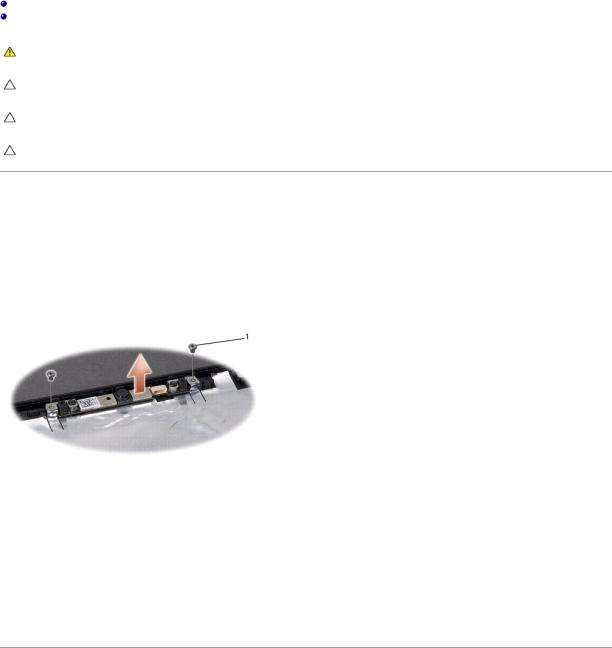
Removing the Camera Module
1.Follow the instructions in Before You Begin.
2.Remove the display panel (see Removing the Display Panel).
3.Remove the two screws that secure the camera to the display cover.
4.Lift the camera board from the display cover.
1 |
screws (2) |
|
|
|
|
|
|
|
Replacing the Camera Module
1.Follow the instructions in Before You Begin.
2.Replace and tighten the two screws securing the camera to the display cover.
3.Replace the display panel (see Replacing the Display Panel).
Back to Contents Page

Back to Contents Page
Center Control Cover
Dell Studio™ 1555 Service Manual
Removing the Center Control Cover
Replacing the Center Control Cover
WARNING: Before working inside your computer, read the safety information that shipped with your computer. For additional safety best practices information, see the Regulatory Compliance Homepage at www.dell.com/regulatory_compliance.
CAUTION: To avoid electrostatic discharge, ground yourself by using a wrist= grounding strap or by periodically touching an unpainted metal surface (such as a connector on the back of the computer).
CAUTION: Only a certified service technician should perform repairs on your computer. Damage due to servicing that is not authorized by Dell™ is not covered by your warranty.
CAUTION: To help prevent damage to the system board, remove the main battery (see Before Working Inside Your Computer) before working inside the computer.
Removing the Center Control Cover
1.Follow the procedures in Before You Begin.
2.Remove the screw securing the center control cover from the battery bay.
3.Turn the computer over and open the display as far as possible.
4.Pry out the center control cover with a plastic scribe starting from the battery bay location at the back of the computer.
5.Ease the center control cover up.
1 |
center control cover |
|
|
|
|
|
|
|

Replacing the Center Control Cover
1.Follow the procedures in Before You Begin.
2.Align the hooks beneath the center control cover to the slots on the palm rest and snap the cover in place.
3.Close the display and turn over the computer.
4.In the battery bay, replace the screw that secures the center control cover.
5.Slide the battery into the battery bay until it clicks into place.
Back to Contents Page

Back to Contents Page
Coin-Cell Battery
Dell Studio™ 1555 Service Manual
Removing the Coin-Cell Battery
Replacing the Coin-Cell Battery
WARNING: Before working inside your computer, read the safety information that shipped with your computer. For additional safety best practices information, see the Regulatory Compliance Homepage at www.dell.com/regulatory_compliance.
CAUTION: To avoid electrostatic discharge, ground yourself by using a wrist= grounding strap or by periodically touching an unpainted metal surface (such as a connector on the back of the computer).
CAUTION: Only a certified service technician should perform repairs on your computer. Damage due to servicing that is not authorized by Dell™ is not covered by your warranty.
CAUTION: To help prevent damage to the system board, remove the main battery (see Before Working Inside Your Computer) before working inside the computer.
Removing the Coin-Cell Battery
1.Follow the instructions in Before You Begin.
2.Remove the base cover (see Removing the Base Cover).
3.Use a plastic scribe to pry up the coin-cell battery from the slot.
 1
1  coin-cell battery
  2
2  plastic scribe
Replacing the Coin-Cell Battery
1.Follow the instructions in Before You Begin.
2.Hold the coin-cell battery with the positive side up.
3.Slide the coin-cell battery into the slot and gently press until it snaps to the slot.
4.Replace the base cover (see Replacing the Base Cover).
Back to Contents Page
Back to Contents Page
Processor Module
Dell Studio™ 1555 Service Manual
Removing the Processor Module
Replacing the Processor Module
WARNING: Before working inside your computer, read the safety information that shipped with your computer. For additional safety best practices information, see the Regulatory Compliance Homepage at www.dell.com/regulatory_compliance.
CAUTION: To avoid electrostatic discharge, ground yourself by using a wrist grounding strap or by periodically touching an unpainted metal surface (such as the back panel) on the computer.
CAUTION: To prevent intermittent contact between the ZIF-socket cam screw and the processor when removing or replacing the processor, press to apply slight pressure to the center of the processor while turning the cam screw.
CAUTION: To avoid damage to the processor, hold the screwdriver so that it is perpendicular to the processor when turning the cam screw.
CAUTION: Only a certified service technician should perform repairs on your computer. Damage due to servicing that is not authorized by Dell™ is not covered by your warranty.
CAUTION: To help prevent damage to the system board, remove the main battery (see Before Working Inside Your Computer) before working inside the computer.
Removing the Processor Module
1.Follow the instructions in Before You Begin.
2.Remove the processor heat sink (see Removing the Processor Heat Sink).
3.To loosen the ZIF socket, use a small, flat-blade screwdriver and rotate the ZIF-socket cam screw counterclockwise until it comes to the cam stop.
 1
1  ZIF-socket cam screw
  2
2  ZIF socket
CAUTION: To ensure maximum cooling for the processor, do not touch the heat transfer areas on the processor thermal-cooling assembly. The oils in your skin can reduce the heat transfer capability of the thermal pads.
CAUTION: When removing the processor module, pull the module straight up. Be careful not to bend the pins on the processor module.
4. Lift the processor module from the ZIF socket.
Replacing the Processor Module

NOTE: If a new processor is installed, you will receive a new thermal-cooling assembly, which will include an affixed thermal pad, or you will receive a new thermal pad along with documentation to illustrate proper installation.
1.Follow the instructions in Before You Begin.
2.Align the pin-1 corner of the processor module with the pin-1 corner of the ZIF socket, then insert the processor module.
NOTE: The pin-1 corner of the processor module has a triangle that aligns with the triangle on the pin-1 corner of the ZIF socket.
When the processor module is properly seated, all four corners are aligned at the same height. If one or more corners of the module are higher than the others, the module is not seated properly.
1 |
ZIF-socket cam screw |
2 |
ZIF socket |
|
|
|
|
3 |
pin-1 corner |
|
|
|
|
|
|
CAUTION: To avoid damage to the processor, hold the screwdriver so that it is perpendicular to the processor when turning the cam screw.
3.Tighten the ZIF socket by turning the cam screw clockwise to secure the processor module to the system board.
4.Replace the processor heat sink (see Replacing the Processor Heat Sink).
Back to Contents Page

Back to Contents Page
Processor Heat Sink
Dell Studio™ 1555 Service Manual
Removing the Processor Heat Sink
Replacing the Processor Heat Sink
WARNING: Before working inside your computer, read the safety information that shipped with your computer. For additional safety best practices information, see the Regulatory Compliance Homepage at www.dell.com/regulatory_compliance.
WARNING: If you remove the processor heat sink from the computer when the heat sink is hot, do not touch the metal housing of the processor heat sink.
CAUTION: To avoid electrostatic discharge, ground yourself by using a wrist grounding strap or by periodically touching an unpainted metal surface (such as the back panel) on the computer.
CAUTION: Only a certified service technician should perform repairs on your computer. Damage due to servicing that is not authorized by Dell™ is not covered by your warranty.
CAUTION: To help prevent damage to the system board, remove the main battery (see Before Working Inside Your Computer) before working inside the computer.
Removing the Processor Heat Sink
1.Follow the instructions in Before You Begin.
2.Remove the optical drive (see Removing the Optical Drive).
3.Disconnect the ExpressCard cables from the respective connectors on the system board (see Removing the ExpressCard Board).
4.Disconnect the AC adapter connector cable, USB cable, fan cable, and the subwoofer cable from the system board (see Removing the System Board Assembly).
5.Remove the six screws that secure the system board to the computer base.
6.Turn the system board over.
7.In sequential order (indicated on the processor heat sink), loosen the four captive screws on the thermal-cooling assembly processor cover.
1 |
captive screws (4) |
2 |
processor heat sink |
8. Lift the processor heat sink off the computer.
Replacing the Processor Heat Sink

NOTE: The original thermal pad can be reused if the original processor and heat sink are reinstalled together. If either the processor or heat sink is replaced, use the thermal pad provided in the kit to ensure that thermal conductivity is achieved.
NOTE: This procedure assumes that you have already removed the processor heat sink and are ready to replace it.
1.Align the four captive screws on the processor thermal-cooling assembly processor cover with the screw holes on the system board and tighten the screws in sequential order.
2.Replace the system board to the computer base.
3.Replace the six screws that secure the system board to the computer base.
4.Connect the AC adapter connector cable, USB cable, fan cable, and the subwoofer cable to the system board (see Replacing the System Board Assembly).
5.Connect the ExpressCard cables back to their respective connectors on the system board (see Replacing the ExpressCard Board).
6.Replace the optical drive (see Replacing the Optical Drive).
7.Slide the battery into the bay until it clicks into place.
Back to Contents Page

Back to Contents Page
Display
Dell Studio™ 1555 Service Manual
Display Assembly
Display Bezel
Display Panel
Display Hinges
Display Assembly
WARNING: Before working inside your computer, read the safety information that shipped with your computer. For additional safety best practices information, see the Regulatory Compliance Homepage at www.dell.com/regulatory_compliance.
CAUTION: To avoid electrostatic discharge, ground yourself by using a wrist grounding strap or by periodically touching an unpainted metal surface (such as a connector on the back of the computer).
CAUTION: Only a certified service technician should perform repairs on your computer. Damage due to servicing that is not authorized by Dell™ is not covered by your warranty.
CAUTION: To help prevent damage to the system board, remove the main battery (see Before Working Inside Your Computer) before working inside the computer.
Removing the Display Assembly
1.Follow the instructions in Before You Begin.
2.Remove the base cover (see Removing the Base Cover).
3.Disconnect the antenna cables from the Mini-Card(s).
4.Lift the antenna cables from the securing tabs and release them from the routing channel.
1 |
securing tabs |
2 |
antenna cables |
|
|
|
|
5. Remove the two screws securing the display assembly from the bottom of the computer.
6. Remove the center control cover (see Removing the Center Control Cover).
 Loading...