


Dell Chromebook 11 - 3120
Disassembly and Reassembly Guide
Warning: This manual is intended for use by a Dell Certified Technician. Damage due to servicing that is not authorized by Dell is not covered by your warranty. Read and follow the safety instructions that came with the product.

Notes, cautions, and warnings
NOTE: A NOTE indicates important information that helps you make better use of your computer.
CAUTION: A CAUTION indicates either potential damage to hardware or loss of data and tells you how to avoid the problem.
WARNING: A WARNING indicates a potential for property damage, personal injury, or death.
Copyright © 2015 Dell Inc. All rights reserved. This product is protected by U.S. and international copyright and intellectual property laws. Dell™ and the Dell logo are trademarks of Dell Inc. in the United States and/or other jurisdictions. All other marks and names mentioned herein may be trademarks of their respective companies.
2015 - 03
Rev. A00
Chassis
This section provides information about the chassis for the Dell™ Chromebook 11 (3120) system.
1/1

Top View
The Dell™ Chromebook™ 11 (3120) system top view and features are as below:
1/2

Chassis Top View Features and Locations
Label Description
1Webcam LED
2Webcam
3Microphone
4Speakers
5Power Button
6A-Cover LED ( Interactivity LED)
2/2
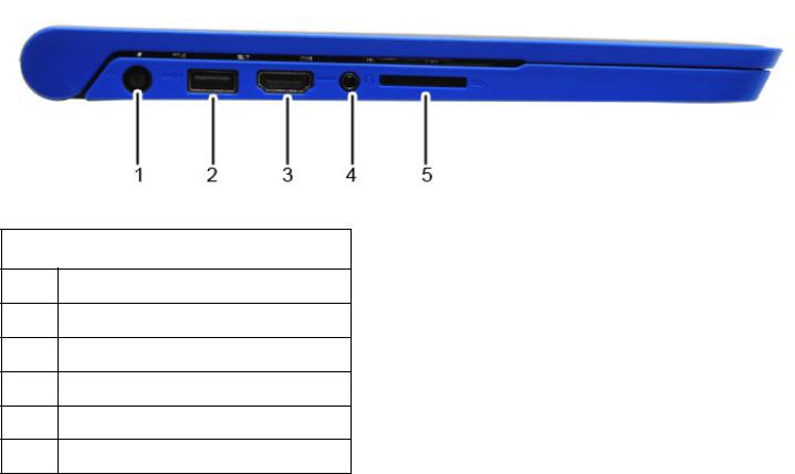
Left View
The Dell™ Chromebook™ 11 (3120) system left view and features are as below:
Chassis Left View Features and Locations
Label Description
1DC-in Jack
2USB 3.0 with BC (Battery Charging) 1.2
3HDMI
4 Audio in Jack
5SD Card Reader
1/1

Right View
The Dell™ Chromebook™ 11 (3120) system right view and features are as below:
Chassis Right View Features and Locations
Label Description
1Battery LED
2SIM Card Slot
3USB 2.0
4K-Lock Slot
1/1

Bottom View
The Dell™ Chromebook™ 11 (3120) system bottom view and features are as below:
Chassis Bottom View Features and Locations
Label Description
1 Express Service Code
2Service Tag
1/1

Chassis LED
This page contains all the information about LEDs on Dell™ Chromebook™ 11 (3120).
Battery LED
The battery status LED light is located at the right side of the chassis, as shown in the image below.
|
Battery Status LED |
|
|
LED Light Status |
Description |
|
|
|
AC powered, charge level higher than 97% |
|
|
O |
Battery powered, charge level higher than 10% |
|
|
|
Battery powered, charge level less than 10%, machine in S5 state |
|
|
White |
AC powered, charge level less than 97%, charging |
|
|
Amber |
Battery powered, charge level less than 10%, machine in S0 or S3 state |
|
|
Blinking Amber |
Battery error |
|
|
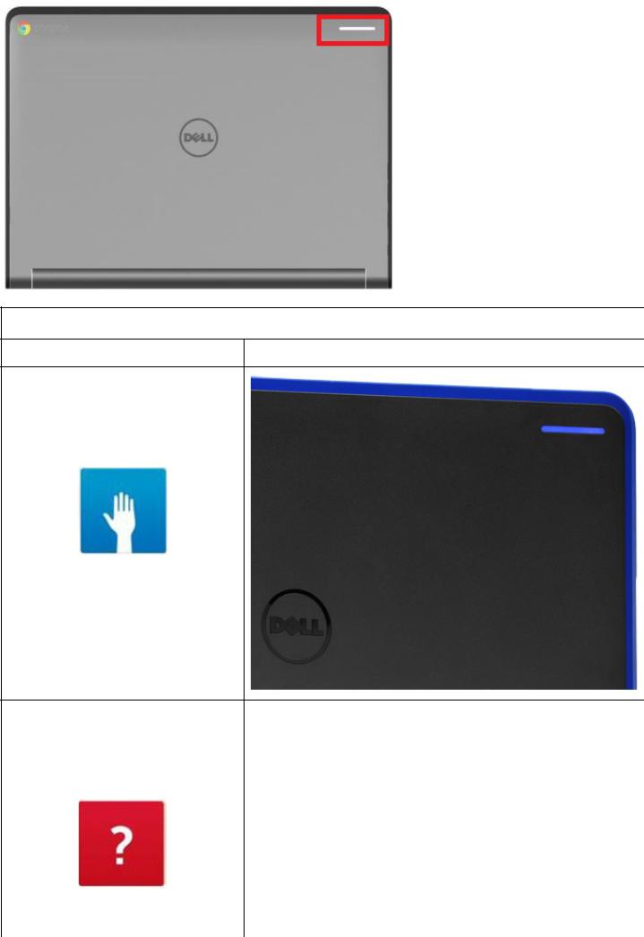
Dell Activity Light
Chromebook 11 (3120) comes with a 7 color Dell Activity light LEDs outside of the LCD back cover which can be use for interactivity between students and teachers.
For more information about Dell Activity Light, please visit Dell Bright Light in the software section. Location of the Dell Activity Light as highlighted in the image below.
1/4
Dell Activity Light
LED Light Status |
Chassis LED Light |
Blue
Red
2/4
Yellow
Others
Webcam LED
3/4
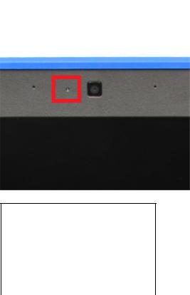
Chromebook 11 (3120) will have a webcam LED indicator on the LCD bezel, as shown in the image below.
Webcam Status LED
LED Light Status |
Description |
|
|
O |
Webcam o |
|
|
White |
Webcam on |
|
|
4/4
Field Service Information
This section covers field service information.
The information in this section is specifically for field service personnel who perform installation, diagnosis, and repair activities. Field personnel are required to know the issues and procedures in this document whether or not they perform all the service tasks.
Information in this section is required knowledge, but should never override regional or local policies and procedures
The sections and primary pages in this document are as follows:
 Safety Precautions — Generic safety precautions for every service event.
 Tools & Utilities — Hand tools needed to service the Dell™ Chromebook™ 11 (3120).
 Need to Know — Information and instructions for the Chromebook that requires additional attention. This section may contain critical call outs, New, Unique, Di erent and Di cult (NUDDs), and common error codes.
 Diagnostic — Available diagnostic tools for the Chromebook 11 (3120).
 Disassembly and Reassembly — Instructions for removing each replaceable part, with information needed before, during, and after parts replacement.
 RMA Shim — Information and instructions which must be done whenever a hardware replacement takes place.
1/1
Safety Precautions
Observe the following safety precautions when you perform any installation or break/fix procedures involving disassembly or reassembly:
 Turn o the system and all attached peripherals.
 Disconnect the system and all attached peripherals from AC power, and then remove the battery.
 Disconnect all network cables, telephone or telecommunications lines from the system.
 Use a wrist grounding strap and mat when working inside any computer system to avoid electrostatic discharge (ESD) damage.
 After removing a system component, carefully place the removed component on an anti-static mat.
  Wear shoes with non-conductive rubber soles to help reduce the risk of being shocked or seriously injured in an electrical accident.
Standby Power
Dell products with standby power must be completely unplugged before the case is opened. Systems that incorporate standby power are essentially powered while turned o . The internal power enables the system to be remotely turned on (wake on LAN), suspended into a sleep mode, and have other advanced power management features.
After you unplug a system and before you remove components, wait approximately 30 to 45 seconds to allow the charge to drain from the circuits. Remove the battery from portable computers.
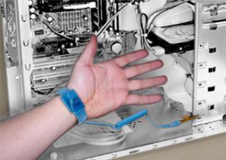
Bonding
Bonding is a method for connecting two or more grounding conductors to the same electrical potential. This is done through the use of a Field Service ESD kit. When connecting a bonding wire, always ensure that it is connected to bare metal and never to a painted or non-metal surface. The wrist strap should be secure and in full contact with your skin, and be sure to always remove all jewelry such as watches, bracelets, or rings prior to bonding yourself and the equipment.
Bonding Properly
Electrostatic Discharge Protection
ESD is a major concern when you handle electronic components, especially sensitive components such as expansion cards, processors, memory DIMMs, and system boards. Very slight charges can damage circuits in ways that may not be obvious, such as intermittent problems or a shortened product life span. As the industry pushes for lower power requirements and increased density, ESD protection is an increasing
1/7
concern.
Due to the increased density of semiconductors used in recent Dell products, the sensitivity to static damage is now higher than in earlier Dell products. For this reason some previously approved methods of handling parts are no longer applicable.
There are two recognized types of ESD damage: catastrophic and intermittent failures.
 Catastrophic —The damage causes an immediate and complete loss of device functionality. An example of catastrophic failure is a memory DIMM that has received a static shock and immediately generates a "No POST/No Video" symptom with a beep code emitted for missing or nonfunctional memory.
NOTE: Catastrophic failures represent approximately 20 percent of ESD-related failures.
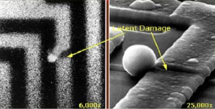
 Intermittent —The DIMM receives a static shock, but the tracing is merely weakened and does not immediately produce outward symptoms related to the damage. The weakened trace may take weeks or months to melt, and in the meantime may cause degradation of memory integrity, intermittent memory errors, etc.
NOTE: Intermittent failures represent approximately 80 percent of ESD-related failures. The high rate of intermittent failures means that most of the time when damage occurs, it is not immediately recognizable.
The more di cult type of damage to recognize and troubleshoot is the intermittent (also called latent or “walking wounded”) failure. The following image shows an example of intermittent damage to a memory DIMM trace. Although the damage is done, the symptoms may not become an issue or cause permanent failure symptoms for some time after the damage occurs.
Intermittent (Latent) Damage to a Wiring Trace
Do the following to prevent ESD damage:
 Use a wired ESD wrist strap that is properly grounded.
The use of wireless anti-static straps is no longer allowed; they do not provide adequate protection.
Touching the chassis before handling parts does not ensure adequate ESD protection on parts with increased sensitivity to ESD damage.
Chassis "Bare Metal" Grounding (Unacceptable)
2/7

 Handle all static-sensitive components in a static-safe area. If possible, use anti-static floor pads and workbench pads.
 When handling static-sensitive components, grasp them by the sides, not the top. Avoid touching pins and circuit boards.
 When unpacking a static-sensitive component from its shipping carton, do not remove the component from the anti-static packing material until you are ready to install the component. Before unwrapping the anti-static packaging, be sure to discharge static electricity from your body.
 Before transporting a static-sensitive component, place it in an anti-static container or packaging.
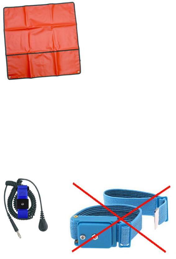
The ESD Field Service Kit
The unmonitored Field Service kit is the most commonly used. Each Field Service kit includes three main components: anti-static mat, wrist strap, and bonding wire.
ESD Field Service Kit
AntiStatic Mat
The anti-static mat is dissipative and should be used to safely place parts on during service procedures. When using an anti-static mat, your wrist strap should be snug and the bonding wire should be connected to the mat and to bare-metal on the system being worked on. Once deployed properly, service parts can be removed from the ESD bag and placed directly on the mat. Remember, the only safe place for ESDsensitive items are in your hand, on the ESD mat, in the system, or inside a bag.
3/7
Anti-Static Mat
Wrist Strap and Bonding Wire
The wrist strap and bonding wire can be either directly connected between your wrist and bare metal on the hardware if the ESD mat is not required, or connected to the anti-static mat to protect hardware that is temporarily placed on the mat. The physical connection of the wrist strap and bonding wire between your skin, the ESD mat, and the hardware is known as bonding. Use only Field Service kits with a wrist strap, mat, and bonding wire. Never use wireless wrist straps.
Always be aware that the internal wires of a wrist strap are prone to damage from normal wear and tear, and must be checked regularly with a wrist strap tester in order to avoid accidental ESD hardware damage. It is recommended to test the wrist strap and bonding wire a minimum of once per week.
Wrist Strap and Bonding Wire Wireless ESD Strap (Unacceptable)
ESD Wrist Strap Tester
4/7
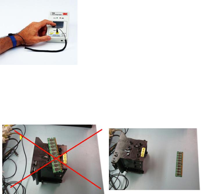
The wires inside of an ESD strap are prone to damage over time. When using an unmonitored kit, it is best practice to regularly test the strap prior to each service call, and at a minimum, test once per week. A wrist
strap tester is the best method for doing this test. If you do not have your own wrist strap tester, check with your regional o ce to find out if they have one. To perform the test, plug the wrist-strap’s bondingwire into the tester while it is strapped to your wrist and push the button to test. A green LED is lit if the test is successful; a red LED is lit and an alarm sounds if the test fails.
Wrist Strap Tester
Insulator Elements
It is critical to keep ESD sensitive devices, such as plastic heat sink casings, away from internal parts that are insulators and often highly charged.
Unacceptable — DIMM lying on an insulator part (plastic heat sink shroud)
Acceptable — DIMM separated from the insulator part
Consider the Working Environment
Before deploying the ESD Field Service kit, assess the situation at the customer location. For example, deploying the kit for a server environment is di erent than for a desktop or portable environment. Servers are typically installed in a rack within a data center; desktops or portables are typically placed on o ce desks or cubicles.
Always look for a large open flat work area that is free of clutter and large enough to deploy the ESD kit with additional space to accommodate the type of system that is being repaired. The workspace should
5/7
also be free of insulators that can cause an ESD event. On the work area, insulators such as Styrofoam and other plastics should always be moved at least 12 inches or 30 centimeters away from sensitive parts before physically handling any hardware components.
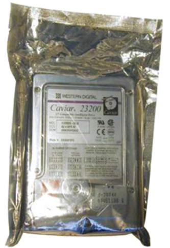
ESD Packaging
All ESD-sensitive devices must be shipped and received in static-safe packaging. Metal, static-shielded bags are preferred. However, you should always return the damaged part using the same ESD bag and packaging that the new part arrived in. The ESD bag should be folded over and taped shut and all the same foam packing material should be used in the original box that the new part arrived in.
ESD-sensitive devices should be removed from packaging only at an ESD-protected work surface, and parts should never be placed on top of the ESD bag because only the inside of the bag is shielded. Always place parts in your hand, on the ESD mat, in the system, or inside an anti-static bag.
ESD Packaging
Transporting Sensitive Components
When transporting ESD-sensitive components such as replacement parts or parts to be returned to Dell, it is critical to place these parts in anti-static bags for safe transport.
ESD Protection Summary
It is strongly suggested that all field service engineers use the traditional wired ESD grounding wrist strap and protective anti-static mat at all times when servicing Dell products. In addition, it is critical that engineers keep sensitive parts separate from all insulator parts while performing service and that they use
6/7
anti-static bags for transporting sensitive components.
Lifting Equipment
WARNING: Do not lift greater than 50 pounds. Always obtain assistance from another person or persons, or use a mechanical lifting device.
Adhere to the following guidelines when lifting equipment:
1.Get a firm balanced footing. Keep your feet apart for a stable base, and point your toes out.
2.Bend your knees. Do not bend at the waist.
3.Tighten stomach muscles. Abdominal muscles support your spine when you lift, o setting the force of the load.
4.Lift with your legs, not your back.
5.Keep the load close. The closer it is to your spine, the less force it exerts on your back.
6.Keep your back upright, whether lifting or setting down the load. Do not add the weight of your body to the load. Avoid twisting your body and back.
7.Follow the same techniques in reverse to set the load down.
7/7
Tools Required
A set of required and optional tools are necessary to service the product.
1.Small Phillips-head screwdriver, size #1
2.Small Phillips-head screwdriver, size #1
3.Plastic scribe
4.Small flat-head screwdriver
5.Tork 5 screwdriver
1/1
Disassembly and Reassembly
This section covers all the disassembly and reassembly of the Dell™ Chromebook™ 11 (3120).
1/1

Sim Card Disassembly
Sim Card Disassembly Video
PREREQUISITES
Pre-removal parts: 1. None
Sim Card |
Establishing image. |
1/5
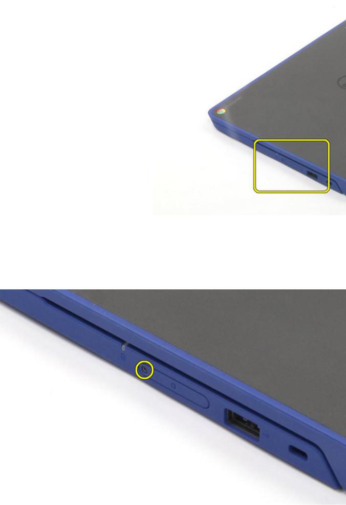
Sim Card Disassembly
1. Remove the T5 screw.
2. Remove the cover.
2/5

3. Use the push pin to eject the sim card.
4. Remove the sim card.
3/5

The removal is complete.
Sim Card Reassembly
1.Insert the sim card.
2.Close the cover.
4/5
3. Tighten the T5 screw.
5/5
 Loading...