


 Loading...
Dell™ PowerConnect™ 35xx Systems
User’s Guide
w w w . d e l l . c o m | s u p p o r t . d e l l . c o m

Notes, Cautions, and Warnings
NOTE: A NOTE indicates important information that helps you make better use of your computer.
CAUTION: A CAUTION indicates potential damage to hardware or loss of data if instructions are not followed.
WARNING: A WARNING indicates a potential for property damage, personal injury, or death.
____________________
Information in this document is subject to change without notice. © 2007–2008 Dell Inc. All rights reserved.
Reproduction of these materials in any manner whatsoever without the written permission of Dell Inc. is strictly forbidden.
Trademarks used in this text: Dell, the DELL logo, Dell OpenManage, and PowerConnect are trademarks of Dell Inc. Microsoft and Windows are either trademarks or registered trademarks of Microsoft Corporation in the United States and/or other countries.
Other trademarks and trade names may be used in this document to refer to either the entities claiming the marks and names or their products. Dell Inc. disclaims any proprietary interest in trademarks and trade names other than its own.
December 2008 |
Rev. A01 |

Contents
1 Introduction . . . . . . . . . . . . . . . . . . . . . . . . . . . . . . . . . |
11 |
System Description. . . . . . . . . . . . . . . . . . . . . . . . . . . . . . . . |
11 |
PowerConnect 3524. . . . . . . . . . . . . . . . . . . . . . . . . . . . . |
11 |
PowerConnect 3524P . . . . . . . . . . . . . . . . . . . . . . . . . . . . |
11 |
PowerConnect 3548. . . . . . . . . . . . . . . . . . . . . . . . . . . . . |
12 |
PowerConnect 3548P . . . . . . . . . . . . . . . . . . . . . . . . . . . . |
12 |
Stacking Overview. . . . . . . . . . . . . . . . . . . . . . . . . . . . . . . . |
12 |
Understanding the Stack Topology . . . . . . . . . . . . . . . . . . . . . |
13 |
Stacking Failover Topology . . . . . . . . . . . . . . . . . . . . . . . . . |
13 |
Stacking Members and Unit ID . . . . . . . . . . . . . . . . . . . . . . . |
13 |
Removing and Replacing Stacking Members . . . . . . . . . . . . . . . |
14 |
Exchanging Stacking Members . . . . . . . . . . . . . . . . . . . . . . |
15 |
Switching from the Stack Master to the Backup Stack Master . . . . . . |
17 |
Features Overview . . . . . . . . . . . . . . . . . . . . . . . . . . . . . . . . |
17 |
IP Version 6 (IPv6) Support . . . . . . . . . . . . . . . . . . . . . . . . . |
17 |
Power over Ethernet . . . . . . . . . . . . . . . . . . . . . . . . . . . . |
17 |
Head of Line Blocking Prevention . . . . . . . . . . . . . . . . . . . . . |
18 |
Flow Control Support (IEEE 802.3X) . . . . . . . . . . . . . . . . . . . . . |
18 |
Back Pressure Support . . . . . . . . . . . . . . . . . . . . . . . . . . . |
18 |
Virtual Cable Testing (VCT) . . . . . . . . . . . . . . . . . . . . . . . . . |
18 |
MDI/MDIX Support . . . . . . . . . . . . . . . . . . . . . . . . . . . . . |
18 |
Auto Negotiation . . . . . . . . . . . . . . . . . . . . . . . . . . . . . . |
18 |
MAC Address Supported Features . . . . . . . . . . . . . . . . . . . . . |
19 |
Layer 2 Features . . . . . . . . . . . . . . . . . . . . . . . . . . . . . . |
20 |
VLAN Supported Features . . . . . . . . . . . . . . . . . . . . . . . . . |
21 |
Spanning Tree Protocol Features. . . . . . . . . . . . . . . . . . . . . . |
21 |
Link Aggregation . . . . . . . . . . . . . . . . . . . . . . . . . . . . . . |
22 |
Quality of Service Features . . . . . . . . . . . . . . . . . . . . . . . . . |
23 |
Device Management Features . . . . . . . . . . . . . . . . . . . . . . . |
23 |
Security Features . . . . . . . . . . . . . . . . . . . . . . . . . . . . . . |
25 |
Additional CLI Documentation . . . . . . . . . . . . . . . . . . . . . . . . . . |
26 |
Contents 3

2 Hardware Description . . . . . . . . . . . . . . . . . . . . . . . . . . |
27 |
Port Description . . . . . . . . . . . . . . . . . . . . . . . . . . . . . . . . . |
27 |
PowerConnect 3524 Port Description . . . . . . . . . . . . . . . . . . . |
27 |
The back panel contains an RPS connector, console port, |
|
and power connector.. . . . . . . . . . . . . . . . . . . . . . . . . . . . |
28 |
PowerConnect 3548 Port Description . . . . . . . . . . . . . . . . . . . |
28 |
SFP Ports . . . . . . . . . . . . . . . . . . . . . . . . . . . . . . . . . . |
29 |
RS-232 Console Port . . . . . . . . . . . . . . . . . . . . . . . . . . . . |
29 |
Physical Dimensions . . . . . . . . . . . . . . . . . . . . . . . . . . . . . . . |
30 |
LED Definitions . . . . . . . . . . . . . . . . . . . . . . . . . . . . . . . . . . |
30 |
Gigabit Port LEDs . . . . . . . . . . . . . . . . . . . . . . . . . . . . . . |
32 |
System LEDs . . . . . . . . . . . . . . . . . . . . . . . . . . . . . . . . |
33 |
Power Supplies . . . . . . . . . . . . . . . . . . . . . . . . . . . . . . . |
35 |
Stack ID Button . . . . . . . . . . . . . . . . . . . . . . . . . . . . . . . |
36 |
Reset Button . . . . . . . . . . . . . . . . . . . . . . . . . . . . . . . . |
37 |
Ventilation System . . . . . . . . . . . . . . . . . . . . . . . . . . . . . |
37 |
3Installing the PowerConnect 3524/P and
PowerConnect 3548/P . . . . . . . . . . . . . . . . . . . . . . . . . . 39
Site Preparation . . . . . . . . . . . . . . . . . . . . . . . . . . . . . . . . . |
39 |
Unpacking . . . . . . . . . . . . . . . . . . . . . . . . . . . . . . . . . . . . |
39 |
Package Contents. . . . . . . . . . . . . . . . . . . . . . . . . . . . . . |
39 |
Unpacking the Device . . . . . . . . . . . . . . . . . . . . . . . . . . . |
40 |
Mounting the Device. . . . . . . . . . . . . . . . . . . . . . . . . . . . . . . |
40 |
Installing in a Rack . . . . . . . . . . . . . . . . . . . . . . . . . . . . . |
40 |
Installing on a Flat Surface . . . . . . . . . . . . . . . . . . . . . . . . . |
41 |
Installing the Device on a Wall . . . . . . . . . . . . . . . . . . . . . . . |
42 |
Connecting to a Terminal . . . . . . . . . . . . . . . . . . . . . . . . . . |
43 |
Connecting a Device to a Power Supply . . . . . . . . . . . . . . . . . . . . |
43 |
Installing a Stack . . . . . . . . . . . . . . . . . . . . . . . . . . . . . . . . |
44 |
Overview . . . . . . . . . . . . . . . . . . . . . . . . . . . . . . . . . . |
44 |
Stacking PowerConnect 35xx Series Systems Switches. . . . . . . . . . |
44 |
Unit ID Selection Process. . . . . . . . . . . . . . . . . . . . . . . . . . |
46 |
Starting and Configuring the Device . . . . . . . . . . . . . . . . . . . . . . |
47 |
Connecting to the Device . . . . . . . . . . . . . . . . . . . . . . . . . . |
47 |
4 Contents

4 |
Configuring PowerConnect 3524/P and 3548/P . . . . . . . . . |
49 |
|
Configuration Procedures . . . . . . . . . . . . . . . . . . . . . . . . . . . . |
49 |
|
Booting the Switch . . . . . . . . . . . . . . . . . . . . . . . . . . . . . |
50 |
|
Initial Configuration . . . . . . . . . . . . . . . . . . . . . . . . . . . . . |
50 |
|
Advanced Configuration . . . . . . . . . . . . . . . . . . . . . . . . . . . . . |
54 |
|
Retrieving an IP Address From a DHCP Server. . . . . . . . . . . . . . . |
54 |
|
Receiving an IP Address From a BOOTP Server . . . . . . . . . . . . . . |
56 |
|
Security Management and Password Configuration. . . . . . . . . . . . |
56 |
|
Configuring Login Banners . . . . . . . . . . . . . . . . . . . . . . . . . . . |
59 |
|
Startup Procedures . . . . . . . . . . . . . . . . . . . . . . . . . . . . . . . |
59 |
|
Startup Menu Procedures . . . . . . . . . . . . . . . . . . . . . . . . . |
59 |
|
Software Download Through TFTP Server . . . . . . . . . . . . . . . . . |
63 |
|
Port Default Settings . . . . . . . . . . . . . . . . . . . . . . . . . . . . . . . |
65 |
|
Auto-Negotiation . . . . . . . . . . . . . . . . . . . . . . . . . . . . . . |
66 |
|
MDI/MDIX. . . . . . . . . . . . . . . . . . . . . . . . . . . . . . . . . . |
66 |
|
Flow Control. . . . . . . . . . . . . . . . . . . . . . . . . . . . . . . . . |
66 |
|
Back Pressure . . . . . . . . . . . . . . . . . . . . . . . . . . . . . . . |
66 |
|
Switching Port Default Settings . . . . . . . . . . . . . . . . . . . . . . |
67 |
5 |
Using Dell OpenManage Switch Administrator . . . . . . . . . |
69 |
|
Starting the Application . . . . . . . . . . . . . . . . . . . . . . . . . . . . . |
69 |
|
Understanding the Interface . . . . . . . . . . . . . . . . . . . . . . . . . . . |
69 |
|
Device Representation . . . . . . . . . . . . . . . . . . . . . . . . . . . |
71 |
|
Using the Switch Administrator Buttons . . . . . . . . . . . . . . . . . . . . |
72 |
|
Information Buttons. . . . . . . . . . . . . . . . . . . . . . . . . . . . . |
72 |
|
Device Management Buttons. . . . . . . . . . . . . . . . . . . . . . . . |
72 |
|
Field Definitions . . . . . . . . . . . . . . . . . . . . . . . . . . . . . . . . . |
73 |
|
Accessing the Device Through the CLI . . . . . . . . . . . . . . . . . . . . . |
73 |
|
Terminal Connection . . . . . . . . . . . . . . . . . . . . . . . . . . . . |
73 |
|
Telnet Connection. . . . . . . . . . . . . . . . . . . . . . . . . . . . . . |
74 |
Contents 5

Using the CLI . . . . . . . . . . . . . . . . . . . . . . . . . . . . . . . . . . . |
74 |
Command Mode Overview . . . . . . . . . . . . . . . . . . . . . . . . . |
74 |
User EXEC Mode . . . . . . . . . . . . . . . . . . . . . . . . . . . . . . |
75 |
Privileged EXEC Mode . . . . . . . . . . . . . . . . . . . . . . . . . . . |
75 |
Global Configuration Mode . . . . . . . . . . . . . . . . . . . . . . . . . |
76 |
6 Configuring System Information . . . . . . . . . . . . . . . . . . . |
77 |
Defining General Switch Information . . . . . . . . . . . . . . . . . . . . . . |
78 |
Viewing Switch Asset Information . . . . . . . . . . . . . . . . . . . . . |
78 |
Asset . . . . . . . . . . . . . . . . . . . . . . . . . . . . . . . . . . . . |
78 |
Defining System Time Settings . . . . . . . . . . . . . . . . . . . . . . . |
84 |
Viewing System Health Information . . . . . . . . . . . . . . . . . . . . |
90 |
Managing Power over Ethernet . . . . . . . . . . . . . . . . . . . . . . |
92 |
Viewing Version Information . . . . . . . . . . . . . . . . . . . . . . . . |
98 |
Managing Stack Members . . . . . . . . . . . . . . . . . . . . . . . . . |
99 |
Resetting the Device . . . . . . . . . . . . . . . . . . . . . . . . . . . |
100 |
Configuring SNTP Settings . . . . . . . . . . . . . . . . . . . . . . . . . . |
101 |
Defining SNTP Global Settings . . . . . . . . . . . . . . . . . . . . . . |
103 |
Defining SNTP Authentication Methods . . . . . . . . . . . . . . . . . |
105 |
Defining SNTP Servers . . . . . . . . . . . . . . . . . . . . . . . . . . |
107 |
Defining SNTP Interfaces. . . . . . . . . . . . . . . . . . . . . . . . . |
111 |
Managing Logs . . . . . . . . . . . . . . . . . . . . . . . . . . . . . . . . . |
113 |
Defining Global Log Parameters . . . . . . . . . . . . . . . . . . . . . |
114 |
Viewing the RAM Log Table. . . . . . . . . . . . . . . . . . . . . . . . |
118 |
Viewing the Log File Table . . . . . . . . . . . . . . . . . . . . . . . . |
120 |
Viewing the Device Login History. . . . . . . . . . . . . . . . . . . . . |
121 |
Modifying Remote Log Server Definitions . . . . . . . . . . . . . . . . |
123 |
Defining IP Addressing . . . . . . . . . . . . . . . . . . . . . . . . . . . . |
128 |
Configuring the Internet Protocol Version 6 (IPv6) . . . . . . . . . . . . |
129 |
Defining IPv4 Default Gateways . . . . . . . . . . . . . . . . . . . . . |
129 |
Defining IPv4 Interfaces . . . . . . . . . . . . . . . . . . . . . . . . . |
131 |
Defining DHCP IPv4 Interface Parameters . . . . . . . . . . . . . . . . |
134 |
Defining IPv6 Interfaces . . . . . . . . . . . . . . . . . . . . . . . . . |
137 |
Defining IPv6 Default Gateway . . . . . . . . . . . . . . . . . . . . . . |
142 |
Defining IPv6 ISATAP Tunnels . . . . . . . . . . . . . . . . . . . . . . |
145 |
Defining IPv6 Neighbors . . . . . . . . . . . . . . . . . . . . . . . . . |
148 |
Viewing the IPv6 Routes Table . . . . . . . . . . . . . . . . . . . . . . |
152 |
6 Contents

Configuring Domain Name Systems . . . . . . . . . . . . . . . . . . . |
154 |
Defining Default Domains. . . . . . . . . . . . . . . . . . . . . . . . . |
157 |
Mapping Domain Host . . . . . . . . . . . . . . . . . . . . . . . . . . |
159 |
Defining ARP Settings . . . . . . . . . . . . . . . . . . . . . . . . . . |
162 |
Running Cable Diagnostics . . . . . . . . . . . . . . . . . . . . . . . . . . |
165 |
Viewing Copper Cable Diagnostics . . . . . . . . . . . . . . . . . . . . |
165 |
Viewing Optical Transceiver Diagnostics . . . . . . . . . . . . . . . . |
167 |
Managing Management Security . . . . . . . . . . . . . . . . . . . . . . . |
170 |
Defining Access Profiles . . . . . . . . . . . . . . . . . . . . . . . . . |
170 |
Defining Authentication Profiles . . . . . . . . . . . . . . . . . . . . . |
177 |
Selecting Authentication Profiles . . . . . . . . . . . . . . . . . . . . |
181 |
Managing Passwords. . . . . . . . . . . . . . . . . . . . . . . . . . . |
184 |
Displaying Active Users . . . . . . . . . . . . . . . . . . . . . . . . . |
187 |
Defining the Local User Databases. . . . . . . . . . . . . . . . . . . . |
189 |
Defining Line Passwords . . . . . . . . . . . . . . . . . . . . . . . . . |
192 |
Defining Enable Passwords. . . . . . . . . . . . . . . . . . . . . . . . |
194 |
Defining TACACS+ Settings. . . . . . . . . . . . . . . . . . . . . . . . |
196 |
Configuring RADIUS Settings . . . . . . . . . . . . . . . . . . . . . . . |
200 |
Configuring LLDP and MED . . . . . . . . . . . . . . . . . . . . . . . . . . |
205 |
Defining LLDP Properties . . . . . . . . . . . . . . . . . . . . . . . . . |
207 |
Configuring LLDP Using CLI Commands . . . . . . . . . . . . . . . . . |
208 |
Defining LLDP Port Settings . . . . . . . . . . . . . . . . . . . . . . . |
208 |
Defining LLDP MED Network Policy . . . . . . . . . . . . . . . . . . . |
211 |
Defining LLDP MED Port Settings . . . . . . . . . . . . . . . . . . . . |
213 |
Viewing the LLDP Neighbors Information . . . . . . . . . . . . . . . . |
217 |
Defining SNMP Parameters . . . . . . . . . . . . . . . . . . . . . . . . . . |
219 |
Defining SNMP Global Parameters. . . . . . . . . . . . . . . . . . . . |
220 |
Defining SNMP View Settings . . . . . . . . . . . . . . . . . . . . . . |
223 |
Defining SNMP Access Control . . . . . . . . . . . . . . . . . . . . . |
227 |
Assigning SNMP User Security . . . . . . . . . . . . . . . . . . . . . |
230 |
Defining SNMP Communities . . . . . . . . . . . . . . . . . . . . . . . |
234 |
Defining SNMP Notification Filters . . . . . . . . . . . . . . . . . . . . |
238 |
Defining SNMP Notification Recipients . . . . . . . . . . . . . . . . . |
240 |
Managing Files. . . . . . . . . . . . . . . . . . . . . . . . . . . . . . . . . |
246 |
Downloading Files . . . . . . . . . . . . . . . . . . . . . . . . . . . . |
247 |
Uploading Files . . . . . . . . . . . . . . . . . . . . . . . . . . . . . . |
250 |
Activating Image Files . . . . . . . . . . . . . . . . . . . . . . . . . . |
253 |
Contents 7

Copying Files . . . . . . . . . . . . . . . . . . . . . . . . . . . . . . . |
255 |
Managing Device Files . . . . . . . . . . . . . . . . . . . . . . . . . . |
257 |
Configuring Advanced Settings . . . . . . . . . . . . . . . . . . . . . . . . |
259 |
Configuring General Settings . . . . . . . . . . . . . . . . . . . . . . . |
259 |
7 Configuring Switch Information. . . . . . . . . . . . . . . . . . . |
261 |
Configuring Network Security . . . . . . . . . . . . . . . . . . . . . . . . . |
261 |
Port Based Authentication . . . . . . . . . . . . . . . . . . . . . . . . |
262 |
Configuring Advanced Port Based Authentication . . . . . . . . . . . . |
268 |
Authenticating Users . . . . . . . . . . . . . . . . . . . . . . . . . . . |
271 |
Configuring Port Security . . . . . . . . . . . . . . . . . . . . . . . . . |
273 |
ACL Overview . . . . . . . . . . . . . . . . . . . . . . . . . . . . . . . . . |
276 |
Defining IP based ACLs . . . . . . . . . . . . . . . . . . . . . . . . . . |
277 |
Defining MAC Based Access Control Lists . . . . . . . . . . . . . . . . |
283 |
Defining ACL Binding . . . . . . . . . . . . . . . . . . . . . . . . . . . |
286 |
Configuring DHCP Snooping . . . . . . . . . . . . . . . . . . . . . . . . . . |
288 |
Defining DHCP Snooping Global Parameters. . . . . . . . . . . . . . . |
289 |
Defining DHCP Snooping on VLANs . . . . . . . . . . . . . . . . . . . |
291 |
Defining Trusted Interfaces. . . . . . . . . . . . . . . . . . . . . . . . |
292 |
Adding Interfaces to the DHCP Snooping Database . . . . . . . . . . . |
294 |
Configuring Ports. . . . . . . . . . . . . . . . . . . . . . . . . . . . . . . . |
297 |
Defining Port Configuration . . . . . . . . . . . . . . . . . . . . . . . . |
297 |
Defining LAG Parameters . . . . . . . . . . . . . . . . . . . . . . . . . |
304 |
Enabling Storm Control . . . . . . . . . . . . . . . . . . . . . . . . . . |
308 |
Defining Port Mirroring Sessions . . . . . . . . . . . . . . . . . . . . . |
312 |
Configuring Address Tables . . . . . . . . . . . . . . . . . . . . . . . . . . |
315 |
Defining Static Addresses . . . . . . . . . . . . . . . . . . . . . . . . |
315 |
Viewing Dynamic Addresses . . . . . . . . . . . . . . . . . . . . . . . |
318 |
Configuring GARP . . . . . . . . . . . . . . . . . . . . . . . . . . . . . . . |
321 |
Defining GARP Timers . . . . . . . . . . . . . . . . . . . . . . . . . . |
322 |
Configuring the Spanning Tree Protocol . . . . . . . . . . . . . . . . . . . |
325 |
Defining STP Global Settings . . . . . . . . . . . . . . . . . . . . . . . |
325 |
Defining STP Port Settings . . . . . . . . . . . . . . . . . . . . . . . . |
331 |
Defining STP LAG Settings . . . . . . . . . . . . . . . . . . . . . . . . |
336 |
Defining Rapid Spanning Tree . . . . . . . . . . . . . . . . . . . . . . |
339 |
8 Contents

Configuring Multiple Spanning Tree . . . . . . . . . . . . . . . . . . . |
343 |
Defining MSTP Interface Settings . . . . . . . . . . . . . . . . . . . . |
347 |
Configuring VLANs . . . . . . . . . . . . . . . . . . . . . . . . . . . . . . . |
351 |
Defining VLAN Membership . . . . . . . . . . . . . . . . . . . . . . . |
352 |
Defining VLAN Ports Settings. . . . . . . . . . . . . . . . . . . . . . . |
357 |
Defining VLAN LAGs Settings. . . . . . . . . . . . . . . . . . . . . . . |
359 |
Binding MAC Address to VLANs . . . . . . . . . . . . . . . . . . . . . |
362 |
Defining VLAN Protocol Groups . . . . . . . . . . . . . . . . . . . . . |
364 |
Adding Interfaces to Protocol Groups . . . . . . . . . . . . . . . . . . |
367 |
Configuring GVRP Parameters . . . . . . . . . . . . . . . . . . . . . . |
369 |
Configuring Voice VLAN . . . . . . . . . . . . . . . . . . . . . . . . . . . . |
374 |
Defining Voice VLAN Global Parameters . . . . . . . . . . . . . . . . . |
374 |
Defining Voice VLAN Port Settings . . . . . . . . . . . . . . . . . . . . |
377 |
Defining OUIs . . . . . . . . . . . . . . . . . . . . . . . . . . . . . . . |
379 |
Aggregating Ports . . . . . . . . . . . . . . . . . . . . . . . . . . . . . . . |
382 |
Defining LACP Parameters . . . . . . . . . . . . . . . . . . . . . . . . |
383 |
Defining LAG Membership . . . . . . . . . . . . . . . . . . . . . . . . |
385 |
Multicast Forwarding Support. . . . . . . . . . . . . . . . . . . . . . . . . |
387 |
Defining Multicast Global Parameters . . . . . . . . . . . . . . . . . . |
387 |
Adding Bridge Multicast Address Members . . . . . . . . . . . . . . . |
389 |
Assigning Multicast Forward All Parameters . . . . . . . . . . . . . . |
394 |
IGMP Snooping . . . . . . . . . . . . . . . . . . . . . . . . . . . . . . |
396 |
Unregistered Multicast . . . . . . . . . . . . . . . . . . . . . . . . . . |
401 |
8 Viewing Statistics . . . . . . . . . . . . . . . . . . . . . . . . . . . . |
405 |
Viewing Tables . . . . . . . . . . . . . . . . . . . . . . . . . . . . . . . . . |
405 |
Viewing Utilization Summary . . . . . . . . . . . . . . . . . . . . . . . |
405 |
Viewing Counter Summary . . . . . . . . . . . . . . . . . . . . . . . . |
407 |
Viewing Interface Statistics . . . . . . . . . . . . . . . . . . . . . . . |
408 |
Viewing Etherlike Statistics. . . . . . . . . . . . . . . . . . . . . . . . |
411 |
Viewing GVRP Statistics . . . . . . . . . . . . . . . . . . . . . . . . . |
414 |
Viewing EAP Statistics . . . . . . . . . . . . . . . . . . . . . . . . . . |
418 |
Viewing EAP Statistics Using the CLI Commands . . . . . . . . . . . . |
419 |
Viewing RMON Statistics . . . . . . . . . . . . . . . . . . . . . . . . . . . |
420 |
Viewing RMON Statistics Group . . . . . . . . . . . . . . . . . . . . . |
420 |
Viewing RMON History Control Statistics . . . . . . . . . . . . . . . . |
423 |
Contents 9

Viewing the RMON History Table . . . . . . . . . . . . . . . . . . . . . |
425 |
Defining Device RMON Events . . . . . . . . . . . . . . . . . . . . . . |
428 |
Viewing the RMON Events Log . . . . . . . . . . . . . . . . . . . . . . |
430 |
Defining RMON Device Alarms . . . . . . . . . . . . . . . . . . . . . . |
431 |
Viewing Charts . . . . . . . . . . . . . . . . . . . . . . . . . . . . . . . . . |
435 |
Viewing Port Statistics . . . . . . . . . . . . . . . . . . . . . . . . . . |
436 |
Viewing LAG Statistics . . . . . . . . . . . . . . . . . . . . . . . . . . |
437 |
Viewing the CPU Utilization . . . . . . . . . . . . . . . . . . . . . . . . |
438 |
Viewing CPU Utilization Using CLI Commands . . . . . . . . . . . . . . |
440 |
9 |
Configuring Quality of Service. . . . . . . . . . . . . . . . . . . . |
441 |
|
Quality of Service (QoS) Overview . . . . . . . . . . . . . . . . . . . . . . |
441 |
|
CoS Services . . . . . . . . . . . . . . . . . . . . . . . . . . . . . . . |
442 |
|
Configuring QoS Global Settings . . . . . . . . . . . . . . . . . . . . . . . |
443 |
|
Defining QoS Interface Settings . . . . . . . . . . . . . . . . . . . . . |
445 |
|
Defining Bandwidth Settings . . . . . . . . . . . . . . . . . . . . . . . |
446 |
|
Mapping CoS Values to Queues . . . . . . . . . . . . . . . . . . . . . |
448 |
|
Mapping DSCP Values to Queues . . . . . . . . . . . . . . . . . . . . |
450 |
10 |
Glossary . . . . . . . . . . . . . . . . . . . . . . . . . . . . . . . . . . . |
453 |
A |
Device Feature Interaction Information . . . . . . . . . . . . . |
467 |
Index . . . . . . . . . . . . . . . . . . . . . . . . . . . . . . . . . . . . . . . . |
471 |
|
10 Contents
Introduction
Dell™ PowerConnect™ 3524/3548 and PowerConnect 3524P/3548P are stackable, advanced multi-layer devices. PowerConnect units can function either as stand-alone, multi-layer, switching devices or stackable devices with up to eight stacking members.
This User Guide contains the information needed for installing, configuring, and maintaining the device.
System Description
PowerConnect 3524/3548 and PowerConnect 3524P/3548P combine versatility with minimal management. The PowerConnect 3524 and 3548 series include the following device types:
•PowerConnect 3524
•PowerConnect 3524P
•PowerConnect 3548
•PowerConnect 3548P
PowerConnect 3524
The PowerConnect 3524 provides 24 10/100Mbps ports plus two SFP ports, and two Copper ports which can be used to forward traffic in a stand-alone device, or as stacking ports when the device is stacked. The device also provides one RS-232 console port. The PowerConnect 3524 is a stackable device, but also operates as a stand-alone device.
PowerConnect 3524P
The PowerConnect 3524P provides 24 10/100Mbps ports plus two SFP ports, and two Copper ports which can be used to forward traffic in a stand-alone device, or as stacking ports when the device is stacked. The device also provides one RS-232 console port. The PowerConnect 3524P is a stackable device, but also operates as a stand-alone device. The PowerConnect 3524P also provides Power over Ethernet (PoE).
Figure 1-1. PowerConnect 3524 and PowerConnect 3524P
Introduction 11
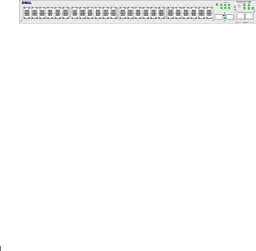
PowerConnect 3548
The PowerConnect 3548 provides 48 10/100Mbps ports plus two SFP ports, and two Copper ports which can be used to forward traffic in a stand-alone device, or as stacking ports when the device is stacked. The device also provides one RS-232 console port. The PowerConnect 3548 is a stackable device, but also functions as a stand-alone device.
PowerConnect 3548P
The PowerConnect 3548P provides 48 10/100Mbps ports, two SFP ports, and two copper ports that can be used to forward traffic when the device is in stand-alone mode, or as stacking ports when the device is part of a stack. The device also provides one RS-232 console port. In addition, PowerConnect 3548P provides PoE.
Figure 1-2. PowerConnect 3548 and PowerConnect 3548P
Stacking Overview
PowerConnect 3524/P and PowerConnect 3548/P stacking provides multiple switch management through a single point as if all stack members are a single unit. All stack members are accessed through a single IP address through which the stack is managed. The stack is managed from a:
•Web-based interface
•SNMP Management Station
•Command Line Interface (CLI)
PowerConnect 3524/P and PowerConnect 3548/P devices support stacking up to eight units per stack, or can operate as stand-alone units.
During the Stacking setup, one switch is selected as the Stack Master and another stacking member can be selected as the Backup Master. All other devices are selected as stack members, and assigned a unique Unit ID.
Switch software is downloaded separately for each stack members. However, all units in the stack must be running the same software version.
Switch stacking and configuration is maintained by the Stack Master. The Stack Master detects and reconfigures the ports with minimal operational impact in the event of:
•Unit Failure
•Inter-unit Stacking Link Failure
•Unit Insertion
•Removal of a Stacking Unit
12 Introduction

Understanding the Stack Topology
The PowerConnect 35xx series systems operates in a Ring topology. A stacked Ring topology is where all devices in the stack are connected to each other forming a circle. Each device in the stack accepts data and sends it to the device to which it is attached. The packet continues through the stack until it reaches its destination. The system discovers the optimal path on which to send traffic.
Figure 1-3. Stacking Ring Topology
Ring Topology
Most difficulties incurred in Ring topologies occur when a device in the ring becomes non-functional, or a link is severed. With the PowerConnect 3524/P and PowerConnect 3548/P stack, the system automatically switches to a Stacking Failover topology without any system downtime. An SNMP message is automatically generated, but no stack management action is required. However, the stacking link or stacking member must be repaired to ensure the stacking integrity.
After the stacking issues are resolved, the device can be reconnected to the stack without interruption, and the Ring topology is restored.
Stacking Failover Topology
If a failure occurs in the stacking topology, the stack reverts to Stacking Failover Topology. In the Stacking Failover topology, devices operate in a chain formation. The Stack Master determines where the packets are sent. Each unit is connected to two neighboring devices, except for the top and bottom units.
Stacking Members and Unit ID
Stacking Unit IDs are essential to the stacking configuration. The stacking operation is determined during the boot process. The operation mode is determined by the Unit ID selected during the initialization process. For example, if the user selected the stand-alone mode, the device boots in the boot-up process as a stand-alone device.
Introduction 13

The device units are shipped with a default Unit ID of the stand-alone unit. If the device is operating as a stand-alone unit, all stacking LEDs are off.
Once the user selects a different Unit ID, it is not erased, and remains valid, even if the unit is reset.
Unit ID 1 and Unit ID 2 are reserved for Master enabled units. Unit IDs 3 to 8 can be defined for stack members.
When the Master unit boots or when inserting or removing a stack member, the Master unit initiates a stacking discovering process.
NOTE: If two members are discovered with the same Unit ID the stack continues to function, however only the unit with the older join time joins the stack. A message is sent to the user, notifying that a unit failed to join the stack.
Removing and Replacing Stacking Members
Unit 1 and Unit 2 are Master enabled units. Unit 1 and Unit 2 are either designated as Master Unit or Backup Master Unit. The stack Master assignment is performed during the configuration process. One Master enabled stack member is elected as Master, and the other Master enabled stack member is elected as Backup Master, according to the following decision process:
•If only one Stack Master enabled unit is present, it is elected as the Master.
•If two Master enabled stacking members are present, and one has been manually configured as the Stack Master, the manually configured member is elected as Stack Master.
•If two Master enabled units are present and neither has been manually configured as the Master, the one with the longer up-time is elected as the Stack Master.
•If two Master enabled units are present and both have been manually configured as the Master, the one with the longer up-time is elected as the Stack Master.
•If the two Master enabled stacking members are the same age, Unit 1 is elected as the Stack Master.
NOTE: Two stacking member are considered the same age if they were inserted within a ten minute interval.
For example, Unit 2 is inserted in the first minute of a ten-minute cycle, and Unit 1 is inserted in fifth minute of the same cycle, the units are considered to be the same age. If there are two Master enabled stack members that are the same age, then Unit 1 is elected master.
The Stack Master and the Backup Master maintain a Warm Standby. The Warm Standby ensures that the Backup Master takes over for the Stack Master if a failover occurs. This guarantees that the stack continues to operate normally.
During the Warm Standby, the Master and the Backup Master are synchronized with the static configuration only. When the Stacking Master is configured, the Stack Master must synchronize the Stacking Backup Master. The Dynamic configuration is not saved, for example, dynamically learned MAC addresses are not saved.
14 Introduction

Each port in the stack has a specific Unit ID, port type, and port number, which are part of both the configuration commands and the configuration files. Configuration files are managed only from the device Stack Master, including:
•Saving to the FLASH
•Uploading Configuration files to an external TFTP Server/HTTP Client
•Downloading Configuration files from an external TFTP Server/HTTP Client
NOTE: Stack configuration for all configured ports is saved, even if the stack is reset and/or the ports are no longer present.
Whenever a reboot occurs, topology discovery is performed, and the Master learns all units in the stack. Unit IDs are saved in the unit and are learned through topology discovery. If a unit attempts to boot without a selected Master, and the unit is not operating in stand-alone mode, the unit does not boot.
Configuration files are changed only through explicit user configuration. Configuration files are not automatically modified when:
•Units are Added
•Units are Removed
•Units are reassigned Unit IDs
•Units toggle between Stacking Mode and Stand-alone Mode
Each time the system reboots, the Startup Configuration file in the Master unit is used to configure the stack.
If a stack member is removed from the stack, and then replaced with a unit with the same Unit ID, the stack member is configured with the original device configuration. Only ports which are physically present are displayed in the PowerConnect OpenManage Switch Administrator home page, and can be configured through the web management system. Non-present ports are configured through the CLI or SNMP interfaces.
Exchanging Stacking Members
If a stack member with the same Unit ID replaces an existing Unit ID with the same Unit ID, the previous device configuration is applied to the inserted stack member. If the new inserted device has either more or fewer ports than the previous device, the relevant port configuration is applied to the new stack member. For example,
•If a PowerConnect 3524/P replaces PowerConnect 3524/P, all port configurations remain the same.
•If a PowerConnect 3548/P replaces the PowerConnect 3548/P, all port configurations remain the same.
Introduction 15

Figure 1-4. PowerConnect 3548/P replaces PowerConnect 3548/P
Same Configuration |
Same Configuration |
Same |
|
|
Configuration |
•If a PowerConnect 3548/P replaces PowerConnect 3524/P, the first 3548/P 24 FE ports receive the 3524/P 24 FE port configuration. The GE port configurations remain the same. The remaining ports receive the default port configuration.
Figure 1-5. PowerConnect 3524/P port replaces PowerConnect 3548/P port
Same Configuration |
Same Configuration |
Default
Configuration
•If a PowerConnect 3524/P replaces PowerConnect 3548/P, the PowerConnect 3524/P 24 FE ports receives the first 24 FE PowerConnect 3548/P port configuration. The GE port configurations remain the same.
16 Introduction

Figure 1-6. PowerConnect 3548/P port replaces PowerConect 3524/P Port
Same Configuration |
Same |
|
Configuration |
Switching from the Stack Master to the Backup Stack Master
The Backup Master replaces the Stack Master if the following events occur:
•The Stack Master fails or is removed from the stack.
•Links from the Stack Master to the stacking members fails.
•A soft switchover is performed with either via web interface or the CLI.
Switching between the Stack Master and the Backup Master results in a limited service loss.
Any dynamic tables are relearned if a failure occurs. The running configuration file is synchronized between Stack Master and the Backup Master, and continues running on the Backup Master.
Features Overview
This section describes the device features. For a complete list of all updated device features, see the latest software version Release Notes.
IP Version 6 (IPv6) Support
The device functions as an IPv6 compliant Host, as well as an IPv4 Host (also known as dual stack). This allows device operation in a pure IPv6 network as well as in a combined IPv4/IPv6 network.
Power over Ethernet
Power over Ethernet (PoE) provides power to devices over existing LAN cabling, without updating or modifying the network infrastructure. PoE removes the need for placing network devices next to power sources. PoE can be used in the following applications:
•IP Phones
•Wireless Access Points
•IP Gateways
Introduction 17

•PDAs
•Audio and video remote monitoring
For more information about Power over Ethernet, see "Managing Power over Ethernet".
Head of Line Blocking Prevention
Head of Line (HOL) blocking results in traffic delays and frame loss caused by traffic competing for the same egress port resources. To prevent HOL blocking the device queues packets, and the packets at the head of the queue are forwarded before packets at the end of the queue.
Flow Control Support (IEEE 802.3X)
Flow control enables lower speed devices to communicate with higher speed devices, by requesting that the higher speed device refrains from sending packets. Transmissions are temporarily halted to prevent buffer overflows.
For information on configuring Flow Control for ports or LAGs, see "Defining Port Configuration" or "Defining LAG Parameters."
Back Pressure Support
On half-duplex links, the receiving port prevents buffer overflows by occupying the link so that it is unavailable for additional traffic.
For information on configuring Flow Control for ports or LAGs, see "Defining Port Configuration" or "Defining LAG Parameters."
Virtual Cable Testing (VCT)
VCT detects and reports copper link cabling occurrences such as open cables and cable shorts. For more information on testing cables, see "Running Cable Diagnostics".
MDI/MDIX Support
The device automatically detects whether the cable connected to an RJ-45 port is crossed or straight through, when auto-negotiation is enabled.
Standard wiring for end stations is Media-Dependent Interface (MDI) and the standard wiring for hubs and switches is known as Media-Dependent Interface with Crossover (MDIX).
For information on configuring MDI/MDIX for ports or LAGs, see "Defining Port Configuration" or "Defining LAG Parameters."
Auto Negotiation
Auto negotiation allows the device to advertise modes of operation. The auto negotiation function provides the means to exchange information between two devices that share a point-to-point link segment, and to automatically configure both devices to take maximum advantage of their transmission capabilities.
18 Introduction

The PowerConnect 35xx series systems enhances auto negotiation by providing port advertisement. Port advertisement allows the system administrator to configure the port speeds that are advertised.
For more information on auto-negotiation, see "Defining Port Configuration" or "Defining LAG Parameters."
Voice VLAN
Voice VLAN allows network administrators to enhance VoIP service by configuring ports to carry IP voice traffic from IP phones on a specific VLAN. VoIP traffic has a preconfigured OUI prefix in the source MAC address. Network Administrators can configure VLANs from which voice IP traffic is forwarded. Non-VoIP traffic is dropped from the Voice VLAN in auto Voice VLAN secure mode. Voice VLAN also provides QoS to VoIP, ensuring that the quality of voice does not deteriorate if the IP traffic is received unevenly.
For more information, see "Configuring Voice VLAN" on page 374.
Guest VLAN
Guest VLAN provides limited network access to unauthorized ports. If a port is denied network access via port-based authorization, but the Guest VLAN is enabled, the port receives limited network access.
MAC Address Supported Features
MAC Address Capacity Support
The device supports up to 8K MAC addresses. The device reserves specific MAC addresses for system use.
Static MAC Entries
MAC entries can be manually entered in the Bridging Table, as an alternative to learning them from incoming frames. These user-defined entries are not subject to aging, and are preserved across resets and reboots.
For more information, see "Defining Static Addresses."
Self-Learning MAC Addresses
The device enables controlled MAC address learning from incoming packets. The MAC addresses are stored in the Bridging Table.
Automatic Aging for MAC Addresses
MAC addresses, from which no traffic is received for a given period, are aged out. This prevents the Bridging Table from overflowing.
For more information on configuring the MAC Address Age Out Time, see "Viewing Dynamic Addresses."
Introduction 19

VLAN-aware MAC-based Switching
The device always performs VLAN-aware bridging. Classic bridging(IEEE802.1D) is not performed, where frames are forwarded based only on their destination MAC address. However, a similar functionality can be configured for untagged frames. Frames addressed to a destination MAC address that is not associated with any port are flooded to all ports of the relevant VLAN.
MAC Multicast Support
Multicast service is a limited broadcast service, which allows one-to-many and many-to-many connections for information distribution. Layer 2 Multicast service is where a single frame is addressed to a specific Multicast address, from where copies of the frame are transmitted to the relevant ports. When Multicast groups are statically enabled, you can set the destination port of registered groups, as well as define the behavior of unregistered multicast frames.
For more information, see "Assigning Multicast Forward All Parameters."
Layer 2 Features
IGMP Snooping
Internet Group Membership Protocol (IGMP) Snooping examines IGMP frame contents, when they are forwarded by the device from work stations to an upstream Multicast router. From the frame, the device identifies work stations configured for Multicast sessions, and which Multicast routers are sending Multicast frames. IGMP Querier simulates the behavior of a multicast router; this allows snooping of the layer 2 multicast domain even if there is no multicast router.
For more information, see "IGMP Snooping."
Port Mirroring
Port mirroring monitors and mirrors network traffic by forwarding copies of incoming and outgoing packets from a monitored port to a monitoring port. Users specify which target port receives copies of all traffic passing through a specified source port.
For more information, see "Defining Port Mirroring Sessions."
Broadcast Storm Control
Storm Control enables limiting the amount of Multicast and Broadcast frames accepted and forwarded by the device.
When Layer 2 frames are forwarded, Broadcast and Multicast frames are flooded to all ports on the relevant VLAN. This occupies bandwidth, and loads all nodes connected on all ports.
For more information, see "Enabling Storm Control."
20 Introduction
VLAN Supported Features
VLAN Support
VLANs are collections of switching ports that comprise a single broadcast domain. Packets are classified as belonging to a VLAN based on either the VLAN tag or based on a combination of the ingress port and packet contents. Packets sharing common attributes can be grouped in the same VLAN.
For more information, see "Configuring VLANs."
Port Based Virtual LANs (VLANs)
Port-based VLANs classify incoming packets to VLANs based on their ingress port.
For more information, see "Defining VLAN Ports Settings."
Full 802.1Q VLAN Tagging Compliance
IEEE 802.1Q defines an architecture for virtual bridged LANs, the services provided in VLANs, and the protocols and algorithms involved in the provision of these services.
GVRP Support
GARP VLAN Registration Protocol (GVRP) provides IEEE 802.1Q-compliant VLAN pruning and dynamic VLAN creation on 802.1Q trunk ports. When GVRP is enabled, the device registers and propagates VLAN membership on all ports that are part of the active underlying "Spanning Tree Protocol Features" on page 21 topology.
For more information, see "Configuring GVRP Parameters."
Private VLAN Edge
Ports can be assigned to Private VLAN Edge (PVE) groups. A port defined as PVE is protected by an uplink, so that it is isolated from other ports within the same VLAN. The uplink must be a GE port.
For more information on Private VLANs, see "Configuring Ports" on page 297.
Spanning Tree Protocol Features
Spanning Tree Protocol (STP)
802.1d Spanning tree is a standard Layer 2 switch requirement that allows bridges to automatically prevent and resolve L2 forwarding loops. Switches exchange configuration messages using specifically formatted frames and selectively enable and disable forwarding on ports.
For more information, see "Configuring the Spanning Tree Protocol."
Introduction 21

Fast Link
STP can take up to 30-60 seconds to converge. During this time, STP detects possible loops, allowing time for status changes to propagate and for relevant devices to respond. 30-60 seconds is considered too long of a response time for many applications. The Fast Link option bypasses this delay, and can be used in network topologies where forwarding loops do not occur.
For more information enabling Fast Link for ports and LAGs, see "Defining STP Port Settings" or "Defining Static Addresses."
IEEE 802.1w Rapid Spanning Tree
Spanning Tree can take 30-60 seconds for each host to decide whether its ports are actively forwarding traffic. Rapid Spanning Tree (RSTP) detects uses of network topologies to enable faster convergence, without creating forwarding loops.
For more information, see "Defining Rapid Spanning Tree."
IEEE 802.1s Multiple Spanning Tree
Multiple Spanning Tree (MSTP) operation maps VLANs into STP instances. MSTP provides differing load balancing scenario. Packets assigned to various VLANs are transmitted along different paths within MSTP Regions (MST Regions). Regions are one or more MSTP bridges by which frames can be transmitted. The standard lets administrators assign VLAN traffic to unique paths.
For more information, see "Configuring the Spanning Tree Protocol."
Link Aggregation
Link Aggregation
Up to eight Aggregated Links may be defined, each with up to eight member ports, to form a single Link Aggregated Group (LAG). This enables:
•Fault tolerance protection from physical link disruption
•Higher bandwidth connections
•Improved bandwidth granularity
•High bandwidth server connectivity
LAG is composed of ports with the same speed, set to full-duplex operation.
For more information, see "Defining LAG Parameters."
Link Aggregation and LACP
LACP uses peer exchanges across links to determine, on an ongoing basis, the aggregation capability of various links, and continuously provides the maximum level of aggregation capability achievable between a given pair of devices. LACP automatically determines, configures, binds, and monitors the port binding within the system.
For more information, see "Aggregating Ports."
22 Introduction

BootP and DHCP Clients
DHCP enables additional setup parameters to be received from a network server upon system startup. DHCP service is an on-going process. DHCP is an extension to BootP.
For more information on DHCP, see "Defining DHCP IPv4 Interface Parameters."
Quality of Service Features
Class Of Service 802.1p Support
The IEEE 802.1p signaling technique is an OSI Layer 2 standard for marking and prioritizing network traffic at the data link/MAC sub-layer. 802.1p traffic is classified and sent to the destination.
No bandwidth reservations or limits are established or enforced. 802.1p is a spin-off of the 802.1Q (VLANs) standard. 802.1p establishes eight levels of priority, similar to the IP Precedence IP Header bit-field.
For more information, see "Configuring Quality of Service."
Device Management Features
SNMP Alarms and Trap Logs
The system logs events with severity codes and timestamps. Events are sent as SNMP traps to a Trap Recipient List.
For more information on SNMP Alarms and Traps, see "Defining SNMP Parameters."
SNMP Versions 1, 2 and 3
Simple Network Management Protocol (SNMP) over the UDP/IP protocol controls access to the system, a list of community entries is defined, each of which consists of a community string and its access privileges. There are 3 levels of SNMP security read-only, read-write, and super. Only a super user can access the community table.
For more information, see "Defining SNMP Parameters".
Web Based Management
With the web based management, the system can be managed from any web browser. The system contains an Embedded Web Server (EWS), which serves HTML pages, through which the system can be monitored and configured. The system internally converts web-based input into configuration commands, MIB variable settings and other management-related settings.
Configuration File Download and Upload
The device configuration is stored in a configuration file. The Configuration file includes both system wide and port specific device configuration. The system can display configuration files in the form of a collection of CLI commands, which are stored and manipulated as text files.
For more information, see "Managing Files."
Introduction 23

TFTP Trivial File Transfer Protocol
The device supports boot image, software, and configuration upload/download via TFTP.
Remote Monitoring
Remote Monitoring (RMON) is an extension to SNMP, which provides comprehensive network traffic monitoring capabilities (as opposed to SNMP which allows network device management and monitoring). RMON is a standard MIB that defines current and historical MAC-layer statistics and control objects, allowing real-time information to be captured across the entire network.
For more information, see "Viewing Statistics."
Command Line Interface
Command Line Interface (CLI) syntax and semantics conform as much as possible to common industry practice. CLI is composed of mandatory and optional elements. The CLI interpreter provides command and keyword completion to assist user and shorten typing.
Syslog
Syslog is a protocol that enables event notifications to be sent to a set of remote servers, where they can be stored, examined and acted upon. The system sends notifications of significant events in real time, and keeps a record of these events for after-the-fact usage.
For more information on Syslog, see "Managing Logs."
SNTP
The Simple Network Time Protocol (SNTP) assures accurate network Ethernet Switch clock time synchronization up to the millisecond. Time synchronization is performed by a network SNTP server. Time sources are established by Stratums. Stratums define the distance from the reference clock. The higher the stratum (where zero is the highest), the more accurate the clock.
For more information, see "Configuring SNTP Settings."
Domain Name System
Domain Name System (DNS) converts user-defined domain names into IP addresses. Each time a domain name is assigned the DNS service translates the name into a numeric IP address. For example, www.ipexample.com is translated to 192.87.56.2. DNS servers maintain domain name databases and their corresponding IP addresses.
For more information, see "Configuring Domain Name Systems" on page 154.
Traceroute
Traceroute discovers IP routes that packets were forwarded along during the forwarding process. The CLI Traceroute utility can be executed from either the user-exec or privileged modes.
24 Introduction

802.1ab (LLDP-MED)
The Link Layer Discovery Protocol (LLDP) allows network managers to troubleshoot and enhance network management by discovering and maintaining network topologies over multi-vendor environments. LLDP discovers network neighbors by standardizing methods for network devices to advertise themselves to other systems, and to store discovered information. The multiple advertisement sets are sent in the packet Type Length Value (TLV) field. LLDP devices must support chassis and port ID advertisement, as well as system name, system ID, system description, and system capability advertisements.
LLDP Media Endpoint Discovery (LLDP-MED) increases network flexibility by allowing different IP systems to co-exist on a single network LLDP. It provides detailed network topology information, emergency call service via IP Phone location information, and troubleshooting information.
Security Features
SSL
Secure Socket Layer (SSL) is an application-level protocol that enables secure transactions of data through privacy, authentication, and data integrity. It relies upon certificates and public and private keys.
Port Based Authentication (802.1x)
Port based authentication enables authenticating system users on a per-port basis via an external server. Only authenticated and approved system users can transmit and receive data. Ports are authenticated via the Remote Authentication Dial In User Service (RADIUS) server using the Extensible Authentication Protocol (EAP). Dynamic VLAN Assignment (DVA) allows network administrators to automatically assign users to VLANs during the RADIUS server authentication.
For more information, see "Port Based Authentication."
Locked Port Support
Locked Port increases network security by limiting access on a specific port only to users with specific MAC addresses. These addresses are either manually defined or learned on that port. When a frame is seen on a locked port, and the frame source MAC address is not tied to that port, the protection mechanism is invoked.
For more information, see "Configuring Port Security."
RADIUS Client
RADIUS is a client/server-based protocol. A RADIUS server maintains a user database, which contains per-user authentication information, such as user name, password and accounting information.
For more information, see "Configuring RADIUS Settings."
Introduction 25

SSH
Secure Shell (SSH) is a protocol that provides a secure, remote connection to a device. SSH version 2 is currently supported. The SSH server feature enables an SSH client to establish a secure, encrypted connection with a device. This connection provides functionality that is similar to an inbound telnet connection. SSH uses RSA and DSA Public Key cryptography for device connections and authentication.
TACACS+
TACACS+ provides centralized security for validation of users accessing the device. TACACS+ provides a centralized user management system, while still retaining consistency with RADIUS and other authentication processes.
For more information, see "Defining TACACS+ Settings."
Password Management
Password management provides increased network security and improved password control. Passwords for SSH, Telnet, HTTP, HTTPS, and SNMP access are assigned security features. For more information on Password Management, see "Managing Passwords".
Access Control Lists (ACL)
Access Control Lists (ACL) allow network managers to define classification actions and rules for specific ingress ports. Packets entering an ingress port, with an active ACL, are either admitted or denied entry and the ingress port is disabled. If they are denied entry, the user can disable the port.
For more information, see "ACL Overview" on page 276.
DHCP Snooping
DHCP Snooping expands network security by providing firewall security between untrusted interfaces and DHCP servers. By enabling DHCP Snooping network administrators can differentiate between trusted interfaces connected to end-users or DHCP Servers and untrusted interfaces located beyond the network firewall.
For more information, see "Configuring DHCP Snooping" on page 288.
Additional CLI Documentation
The CLI Reference Guide, which is available on the Documentation CD, provides information about the CLI commands used to configure the device. The document provides information about the command description, syntax, default values, guidelines, and examples.
26 Introduction

Hardware Description
Port Description
PowerConnect 3524 Port Description
The Dell™ PowerConnect™ 3524 device is configured with the following ports:
•24 Fast Ethernet ports — RJ-45 ports designated as 10/100Base-T ports
•2 Fiber ports — Designated as 1000Base-X SFP ports
•2 Gigabit ports — Designated as 1000Base-T ports
•Console port — RS-232 based port
The following figure illustrates the PowerConnect 3524 front panel.
Figure 2-1. PowerConnect 3524 Front Panel
System LEDs
|
Reset Button |
|
|
|
|
Stacking Button |
|
|
|
10/100 Base-T Ports 1, 3, 5, 7, ...23 |
Stacking LEDs |
|
|
|
|
|
|
|
|
10/100 Base-T Ports 2, 4, 6, 8, ...24 |
G1 |
G2 |
G3 |
G4 |
|
||||
|
1000Base-X |
Stacking |
||
|
SFP Ports |
Ports |
|
|
The front panel contains 24 RJ-45 ports number 1-24. The upper row of ports is marked with odd numbers 1-23, and the lower row of ports is marked with even numbers 2-24. In addition, the front panel also contains ports G1 - G2 which are fiber ports and ports G3G4 which are
copper ports. Ports G3 - G4 can either be used as stacking ports, or used to forward network traffic in a stand-alone device.
Hardware Description |
27 |

There are two buttons on the front panel. The Stack ID button is used to select the unit number. The second button is the Reset Button which is used to manually reset the device. The Reset button does not extend beyond the unit’s front panel surface, so reset by pressing it accidentally is prevented. On the front panel are all the device LEDs.
The following figure illustrates the PowerConnect 3524 back:
Figure 2-2. PowerConnect 3524 Back Panel
Console Port |
RPS Connector |
Power Connector |
|
|
The back panel contains an RPS connector, console port, and power connector.
PowerConnect 3548 Port Description
The PowerConnect 3548 device is configured with the following ports:
•48 FE ports — RJ-45 ports designated as 10/100Base-T ports
•2 Fiber ports — Designated as 1000Base-X SFP ports
•2 Gigabit ports — Designated as 1000Base-T ports
•Console port — RS-232 Console based port
The following figure illustrates the PowerConnect 3548 front panel.
Figure 2-3. PowerConnect 3548 Front Panel
10/100 Base-T Ports 1, 3, 5, 7, ...47
10/100 Base-T Ports 2, 4, 6, 8, ...48
System LEDs
Reset Button
Stacking Button
Stacking LEDs
G1 |
G2 |
G3 |
G4 |
1000Base-X |
Stacking |
||
SFP Ports |
Ports |
|
|
28 Hardware Description

The front panel contains 48 RJ-45 ports number 1-48. The upper row of ports is marked by odd numbers 1-47, and the lower row of ports is marked with even numbers 2-48. In addition, the front panel also contains ports G1 - G2 which are fiber ports and ports G3G4 which are copper ports. Ports G3G4 can either be used as stacking ports, or used to forward network traffic in a stand-alone device.
There are two buttons on the front panel. The Stack ID button is used to select the unit number. The second button is the Reset Button which is used to manually reset the device. The Reset button does not extend beyond the unit’s front panel surface, so reset by pressing it accidentally is prevented. On the front panel are all the device LEDs.
The following figure illustrates the PowerConnect 3548 back panel:
Figure 2-4. PowerConnect 3548 Back Panel
Console Port |
RPS Connector |
Power Connector |
The back panel contains an RPS connector, console port and power connector.
SFP Ports
The Small Form Factor Plugable (SFP) ports are fiber transceivers designated as 10000 Base-SX or LX. They include TWSI (Two-Wire Serial Interface) and internal EPROM.
RS-232 Console Port
One DB-9 connector for a terminal connection is used for debugging, software download etc.
The default baud rate is 9,600 bps. The baud rate can be configured from 2400 bps up to 115,200 bps.
Figure 2-5. Console Port
Hardware Description |
|
29 |
|

Physical Dimensions
The PowerConnect 3524/P and PowerConnect 3548/P devices have the following physical dimensions:
PoE Model:
•Width — 440 mm (17.32 inch)
•Depth — 387 mm (15.236 inch)
•Height — 43.2 mm (1.7 inch)
Non-PoE Device:
•Width — 440 mm (17.32 inch)
•Depth — 257 mm (10.118 inch)
•Height — 43.2 mm (1.7 inch)
LED Definitions
The front panel contains light emitting diodes (LED) that indicate the status of links, power supplies, fans, and system diagnostics.
Port LEDs
Each 10/100/1000 Base-T port and 10/100 Base-T port has two LEDs. The speed LED is located on the left side of the port, while the link/duplex/activity LED is located on the right side.
The following figure illustrates the 10/100 Base-T port LEDs on The PowerConnect 3524 /P and PowerConnect 3548/P switches:
Figure 2-6. RJ-45 Copper Based 10/100 BaseT LEDs
Speed/LNK/ACT |
FDX |
Speed/LNK/ACT
FDX
The RJ-45 100 Base-T port on the PowerConnect 3524 /P and PowerConnect 3548/P has two LEDs marked as LNK/ACT.
30 Hardware Description
Loading...