


 Loading...
Dell Inspiron 660s
Owner’s Manual
Computer model: Inspiron 660s Regulatory model: D06S Regulatory type: D06S001

Notes, Cautions, and Warnings
NOTE: A NOTE indicates important information that helps you make better use of your computer.
CAUTION: A CAUTION indicates potential damage to hardware or loss of data if instructions are not followed.
WARNING: A WARNING indicates a potential for property damage, personal injury, or death.
____________________
Information in this document is subject to change without notice. © 2012 Dell Inc. All rights reserved.
Reproduction of these materials in any manner whatsoever without the written permission of Dell Inc. is strictly forbidden.
Trademarks used in this text: Dell™, the DELL logo, and Inspiron™ are trademarks of Dell Inc.; Microsoft®, Windows®, and the Windows start button logo  are either trademarks or registered trademarks of Microsoft corporation in the United States and/or other countries. Intel® and Intel SpeedStep® are registered trademarks of Intel Corporation in the U.S. and/or other countries.
Other trademarks and trade names may be used in this document to refer to either the entities claiming the marks and names or their products. Dell Inc. disclaims any proprietary interest in trademarks and trade names other than its own.
2012 - 04 |
Rev. A00 |

Contents
1 Before You Begin . . . . . . . . . . . . . . . . . . . . 9
Turn Off Your Computer and Connected Devices . . . . . 9
Safety Instructions. . . . . . . . . . . . . . . . . . . . . 9
Recommended Tools. . . . . . . . . . . . . . . . . . . 10
2After Working Inside Your Computer. . . . 11
3Technical Overview . . . . . . . . . . . . . . . . . 13
|
Inside View of Your Computer . . . . . . . . . . . . . . |
14 |
|
System Board Components . . . . . . . . . . . . . . . |
15 |
4 |
Computer Cover . . . . . . . . . . . . . . . . . . . . |
17 |
|
Removing the Computer Cover . . . . . . . . . . . . . |
17 |
|
Replacing the Computer Cover . . . . . . . . . . . . . |
18 |
5 |
Fan Shroud . . . . . . . . . . . . . . . . . . . . . . . |
19 |
|
Removing the Fan Shroud . . . . . . . . . . . . . . . . |
19 |
|
Replacing the Fan Shroud . . . . . . . . . . . . . . . . |
20 |
Contents 3

6 |
Memory Module(s) . . . . . . . . . . . . . . . . . |
21 |
|
Removing Memory Module(s) . . . . . . . . . . . . . . |
21 |
|
Replacing Memory Module(s) . . . . . . . . . . . . . . |
22 |
7 |
PCI-Express Cards . . . . . . . . . . . . . . . . . |
25 |
|
Removing the PCI-Express Cards . . . . . . . . . . . . |
25 |
|
Replacing the PCI-Express Cards . . . . . . . . . . . . |
26 |
|
Configuring Your Computer After Removing or |
|
|
Installing the PCI-Express Card . . . . . . . . . . . . . |
27 |
8 |
Mini-Card . . . . . . . . . . . . . . . . . . . . . . . . |
29 |
|
Removing the Mini-Card . . . . . . . . . . . . . . . . . |
29 |
|
Replacing the Mini-Card. . . . . . . . . . . . . . . . . |
31 |
9 |
Front Bezel . . . . . . . . . . . . . . . . . . . . . . . |
33 |
|
Removing the Front Bezel . . . . . . . . . . . . . . . . |
33 |
|
Replacing the Front Bezel . . . . . . . . . . . . . . . . |
35 |
10 |
Drive Cage . . . . . . . . . . . . . . . . . . . . . . . |
37 |
|
Removing the Drive Cage . . . . . . . . . . . . . . . . |
37 |
|
Replacing the Drive Cage . . . . . . . . . . . . . . . . |
38 |
4 Contents

11 |
Optical Drive . . . . . . . . . . . . . . . . . . . . . . |
41 |
|
Removing the Optical Drive . . . . . . . . . . . . . . . |
41 |
|
Replacing the Optical Drive . . . . . . . . . . . . . . . |
42 |
12 |
Hard Drive . . . . . . . . . . . . . . . . . . . . . . . . |
43 |
|
Replacing the Hard Drive . . . . . . . . . . . . . . . . |
44 |
13 |
Front I/O Panel . . . . . . . . . . . . . . . . . . . . |
47 |
|
Removing the Front I/O Panel . . . . . . . . . . . . . . |
47 |
|
Replacing the Front I/O Panel . . . . . . . . . . . . . . |
48 |
14 |
Power-Button Module . . . . . . . . . . . . . . . |
51 |
|
Removing the Power-Button Module . . . . . . . . . . |
51 |
|
Replacing the Power-Button Module . . . . . . . . . . |
52 |
15 |
Power-Supply Unit . . . . . . . . . . . . . . . . . . |
55 |
|
Removing the Power-Supply Unit . . . . . . . . . . . . |
55 |
|
Replacing the Power-Supply Unit . . . . . . . . . . . . |
56 |
Contents 5

16Processor Fan and
Heat-Sink Assembly . . . . . . . . . . . . . . . . 59
|
Removing the Processor Fan and |
|
|
Heat-Sink Assembly . . . . . . . . . . . . . . . . . . . |
59 |
|
Replacing the Processor Fan and |
|
|
Heat-Sink Assembly . . . . . . . . . . . . . . . . . . . |
60 |
17 |
Processor . . . . . . . . . . . . . . . . . . . . . . . . |
63 |
|
Removing the Processor . . . . . . . . . . . . . . . . . |
63 |
|
Replacing the Processor. . . . . . . . . . . . . . . . . |
64 |
18 |
Coin-Cell Battery . . . . . . . . . . . . . . . . . . |
67 |
|
Removing the Coin-Cell Battery . . . . . . . . . . . . . |
67 |
|
Replacing the Coin-Cell Battery . . . . . . . . . . . . . |
68 |
19 System Board . . . . . . . . . . . . . . . . . . . . . 69
Removing the System Board . . . . . . . . . . . . . . . |
69 |
Replacing the System Board . . . . . . . . . . . . . . . |
71 |
Entering the Service Tag in the BIOS . . . . . . . . . . |
72 |
6 Contents

20 System Setup . . . . . . . . . . . . . . . . . . . . . . 73
Overview . . . . . . . . . . . . . . . . . . . . . . . . . |
73 |
Entering System Setup . . . . . . . . . . . . . . . . . . |
73 |
Clearing Forgotten Passwords . . . . . . . . . . . . . |
82 |
Clearing CMOS Passwords . . . . . . . . . . . . . . . |
83 |
21Flashing the BIOS . . . . . . . . . . . . . . . . . . 85
22Specifications . . . . . . . . . . . . . . . . . . . . . 87
Contents 7

8 Contents
Before You Begin
Turn Off Your Computer and Connected Devices
CAUTION: To avoid losing data, save and close all open files and exit all open programs before you turn off your computer.
1Save and close all open files and exit all open programs.
2Click Start  and click Shut Down.
Microsoft Windows shuts down and then the computer turns off.
NOTE: If you are using a different operating system, see the documentation of your operating system for shut-down instructions.
3Disconnect your computer and all attached devices from their electrical outlets.
4Disconnect all telephone cables, network cables, and attached devices from your computer.
5Press and hold the power button for about 5 seconds, while the computer is unplugged, to ground the system board.
Safety Instructions
Use the following safety guidelines to protect your computer from potential damage and ensure your personal safety.
WARNING: Before working inside your computer, read the safety information that shipped with your computer. For additional safety best practices information, see the Regulatory Compliance Homepage at dell.com/regulatory_compliance.
WARNING: Disconnect all power sources before opening the computer cover or panels. After you finish working inside the computer, replace all covers, panels, and screws before connecting to the power source.
CAUTION: To avoid damaging the computer, ensure that the work surface is flat and clean.
CAUTION: To avoid damaging the components and cards, handle them by their edges and avoid touching pins and contacts.
Before You Begin |
|
9 |
|

CAUTION: Only a certified service technician is authorized to remove the computer cover and access any of the components inside the computer. See the safety instructions for complete information about safety precautions, working inside your computer, and protecting against electrostatic discharge.
CAUTION: Before touching anything inside your computer, ground yourself by touching an unpainted metal surface, such as the metal at the back of the computer. While you work, periodically touch an unpainted metal surface to dissipate static electricity, which could harm internal components.
CAUTION: When you disconnect a cable, pull on its connector or on its pull-tab, not on the cable itself. Some cables have connectors with locking tabs or thumb-screws that you must disengage before disconnecting the cable. When disconnecting cables, keep them evenly aligned to avoid bending any connector pins. When connecting cables, ensure that the connectors and ports are correctly oriented and aligned.
CAUTION: To disconnect a network cable, first unplug the cable from your computer and then unplug the cable from the network device.
Recommended Tools
The procedures in this document may require the following tools:
•Small flat-blade screwdriver
•Phillips screwdriver
•Plastic scribe
•Flash BIOS executable update program available at support.dell.com
10 |
Before You Begin |
After Working Inside Your Computer
After you complete replacement procedures, ensure the following:
•Replace all screws and ensure that no stray screws remain inside your computer
•Connect any external devices, cables, cards, and any other part you removed before working on your computer
•Connect your computer and all attached devices to their electrical outlets
CAUTION: Before turning on your computer, replace all screws and ensure that no stray screws remain in the computer. Failure to do so may damage your computer.
•Turn on your computer.
After Working Inside Your Computer |
|
11 |
|
12 |
After Working Inside Your Computer |

Technical Overview
WARNING: Before working inside your computer, read the safety information that shipped with your computer and follow the steps in "Before You Begin" on page 9. For additional safety best practices information, see the Regulatory Compliance Homepage at dell.com/regulatory_compliance.
Technical Overview |
|
13 |
|

Inside View of Your Computer
|
3 |
2 |
4 |
1 |
5 |
6
 7
7
 8
8
1 |
hard drive |
2 |
front bezel |
3 |
drive cage |
4 |
optical drive |
5 |
fan shroud |
6 |
PCI-Express x16 card |
7 |
processor fan and heat-sink |
8 |
power supply |
|
assembly |
|
|
14 |
Technical Overview |

System Board Components
1 |
2 |
3 |
4 |
5 |
6 |
7 |
8 |
9
18 
17 
 10
10
16 
 11
11
15 
14 
|
13 |
|
12 |
1 |
power button connector (LEDH1) |
2 |
battery socket (BT1) |
3 |
SATA connector (SATA 1) |
4 |
password reset jumper (PWDCL1) |
5 |
PCI-Express x16 card slot |
6 |
Mini-Card slot (MINI1) |
|
(SLOT2) |
|
|
7 |
PCI-Express x1 card slot |
8 |
front-panel audio connector (AUDF1) |
|
(SLOT1) |
|
|
9 |
memory-module connector (DIMM1) |
10 |
processor socket |
11 |
memory-module connector (DIMM2) |
12 |
power connector (ATX1) |
13 |
processor fan connector (FNCPU1) |
14 |
main power connector (ATX2) |
15 |
front panel USB connector (USBF1) |
16 |
front panel USB connector (USBF2) |
17 |
SATA connector (SATA 0) |
18 |
CMOS reset jumper (CMOS1) |
Technical Overview |
|
15 |
|
16 |
Technical Overview |
Computer Cover
WARNING: Before working inside your computer, read the safety information that shipped with your computer and follow the steps in "Before You Begin" on page 9. For additional safety best practices information, see the Regulatory Compliance Homepage at dell.com/regulatory_compliance.
CAUTION: Ensure that sufficient space exists to support the computer with the computer cover removed—at least 30 cm (1 ft.) of desk top space.
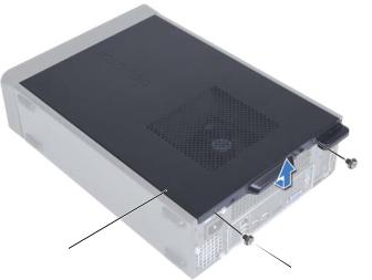
Removing the Computer Cover
NOTE: Ensure that you remove the padlock from the padlock rings (if applicable).
1Lay the computer on its side with the computer cover facing up.
2Using a screwdriver, remove the screws that secure the computer cover to the chassis.
3Release the computer cover by sliding it away from the front of the computer.
4Lift the computer cover and set it aside in a secure location.
Computer Cover |
|
17 |
|
1
 2
2
1 |
computer cover |
2 |
screws (2) |
Replacing the Computer Cover
1Connect all the cables and fold the cables out of the way.
2Ensure that no tools or extra parts are left inside the computer.
3Align the tabs at the bottom of the computer cover with the slots located along the edge of the chassis.
4Press the computer cover down and slide it toward the front of the computer.
5Replace the screws that secure the computer cover to the chassis.
6Place the computer in an upright position.
7Follow the instructions in "After Working Inside Your Computer" on page 11.
18 |
Computer Cover |

Fan Shroud
WARNING: Before working inside your computer, read the safety information that shipped with your computer and follow the steps in "Before You Begin" on page 9. For additional safety best practices information, see the Regulatory Compliance Homepage at dell.com/regulatory_compliance.
Removing the Fan Shroud
Prerequisites
1Remove the computer cover. See "Removing the Computer Cover" on page 17.
Fan Shroud |
|
19 |
|
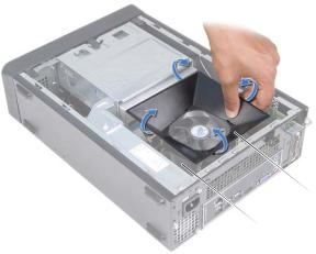
Procedure
1Press in on the fan shroud and lift it to release the tabs that secure the fan shroud to the processor fan and heat-sink assembly.
 2
2
 1
1
1 |
processor fan and heat-sink assembly |
2 |
fan shroud |
2 Lift the fan shroud and set it aside in a secure location.
Replacing the Fan Shroud
Procedure
1Place the fan shroud over the processor fan and heat-sink assembly.
2Gently press the fan shroud until the tabs on the fan shroud snap into place.
Postrequisites
1Replace the computer cover. See "Replacing the Computer Cover" on page 18.
2Follow the instructions in "After Working Inside Your Computer" on page 11.
20 |
Fan Shroud |
Memory Module(s)
WARNING: Before working inside your computer, read the safety information that shipped with your computer and follow the steps in "Before You Begin" on page 9. For additional safety best practices information, see the Regulatory Compliance Homepage at dell.com/regulatory_compliance.
Removing Memory Module(s)
Prerequisites
1Remove the computer cover. See "Removing the Computer Cover" on page 17.
2Remove the fan shroud. See "Removing the Fan Shroud" on page 19
Memory Module(s) |
|
21 |
|
Procedure
WARNING: The memory module(s) may become very hot during normal operation. Allow the memory module(s) to cool before touching them.
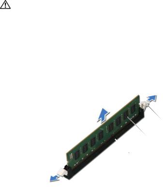
1Locate the memory module(s) on the system board. See "System Board Components" on page 15.
2Press out the securing clip at each end of the memory-module connector.
3Grasp the memory module and pull it upward.
If the memory module is difficult to remove, gently ease the memory module back and forth to remove it from the connector.
 3
3
 2
2
 1
1
1 |
memory-module connector |
2 memory module |
3 |
securing clips (2) |
|
22 |
Memory Module(s) |
Replacing Memory Module(s)
CAUTION: If the memory module is not installed correctly, your computer may not boot.
CAUTION: If you remove the original memory module(s) from your computer during a memory upgrade, keep them separate from any new memory module(s) that you may have, even if you purchased the new memory module(s) from Dell. If possible, do not pair an original memory module with a new memory module. Otherwise, your computer may not start properly.
Procedure
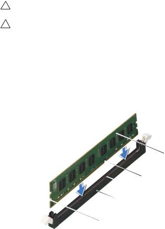
1Press out the securing clip at each end of the memory-module connector.
2Align the notch on the bottom of the memory module with the tab on the memory-module connector.
 5
5
|
|
|
4 |
|
|
|
3 |
|
|
|
2 |
|
|
|
1 |
1 |
cutouts (2) |
2 |
memory-module connector |
3 |
tab |
4 |
notch |
5 |
memory module |
|
|
Memory Module(s) |
|
23 |
|

CAUTION: To avoid damage to the memory module, press the memory module straight down into the connector while you apply equal force to each end of the memory module.
3Insert the memory module into the memory-module connector until the memory module snaps into position.
If you insert the memory module correctly, the securing clips snap into the cutouts at each end of the memory module.
 3
3
 2
2
|
1 |
|
1 |
securing clip (snapped in position) |
2 memory-module connector |
3 |
memory module |
|
24 |
Memory Module(s) |
Postrequisites
1Replace the fan shroud. See "Replacing the Fan Shroud" on page 20
2Replace the computer cover. See "Replacing the Computer Cover" on page 18.
3Follow the instructions in "After Working Inside Your Computer" on page 11.
4Connect your computer and devices to electrical outlets, and then turn them on.
If a message appears stating that the memory size has changed, press <F1> to continue.
Log on to your computer. To verify that the memory is installed correctly, click Start→ Control Panel→ System. Check the amount of memory (RAM) listed.
Memory Module(s) |
|
25 |
|
26 |
Memory Module(s) |

PCI-Express Cards
WARNING: Before working inside your computer, read the safety information that shipped with your computer and follow the steps in "Before You Begin" on page 9. For additional safety best practices information, see the Regulatory Compliance Homepage at dell.com/regulatory_compliance.
Removing the PCI-Express Cards
Prerequisites
1Remove the computer cover. See "Removing the Computer Cover" on page 17.
2Remove the fan shroud. See "Removing the Fan Shroud" on page 19.
PCI-Express Cards |
|
25 |
|
Procedure
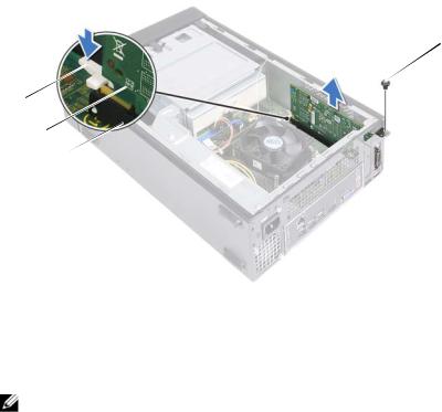
1Disconnect any cables connected to the card, if applicable.
2Remove the screw that secures the card to the chassis.
PCI-Express x1 card — Grasp the card by its top corners, and ease it out of its connector.
PCI-Express x16 card — Press down the securing tab, grasp the card by its top corners, and then ease it out of its connector.
4
1 
2 
3 
1 |
securing tab |
2 |
PCI-Express x16 card |
3 |
PCI-Express x16 card connector |
4 |
screw |
3If you are removing the card permanently, install a filler bracket in the empty card-slot opening.
NOTE: Installing filler brackets over empty card-slot openings is necessary to maintain FCC certification of the computer. The brackets also keep dust and dirt out of your computer.
26 |
PCI-Express Cards |

Replacing the PCI-Express Cards
Procedure
1Prepare the card for installation.
See the documentation that shipped with the card for information on configuring the card, making internal connections, or otherwise customizing it for your computer.
2Replace the PCI-Express card:
PCI-Express x1 card — Place the PCI-Express card in the connector on the system board and press down firmly. Ensure that the PCI-Express card is fully seated in the connector.
PCI-Express x16 card — Press down the securing tab and place the PCIExpress card in the connector on the system board and press down firmly. Ensure that the PCI-Express card is fully seated in the connector.
3Connect any cables that should be attached to the card.
See the documentation that shipped with the card for information about the card’s cable connections.
CAUTION: Do not route card cables over or behind the cards. Cables routed over the cards can prevent the computer cover from closing properly or cause damage to the equipment.
Postrequisites
1Replace the fan shroud. See "Replacing the Fan Shroud" on page 20.
2Replace the computer cover. See "Replacing the Computer Cover" on page 18.
3Follow the instructions in "After Working Inside Your Computer" on page 11.
4To complete the installation, see "Configuring Your Computer After Removing or Installing the PCI-Express Card" on page 28.
PCI-Express Cards |
|
27 |
|
Loading...