


Danby DPA085B1 Owner's Manual

• OWNER’S USE AND CARE GUIDE
• GUIDE D’UTILISATION ET SOINS DE
PROPRIÈTAIRE
PORTABLE AIR CONDITIONER
CLIMATISEUR PORTATIF
Model • Modèle • Modelo
MODEL • MODÈLE DPA085B1GB
Danby Products Limited, Ontario, Canada N1H 6Z9
Danby Products Inc., Findlay, Ohio, USA 45840
V1.12.10 DM
PORTABLE AIR CONDITIONER
Owner’s Use and Care Guide
• Welcome .............................................................
• Safety Instructions ..............................................
• Identifying Parts ..................................................
• Features ..............................................................
• Operating Instructions .........................................
• Installation Instructions .......................................
• Care and maintenance ........................................
• Troubleshooting ...................................................
• Warranty ..............................................................
CLIMATISEUR PORTATIF
Guide d’utiliser et soin de propriètaire
• Bienvenue ...........................................................
• Consignes de Sécurité Important .......................
• l'identification des pièces ....................................
• Caractéristiques ..................................................
• Consignes d’utilisation ........................................
• Instructions d’installation .....................................
• Soins et entretien ................................................
• Dépannage .........................................................
• Garantie ..............................................................
Contents
2
3-4
4-6
6-7
8-9
10-14
15
16
17
18
19-20
21-22
23
24-25
26-30
31
32
33
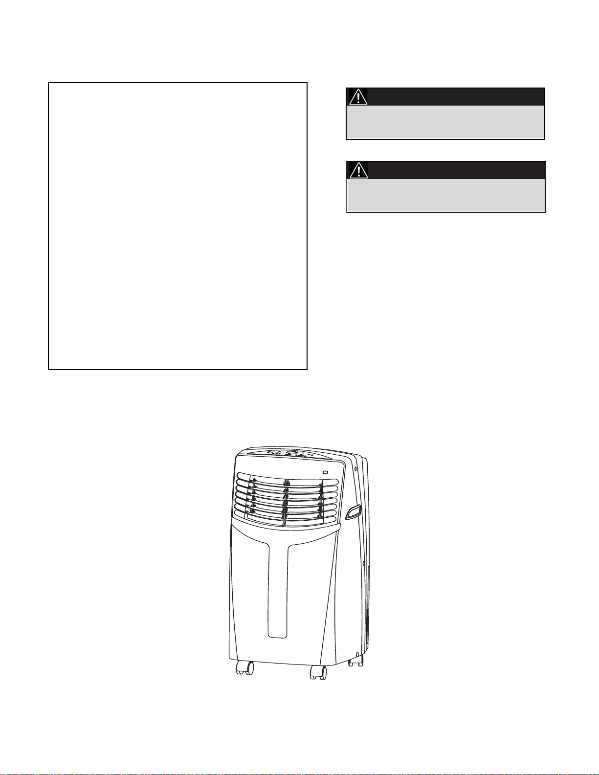
CAUTION:
PRECAUTION:
Read and follow all safety rules and
operating instructions before first use of this
product.
Veuillez lire attentivement les consignes de
sécurité et les instructions d’utilisation avant
l’utilisation initiale de ce produit.
Model • Modèle • Modelo DPA085B1GB
1

Welcome
Thank you for choosing a Danby appliance to provide you and your family with all of the “Home Comfort” requirements
of your home, cottage, or office. This Owner’s Use and Care Guide will provide you with valuable information necessary
for the proper care and maintenance of your new appliance. If properly maintained, your Danby appliance will give you
many years of trouble free operation. Please take a few moments to read the instructions thoroughly and familiarize
yourself with all of the operational aspects of this appliance.
Your Danby Portable Air-Conditioner is a multi-functional room air-exchanging, air-processing appliance, designed to
offer you air conditioning, dehumidifying and Independent fan functions. Each individual mode is featured with “oscillating” air swing capabilities. This unit can be conveniently moved from room to room within your home and set up in just
minutes. Imagine the convenience of four Season Home Comfort at your fingertips, anywhere, anytime.
For easy reference, may we suggest that you attach a copy of your sales slip/receipt to this page, along with the following information, located on the manufacturers nameplate on the rear panel of the unit.
This information will be necessary if your unit requires servicing and/or for general inquiries. To contact a
Customer Service Representative, call Danby TOLL FREE: 1-800-263-2629
Model Number:
Serial Number:
Date of Purchase:
2
Important Safety Information
READ AND FOLLOW ALL SAFETY INSTRUCTIONS
SAFETY
PRECAUTIONS
To prevent injury to the user or other people and property damage, the following instructions must be followed.
Incorrect operation resulting from to ignoring these instructions may cause harm or damage.
Your air conditioner should be used in such a way that it is protected
from moisture. e.g. condensation, splashed water, etc. Do not place or
store your air conditioner where it can fall or be pulled into water or
any other liquid. Unplug unit immediately if this occurs.
Always transport your air conditioner in a vertical position and place
on a stable, level surface during use.If the unit is transported laying
on it’s side it should be stood up and left unplugged for 4 hrs.
Turn off the unit when not in use.
Always contact a qualified person to perform repairs. If the power cord
is damaged it must be repaired by a qualified technician.
Keep clearance of at least 30cm all around the unit from walls, furniture and curtains.
If the air conditioner is knocked over during use, turn off the unit and
unplug it immediately.
Always use the switch on the control panel to turn off unit.
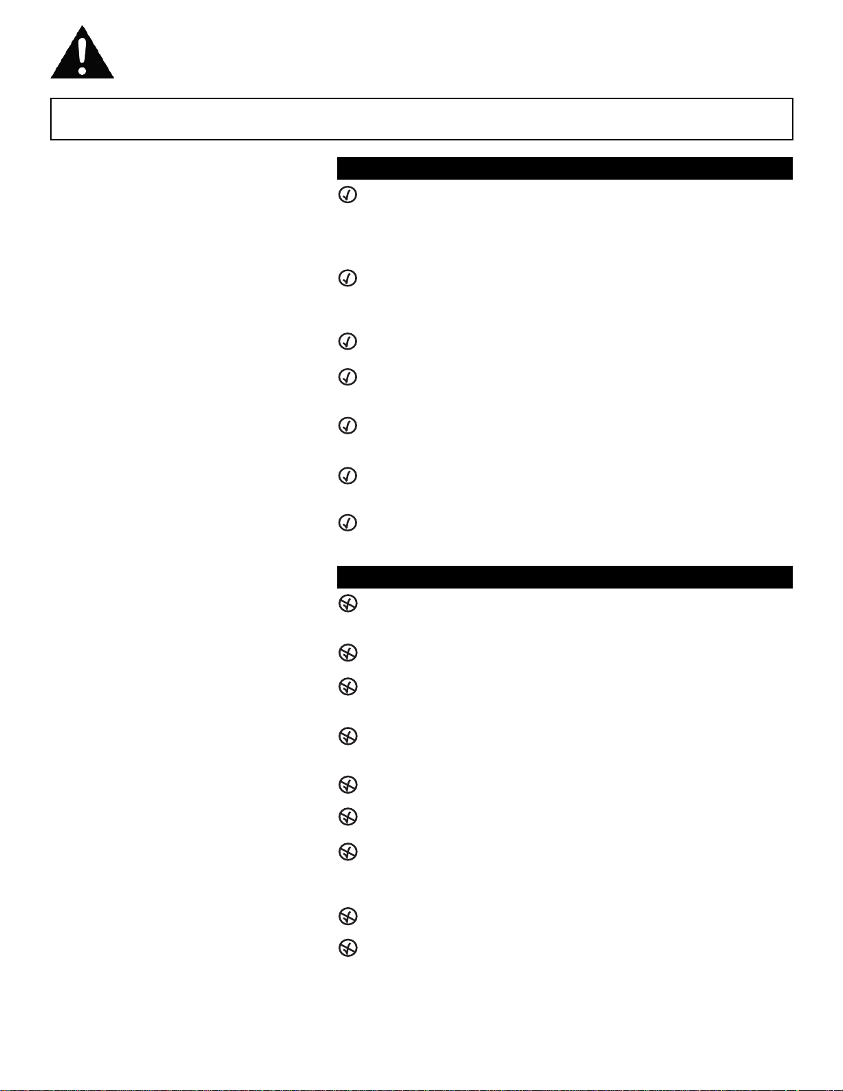
ALWAYS DO THIS
Do not operate your air conditioner in a wet room such as a bathroom
or laundry room.
Do not touch the unit with wet or damp hands.
Do not press the buttons on the control panel with anything other than
your fingers.
Do not remove any fixed components. Never use this appliance if it is
not working properly, or if it has been dropped or damaged.
Never use the plug to start and stop the unit.
Do not cover or obstruct the inlet or outlet grilles.
Do not use hazardous chemicals to clean or come into contact with
the unit. Do not use the unit in the presence of inflammable
substances or vapour such as alcohol, insecticides, petrol,etc.
Do not allow children to operate the unit unsupervised.
Do not use this product for functions other than those described in this
instruction manual.
NEVER DO THIS
3
Important Safety Information
READ AND FOLLOW ALL SAFETY INSTRUCTIONS
To prevent injury to the user or other people and property damage, the following instructions must be followed.
Incorrect operation resulting from to ignoring these instructions may cause harm or damage.
ENERGY SAVING
TIPS
• Use the unit in the recommended room size.
• Locate the unit where furniture cannot obstruct the air flow.
• Keep blinds/curtains closed during the sunniest part of the day.
• Keep the filters clean.
• Keep doors and windows closed to keep cool air in and warm air out
(cooling mode).
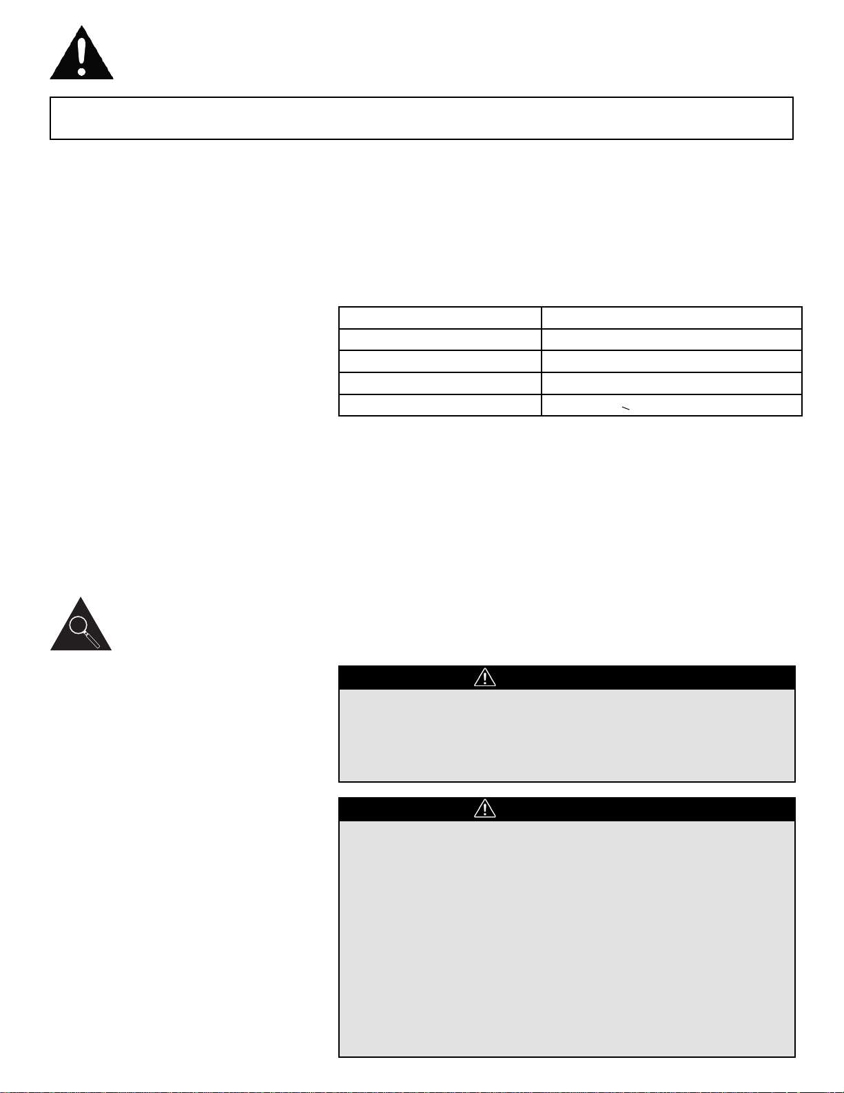
OPERATING
CONDITION
The air conditioner must be operated within the temperature range
indicated below:
MODE
COOL
DRY
*HEAT (heat pump type)
*HEAT (electrical or heat pump)
ROOM TEMPERATURE
17°C (62°F) ~ 35°C (95°F)
13°C (55°F) ~ 35°C (95°F)
5°C (41°F) ~ 30°C (86°F)
<30°C / 86°F
(*) Optional feature, some models may not have this feature.
Note: Performance may be reduced outside of these operating
temperatures.
TOOLS FOR WINDOW
KIT INSTALLATION
1. Screwdriver (medium size, Phillips)
2. Tape measure or ruler
3. Knife or scissors
4. Saw (In the event that the window kit needs to be cut down in size
because the window is too narrow for direct installation).
See www.danby.com for general instruction guide.
Identifying Parts
WARNING
• Do not store or use gasoline or other flammable vapors and
liquids in the vicinity of this or any other appliance.
• Avoid fire hazard or electric shock. Do not use an extension cord
or an adaptor plug. Do not remove any prong from the power
cord.
ELECTRICAL
INFORMATION
WARNING
• Be sure the electrical supply is adequate for the model you have
chosen. This information can be found on the serial plate, which
is located on the side of the cabinet and behind the grille.
• Be sure the air conditioner is properly grounded. To minimize
shock and fire hazards, proper grounding is important. The
power cord is equipped with a three-prong grounding plug for
protection against shock hazards.
• Your air conditioner must be used in a properly grounded wall
receptacle. If the wall receptacle you intend to use is not
adequately grounded or protected by a time delay fuse or circuit
breaker, have a qualified electrician install the proper receptacle.
• Ensure the receptacle remains accessible after the unit is
installed.
4

Identifying Parts
ACCESSORIES
PARTS
PART NAME
QUANTITY
Exhaust hose and Adaptor
B (flat mouth)
1 set
Adaptor B (round mouth)*
1 set
Wall Exhaust Adaptor A*
1 pc
Expansion Plug and
wood screw*
4 pc
Window Slider Kit and bolt
1 set
Foam seal
3 pc
Remote Controller and
Battery (For remote control
models only)
1set
Drain hose
1pc
NOTE: Optional parts(*), some models do not include them.
• Ensure that all the accessories are included in the package and refer to the installation
instructions for their usage.
NOTE: All the illustrations in this manual are for explanatory purposes only. Your air conditioner
may be slightly different.
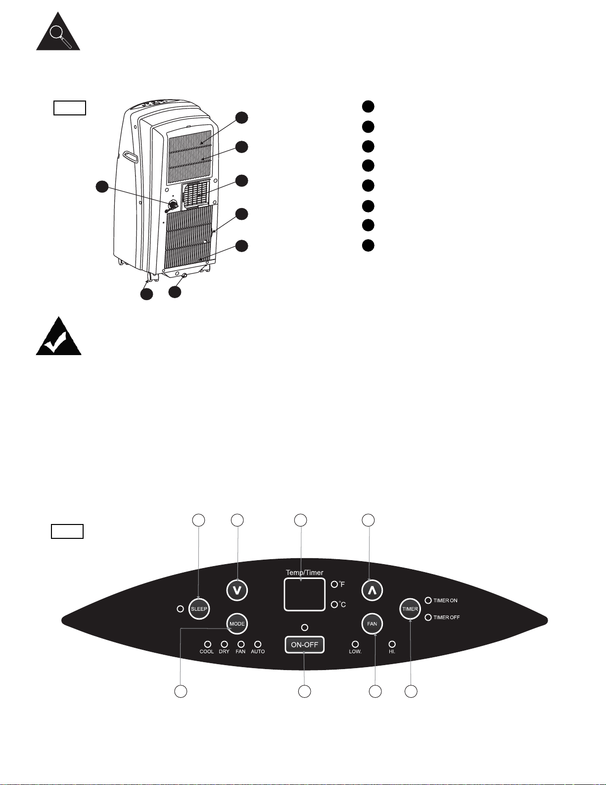
UNIT STRUCTURE
FRONT
1
2
3
4
Control Panel
Horizontal Louver Blade
(adjusts manually)
Carrying Handle
(both sides)
Remote Signal Receptor
Front Panel
Fig.1
5
5
ION
FOLLOW
ME
RESETLOC K
DISPLAY
LED
TIMEROFF
TURBO
MODE
SWING
TEMP
ECONOMY
ON/OFF
FANSPEED
TIMERON
AUTO
COOL
DRY
HEAT
F
HIGH
MED
LOW
AN
1
3
4
2
5
11
333322
44 5566
77
Identifying Parts
REAR
6
7
8
9
10
11
12
13
Upper Air Filter (behind the grille)
Air Outlet
Castor
Air Intake
Drain Outlet
Air Intake
Lower Air Filter (behind the grill)
Bottom tray drain outlet
Fig.2
Features
ELECTRONIC CONTROL
INSTRUCTIONS
Before you begin, thoroughly familiarize yourself with the control panel
and remote controller and all its functions. Select the functions you desire
based on the associated symbol.
The unit can be controlled by the control panel alone or with the remote
controller.
NOTE: This manual does not include Remote Controller Operation. Refer
to the <<Remote Controller Instructions>> packed with the unit for this
information.
Fig.3
6
6
10
13
8
9
7
12
11

Features
1
ELECTRONIC CONTROL
INSTRUCTIONS
MODE select button
Selects the appropriate operating mode. Each time you press the button, a mode is selected in a sequence that goes from AUTO, COOL,
DRY, FAN and HEAT(cooling models only without HEAT feature). The
mode indicator light illuminates in the corresponding mode setting.
TIMER button
Used to initiate the AUTO ON start time and AUTO OFF stop time program, in conjuction with the up arrow & down arrow buttons.
POWER button
Turns power on/off.
SLEEP button
Used to initiate the SLEEP operation.
FAN button
Controls the fan speed. Press to toggle between two fan speeds: LOW
and HIGH. The fan speed indicator light indicates different fan settings.
UP and DOWN buttons
Used to adjust (increase /decrease) temperature settings (1°C/2°F
increments) in a range of 17°C(62°F) to 30°C(88°F) or the TIMER setting in a range of 0~24hrs. The control is capable of displaying
temperature in degrees Fahrenheit or degrees Celsius. To convert
from one to the other, press and hold the Up and Down buttons at the
same time for 3 seconds.
LED Display
Shows the set temperature in °C or °F and the Auto-timer settings.
While on DRY and FAN modes, it shows the room temperature.
Also displays the following error codes:
E1 - Room temperature sensor error-Unplug the unit and plug
it back in. If error repeats, call for service.
E2 - Evaporator temperature sensor error- Unplug the unit and
plug it back in. If error repeats, call for service.
E4 - Display panel communication error - Unplug the unit and
plug it back in. If error repeats call for service.
P1 - Bottom tray is full - Connect the drain hose and drain the
collected water away. If error repeats, call for service.
ION button(optional)
By pressing the ION button, the ion generator is energized and will
help to remove pollen and impurities from the air, and trap them in the
filter. Press it again to stop the function.
2
3
4
5
7
8
7
6

Operating Instructions
OPERATING MODES
COOL mode
- Press the "MODE" button until the "COOL" indicator light comes on.
- Press the up / down arrows to select your desired room temperature.
The temperature can be set within a range of 17°C-30°C / 62°F-88°F.
- Press the "FAN SPEED" button to choose the fan speed.
HEAT mode (applicable models only)
- Press the "MODE" button until the "HEAT" indicator light comes on.
- Press the ADJUST buttons "up arrow" or "down arrow" to select your
desired room temperature. The temperature can be set within a range of
17°C-30°C / 62°F-88°F.
- Press the "FAN SPEED" button to choose the fan speed. For some
models, the fan speed can not be adjusted under HEAT mode.
DRY mode
- Press the "MODE" button until the "DRY" indicator light comes on.
- Under this mode, you cannot select a fan speed or adjust the
temperature. The fan motor operates at LOW speed.
- Keep windows and doors closed for the best dehumidifying effect.
- Do not use the window hose under this mode.
AUTO mode
- When you set the air conditioner in AUTO mode, it will automatically
select cooling, heating (applicable models only) or fan only operation
depending on what temperature you have selected and the room
temperature.
- The air conditioner will adjust the room temperature automatically to
the temperature point set by you.
- Under AUTO mode, you can not select the fan speed.
FAN mode
- Press the "MODE" button until the "FAN " indicator light comes on.
- Press the "FAN SPEED" button to choose the fan speed. The
temperature cannot be adjusted.
- Do not use the window hose under this mode.
TIMER mode
- To initiate the TIMER OFF function, press the timer button when the unit
is on. It indicates the Auto Stop program is initiated.
- To initiate the TIMER ON function, press the timer button when the unit
is off. It indicates the Auto Start program is initiated.
- Press and hold the UP or DOWN button to change the Auto-time by half
hour increments, up to 10 hours, then at 1 hour increments up to 24
hours. The control will count down the time remaining until the unit
starts or stops.
- The selected time will program in 5 seconds and the system will
automatically revert back to display the previous temperature setting.
- Turning the unit ON or OFF at any time or adjusting the timer setting
to 0.0 will cancel the Auto Start/Stop timed program.
- When the malfunction (E1 or E2) occurs, the Auto Start/Stop program
will be cancelled.
SLEEP cycle
This unit features an operation mode that is designed to keep you
comfortable while sleeping, and save you money on your energy bill.
Simply press the sleep button. Depending on whether the unit is in heating or cooling mode, the temperature will either increase (cooling mode)
or decrease (heating mode) by 1°C / 2°F every half hour for 1 hour. It will
then hold this new temperature for 7 hours before returning to the original
temperature setting and resuming normal operation.
NOTE: This feature is unavailable in FAN and DRY mode.
8

Operating Instructions
POWER OUTAGE
In the case of a power outage or interruption, the unit will automatically
re-start with the default settings after the power is restored.
Wait 3 minutes before resuming operation
After the unit has stopped, it can not operate for the first 3 minutes. This
is to protect the unit. Operation will automatically start after 3 minutes.
AIR FLOW DIRECTION
ADJUSTMENT
Adjust the air flow direction manually (Fig. 4):
• The louver can be set to the desired position manually.
- Do not place any heavy objects or other loads on the louver, doing so
will cause damage to the unit.
- Ensure the louver is fully opened under heating operation.
Fig.4
9
Adjust
manually

Installation Instructions
LOCATION
• The air conditioner should be placed on a firm foundation to minimize
noise and vibration. For safe and secure positioning, place the unit on a
smooth, level floor strong enough to support the unit.
• The unit has casters to aid placement, but it should only be rolled on
smooth, flat surfaces. Use caution when rolling on carpeted surfaces.
Use caution and protect floors when rolling over wood floors. Do not
attempt to roll the unit over objects.
• The unit must be placed within reach of a properly rated grounded
socket.
• Never place any obstacles around the air inlet or outlet of the unit.
• Allow at least 30cm of space away from the wall for efficient air
conditioning.
WINDOW SLIDER KIT
INSTALLATION
Your window slider kit has been designed to fit most standard vertical and
horizontal window applications, However, it may be necessary for you to
modify some aspects of the installation procedures for certain types of
windows. Please refer to Fig. 6& Fig.7 for minimum and maximum window openings. The window slider kit can be fastened with a screw (see
Fig.8).
NOTE: If the window opening is less than the mentioned minimum length
of the window slider kit, cut the end without the whole in it short enough
to fit in the window opening. Never cut out the hole in window slider
kit. (visit www.danby.com for general instruction videos.)
30cm
30cm
Fig.5 Fig.6
Fig.7 Fig.8
Vertical
Window
Window Slider Kit
Minimum:56.2cm(1.84ft).
Maxmum:98.2cm(3.22ft).
Horizontal
Window
Window Slider Kit
Minimum:56.2cm(1.84ft).
Maxmum:98.2cm(3.22ft).
Screw
Window
slider
kit
10
 Loading...