

Owner’s Use and Care Guide
Guide d’utilisation et soins de Propriètaire
Model • Modèle
DPAC12010H
V1.12.09 JF
CAUTION: Read and
follow all safety rules
and operating
instructions before
first use of this
product.
MISE EN GARDE:
Veuillez lire
attentivement les
consignes de sécurité
et les directives
d’utilisation avant
l’utilisation initiale
de ce produit.
PORTABLE AIR CONDITIONER
Owner’s Use and Care Guide . . . . . . . . . . . . . . . . . . . . . . . . . . . . . . . . . . . . . . . . . 1 - 10
• Welcome
• Part Identification
• Important Safety Information
• Installation
• Operation
• Care and Maintenance
• Troubleshooting
• Warranty
CLIMATISEUR PORTATIF
Guide d’utilisation et soin de Propriètaire . . . . . . . . . . . . . . . . . . . . . . . . . . . . . . 11 - 20
• Bienvenue
• Indentification de Partie
• Consignes de Sécurité Important
• Installation
• Fonctionnement
• Soins et Entretien
• Garantie
KEEP THESE INSTRUCTIONS FOR FUTURE REFERENCE:
If the unit changes ownership, be sure this manual accompanies the unit.
CONSERVER CES INSTRUCTIONS POUR CONSULTATION ULTÉRIEURE:
En cas de revente du l’appareil, ce manuel doit être inclus avec l’appareil.
Danby Products Ltd, Guelph, Ontario Canada N1H 6Z9
Danby Products Inc, Findlay, Ohio USA 45840
Thank you for choosing a Danby Premiere appliance to provide you and your family with all of the
“Home Comfort” requirements of your home, cottage, or office. This Owner’s Use and Care Guide
will provide you with valuable information necessary for the proper care and maintenance of your
new appliance. If properly maintained, your Danby appliance will give you many years of trouble
free operation. Please take a few moments to read the instructions thoroughly and familiarize yourself
with all of the operational aspects of this appliance.
Your Danby Portable Air-Conditioner is a multi-functional room air-exchanging, air-processing
appliance, designed to offer you the functions of; Air Conditioning, Dehumidifying, and Independent
Fan. Each individual mode is featured with “oscillating” air swing capabilities. This unit can be
conveniently moved from room to room within your home and set up in just minutes. Imagine the
convenience of 4 Season Home Comfort at your fingertips, anywhere, anytime.
For easy reference, may we suggest you attach a copy of your sales slip/receipt to this page, along
with the following information, located on the manufacturers nameplate on the rear panel of the unit.
Model Number:
Serial Number:
Date of Purchase:
This information will be necessary if your unit requires servicing and/or for general inquiries. To contact a
Customer Service Representative, call Danby TOLL FREE: 1-800-26- (1-800-263-2629)
WELCOME
1
READ ALL SAFETY INFORMATION BEFORE USING
1) Check available power supply and resolve any wiring
problems BEFORE installation and operation of this unit.
All wiring must comply with local and national electrical
codes and be installed by a qualified electrician. If you have
any questions regarding the following instructions, contact a
qualified electrician.
2) This appliance draws 10.8 nameplate amps under Cooling
Mode and may be used in any properly wired, general
purpose 15 amp household grounded receptacle.
3) For your safety and protection, this unit is grounded through
the power cord plug when plugged into a matching wall
outlet. If you are not sure whether the wall outlets in your
home are properly grounded, please consult a qualified
electrician.
WARNING: Improper connection of the grounding plug can
result in risk of Fire, Electric Shock, and/or injury to Persons
associated with the appliance. Check with a qualified service
representative if in doubt that the appliance is properly grounded.
4) DO NOT USE PLUG ADAPTERS OR EXTENSION
CORDS WITH THIS UNIT. If it is necessary to use an
extension cord with this unit, use an approved “air
conditioner” extension cord only (available at most local
hardware stores).
5) To avoid the possibility of personal injury, always
disconnect the power supply to the unit before installing
and/or servicing.
TABLE 1
Suggested Individual Branch Circuit
Nameplate Amps *AWG Wire Size
10.8 16
AWG- American Wire Gauge
*Based on copper wire at 105°C temperature rating.
TABLE 2
Receptacle and Fuse Types
Rated Volts 125
Amps 15
Wall Outlet
Fuse Size 15
Time Delay Fuse Plug Type
(or Circuit Breaker)
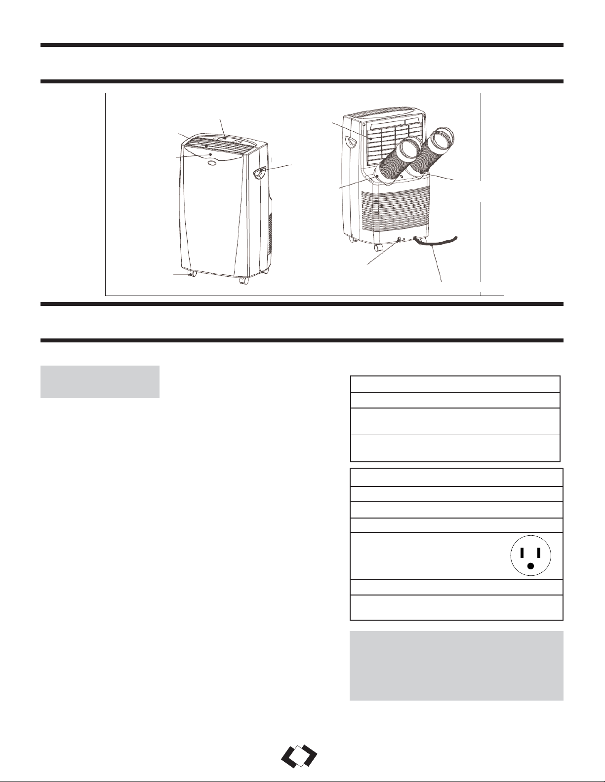
Control Panel
Air Outlet
Signal Receptor
Castor
Air Intake
(Evaporator)
Handle
Air Intake Hose
Air Outlet Hose
Water Outlet Drain
Power Supply Cord
2
PART IDENTIFICATION
CAUTION: Do not leave this unit
unattended in a space where people or
animals that cannot react to a failed unit
are located. A failed unit can cause
extreme overheating or death in such an
enclosed, unattended space.
ELECTRICAL
SPECIFICATIONS
IMPORTANT SAFETY INFORMATION

The power cord supplied with this air conditioner contains a device that senses damage to
the power cord. To test if your power cord is working properly, you must do the following:
Your Kenmore appliance is designed to be highly efficient in energy savings. Follow
these recommendations for greater efficiency.
1) Select a thermostat setting that suits your
comfort needs and leave at that chosen setting.
2) The air filter is very efficient in removing
airborne particles. Keep the air filter clean at all
times.
3) Use drapes, curtains or shades to keep direct
sunlight from penetrating and heating room, but
do not allow drapes or curtains to obstruct the air
flow around the unit.
4) Start your air conditioner before the outdoor air
becomes hot and uncomfortable, to avoid an initial
period of discomfort while the unit is cooling off the
room. Use of the automatic start/stop programmable
TIMER feature can be a major asset in this regard if
utilized to the fullest extent.
5) When outdoor temperatures are cool enough, turn the
air conditioner off and use the FAN MODE on High,
Medium or Low. This circulates indoor air,providing
some cooling comfort while utilizing less electricity.
NOTE: The power cord supplied with this air
conditioner contains a current leakage detection device
designed to reduce the risk of fire. In the event the
power supply cord is damaged, it cannot be repaired
and must be replaced with a new cord from the product
manufacturer.
• Under no circumstances should this device be used to
turn the unit on or off.
• The “RESET” button must always be pushed in
(engaged) for correct operation.
• The power supply cord must be replaced if it fails to
reset when the “TEST” button is pushed in.
1) Connect the power supply cord to an electrical outlet.
2) The power supply cord has two buttons located on
the head of the plug. One button is marked
“TEST”, and the other is marked “RESET”. Press
the “TEST” button; you will hear a click as the
“RESET” button pops out.
3) Press the “RESET” button; you will hear a click
as the button engages.
4) The power supply cord is now energized and
supplying electricity to the air conditioner (on
some products this is also indicated by a light on
the plug head).
3
IMPORTANT SAFETY INFORMATION
POWER
SUPPLY CORD
ENERGY-
SAVING TIPS
Air Conditioning Mode ONLY
Your window kit has been designed to fit most
standard “vertical”/”horizontal” windows up to a
maximum height of 80” (203cm). For vertical
window applications, multi lock positions are
provided on the edge of each slider section to secure
each sliding section together.
1) Select a suitable location, making sure you have
access to an electrical outlet.
2) Install the flexible hose to the rear side of the unit.
Insert the hose collar on top of the exhaust opening
and twist to lock into position.
3) Install the adjustable Window Slider Kit as
required (see Fig. 3a & 3b).
4) Install the opposite end of the flexible exhaust
hose into the window exhaust adapter.
5) Install the window exhaust adapter into the
opening in the slider section, making sure the
window slider sections are secure.
6) Plug the unit into a 115V/60Hz grounded electrical
outlet.
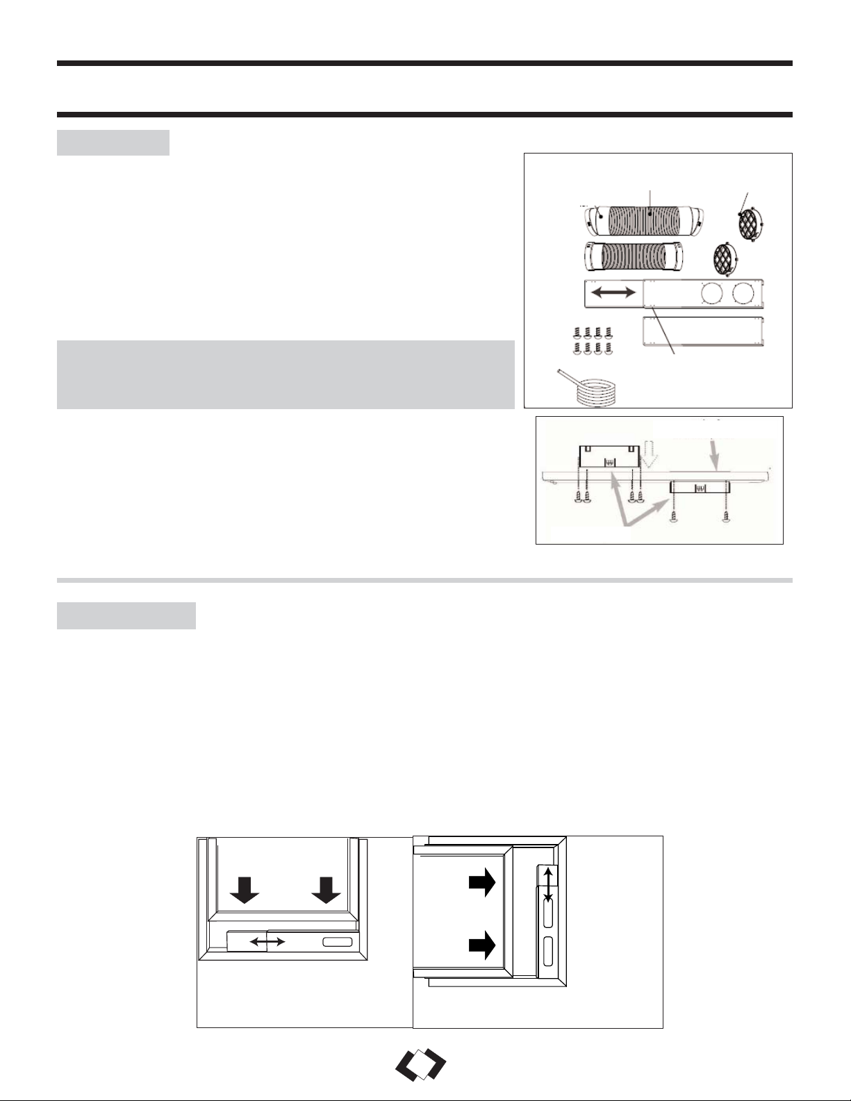
Window Slider Kit:
Min.: 28 1/3” (67.5cm)
Max.: 80” (203cm)
Window
Slider Kit:
Min.: 28
1
/3”
(72cm)
Max.: 80”
(203cm)
Horizontal Window
Vertical
Window
There should be at least 11.8” (30cm) clearance between the unit
and any other objects or building structures, and should be installed
on a level surface. The unit does not have to be vented outside
during Dehumidifying or Fan Only mode operation.
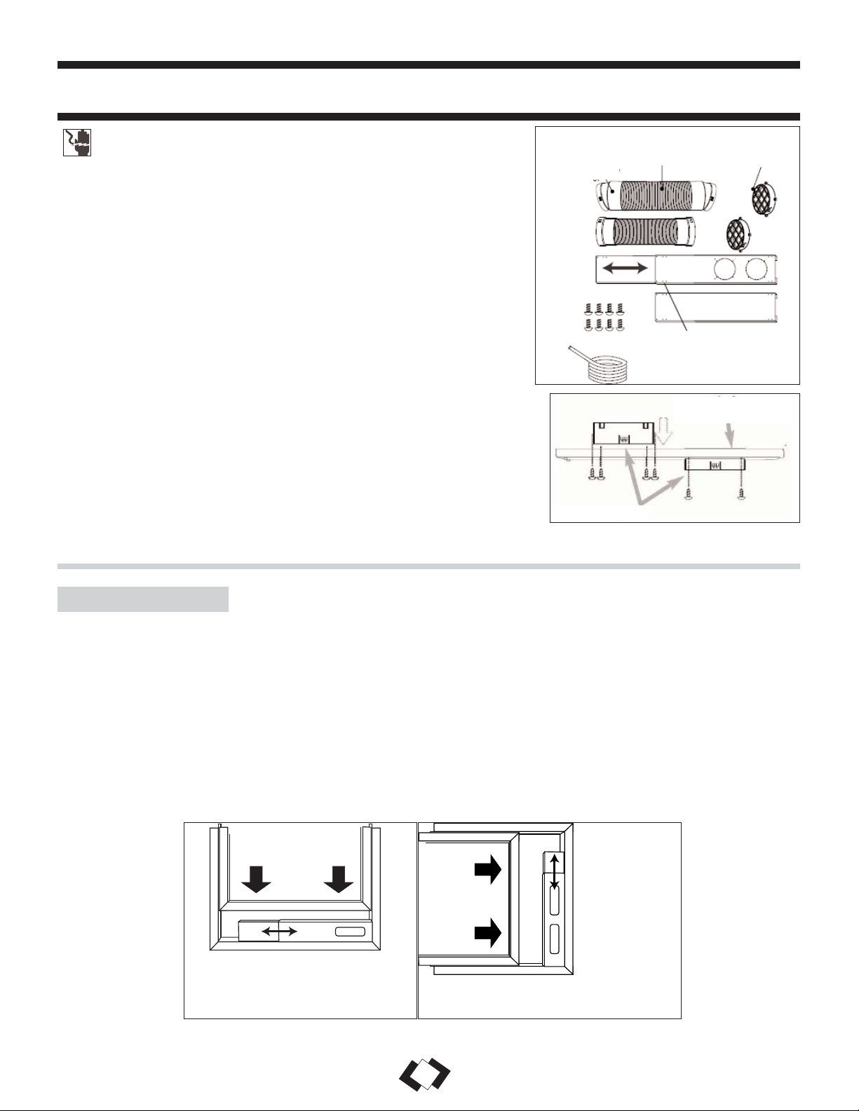
Flexible Exhaust Hose (13cm) & Exhaust nozzle connector (2
pcs) from 17
1
/10” (45cm) up to 53 1/6” (135cm)
Adjustable window door slider kit (3 pcs) from 28 1/3
”(72cm) up to
80” (203cm)
Fixture..... (2 pcs)
Screws......(12 pcs)
NOTE: The exhaust/window kit must be installed at all times when
the unit is operating under AIR CONDITIONING mode.
ELECTRIC SHOCK HAZARD: To avoid the possibility of personal injury, disconnect
power to the unit before installing or servicing.
Back of Window Pane
Tube Adapters
Fig. 2
Instructions for Assembling the Window Kit- Fig. 2
1) Insert tube adapters through the back of the window panel.
2) Secure each tube adapter with four screws through the front of the
window panel.
3) Insert window panel extensions into window panel. Lightly tighten
the screws in the window panel to hold the extensions in place.
Fig. 3a
Fig. 3b
4
INSTALLATION
WARNING
WINDOW KIT
Fig. 1
INSTALLATION ACCESSORIES
Flexible Exhaust Hose
Exhaust Nozzle
Connector
Fixture
Adjustable Window Slider Kit:
28 1/3” (72cm)- 80” (203cm)
Screws
Water hose (79”/ 200cm)
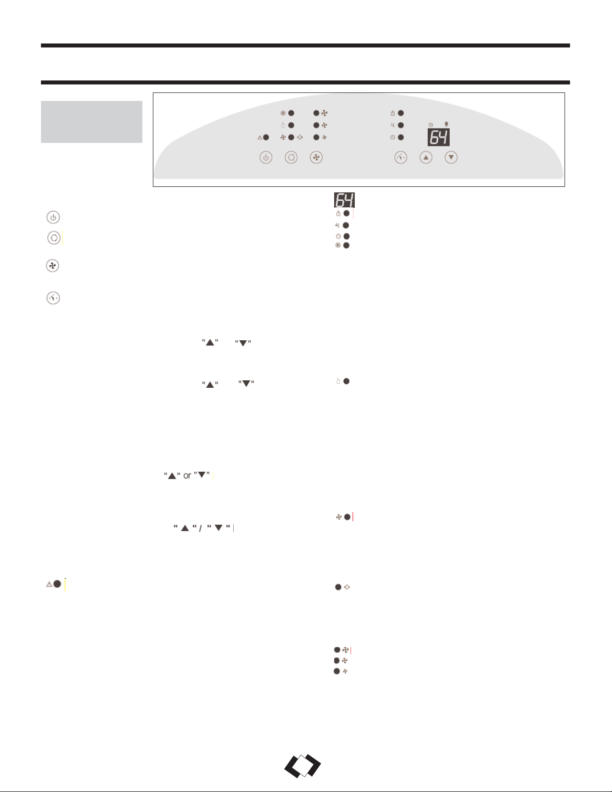
KEY PAD FUNCTIONS
POWER SWITCH: Turns unit ON/OFF
MODE: Allows you to scroll through and select
desired operating mode.
FAN: Select from three different fan settings; High,
Medium, and Low.
AUTO-TIMER
AUTO-TIMER Adjust:
Auto off- With machine in running mode, press timer
button to set timer control. Press or buttons to
select number of hours you would like the unit to run
before it automatically shuts off.
Auto on- With machine in stand by mode, press timer
button to set timer control. Press or buttons to
select number of hours before the unit automatically
starts running in air conditionning mode.
NOTE: The time is adjustable between 1-24 hours.
TEMPERATURE Adjust:
• Used for adjusting the thermostat.
• The default display is room temperature.
• In cooling mode, when button is pressed, the
set temperature is displayed and may be adjusted. After
15 seconds the display will revert back to room
temperature. Temperature is only adjustable in cool mode.
Timer & Temp. Display
Room Temp.
Temp. Set
Timer Set
MODE INDICATOR LIGHTS
Cooling Mode
When cool mode is selected, the indicator light
will shine GREEN. During the cooling mode, the
air is cooled and hot air is exhausted outside
through the exhaust tube. Adjust fan speed to suit
your desired comfort level.
Note: The air exchange h ose must vent outside
the room when using cool mode.
Dehumidify Mode
When dehumidify mode is selected, the indicator
light will shine ORANGE. Air is
dehumidified as it passes through the unit,
without being in full cooling mode. The fan will
operate on med. speed. If room temperature is
>25°C (77°F), fan speed can be adjusted;
otherwise fan speed is fixed to “low”.
Note: The warm air exchange hose must vent
inside the room when using Dehumidify Mode,
not outside as it does when cooling. If the unit is
vented outside, some cooling will occur.
Fan Mode
When fan mode is selected, the indicator will
shine YELLOW. Air is circulated throughout the
room with no cooling.
Note: The unit does not need to be vented in Fan
mode.
Heating Mode
When heating mode is selected the indicator will
shine RED. Heating is activated only when the
ambient temperature is below 25°C (77°F).
FAN SPEED INDICATOR LIGHTS
High Fan
Medium Fan
Low Fan
NOTE: By pressing both buttons at the
same time for more than 3 seconds, the display will
toggle between Celsius and Fahrenheit.
STATUS DISPLAY
Warning Light
Condensed water may accumulate in the unit. If the
internal tank becomes full, the Warning signal in the LCD
Display will light up and the unit will not operate until the
unit has been drained.
NOTE: After switching the air conditioner off, you must wait 3 minutes before switching it back on again.
5
OPERATION
FEATURES OF
THE CONTROL
PANEL

AIR CONDITIONER
Note: The exhaust hose must be properly vented (outdoors) during air conditioning mode.
1) Press the POWER SWITCH key (Fig. A) to switch on the unit, and the previous
set temperature will be shown in the temperature display area of the control panel.
2) Press the MODE key (Fig. B) until the COOL indicator light illuminates on the
control panel (Fig.C). Each depression of the MODE key will advance to a different
mode setting (Cool-Dehumidifier-Fan-Heat-Auto)
3) Press the appropriate increase or decrease buttons (Fig. D) to select a
suitable operating temperature setting. Temperature settings are adjustable between
16°C (61°F) to 32°C (89°F).
4) Press the FAN key (Fig. E) to select the desired fan speed setting (Auto-High-
Med.-Low). Your selection will appear on the control panel (each depression of the
fan key will advance to a different setting).
• Cooling stops automatically when the set temperature is achieved. Cooling resumes
when the room temperature rises above the “set” temperature level.
DEHUMIDIFIER
Note: During dehumidifier mode, the exhaust hose does not have to be vented outdoors.
1) Press the ON/OFF key pad to switch the unit on (Fig. A)
2) Press the MODE key (Fig. B) until the DRY indicator illuminates on the control
panel (Fig.G). Each press of the MODE key will advance to a different mode
setting (Cool-Dehumidifier-Fan-Heat-Auto).
3) If room temperature is >25°C (77°F), fan speed can be adjusted. Press the FAN key
(Fig. E) to select the desired FAN SPEED setting. Your selection will appear on the
control. Each depression of the fan key will advance to a different fan speed as
shown in Fig. F. Otherwise fan speed is fixed to “low”.
NOTE: The warm air exchange hoses must vent inside the room when using
Dehumidifier Mode, not outside as in Cooling Mode.
FAN
Note: During Fan Mode, the exhaust hose does not have to be vented outdoors.
1) Press the POWER SWITCH key to turn the unit on (Fig. A).
2) Press the MODE key (Fig. B) until the FAN indicator illuminates on the control
panel (Fig. H). Each press of the MODE key will advance to a different mode
setting (Cool-Dehumidifier-Fan-Heat-Auto).
3) Press the FAN Key (Fig. E) to select the desired FAN SPEED setting. Your
selection will appear on the control panel. Each press of the fan key will advance to
a different fan speed (High- Med- Low) as shown in Fig. F.
HEAT
Note: During Heat Mode, the exhaust hose does not have to be vented outdoors.
1) Press the POWER SWITCH key (Fig. A) to switch on the unit, and the previous set
temperature will be shown in the temperature display area of the control panel.
2) Press the MODE key (Fig. B) until the Heat indicator light illuminates on the control
panel (Fig. I). Each depression of the MODE key will advance to a different mode
setting (Cool- Dehumidifier- Fan- Heat).
3) Press the appropriate increase or decrease buttons (Fig D) to select a
suitable operating temperature setting. Temperature settings are adjustable between
16°C (61°F) to 27°C (80°F).
4) Press the FAN key (Fig. E) to select the desired fan speed setting (High- Med.Low). Your selection will appear on the control panel (each depression of the fan
key will advance to a different setting)
• Heating stops automatically when the set temperature is achieved. Heating resumes
when the room temperature rises above the “set” temperature level.
Fig. A
Fig. F
Fig. G
6
OPERATION (cont’d)
Fig. B
Fig. C
Fig. D
Fig. E
High
Medium
Low
Orange
Green
Fig. H
Yellow
Fig. I
Red

The AUTO-TIMER feature offers a unique selection of multiple choice, fully automatic
on and/or off (start/stop) programs between 1-24 hours under any one mode of your Home
Comfort unit.
The programs are as follows:
a) Auto-Off: Pre-select a time that will turn off the
unit automatically (between 1-12hrs).
b) Auto-On: Pre-select a time that will turn on the
unit automatically (between 1-12hrs).
c) Auto-On & Auto Off: Pre-select a time that will
turn the unit ON / OFF automatically at specified
times (between 1-12hrs).
Note: These functions must be performed daily, as
the program is automatically canceled/erased after the
program has ended.
Control Buttons:
1) Power Switch
2) Mode
3) Fan Speed
4) On / Off Timer
5) Time / Temperature Set
• Used for adjusting the timer and temperature.
• The default display on control panel is room temperature.
• When or key is pressed in cool mode, the set temperature is displayed
and may be adjusted. After 10 seconds, the display will revert back to room
temperature.
• Timer setting is available from 1-24 hours by pressing or keys.
To operate the hand held remote control you will require two “AAA” Alkaline
batteries (included).
Batteries should be replaced when:
a) No signal (beep) is heard when attempting to program the main unit.
b) The main unit does not respond to a command issued by the remote control.
Battery replacement:
1) Slide the rear cover on the remote in the direction of the arrow. Continue pulling (gently) until the cover
separates completely from the unit.
2) Insert (2) batteries (AAA) following the same orientation (polarity) depicted inside the battery chamber (+ / -).
3) Re-install rear cover.
4) If the remote control will not be used for extended periods of time, batteries should be removed.
The remote operates within a range of 8 meters (26 ft.) from the receiver located inside the main unit. Any
obstruction between the receiver and remote may cause signal interference, limiting the ability to program the unit.
Notes:
1) Do not drop the remote control.
2) Do not place the remote control in a location exposed to direct sunlight.
3) The remote control should be placed about 1 meter or more away from TV, or any electrical appliances.
This Class B digital apparatus complies with canadian ICES-003.
OPERATION (cont’d)
AUTO-TIMER
REMOTE
CONTROL FEATURES
7
1
3
4
2
5

CAUTION: Before cleaning or servicing this unit,
disconnect from any electrical supply outlet.
1) DO NOT use gasoline, benzene, thinner, or any
other chemicals to clean this unit, as these
substances may cause damage to the finish and
deformation of plastic parts.
2) Never attempt to clean the unit by pouring water
directly over any of the surface areas, as this will
cause deterioration of electrical components and
wiring insulation.
3) Unplug the unit.
4) Clean the unit by wiping off any dirt/dust with a
soft damp cloth or vacuum cleaner, then wipe dry
with a dry soft cloth.
CAUTION: Always store the unit in vertical
position. DO NOT put heavy objects on top of the
unit.
If the air filter becomes clogged with dust/dirt, air flow is restricted, which reduces
cooling efficiency. The air filter should be cleaned every two (2) weeks. More
frequent cleaning may be necessary depending on indoor air quality.
NOTE: The air filter is located at the upper rear side of the unit.
1) To remove the air filter: Pull the air filter cover upward in the direction of the
arrow (Fig. 4) and remove the air filter.
2) Dust/dirt clogged in the filter can be removed by vacuum cleaning the soiled
areas.
3) The filter can also be washed in lukewarm, soapy water while rubbing it lightly
with a brush. A mild detergent (diswashing liquid) is recommended.
4) Rinse the filter well using clean water. Allow time to dry before reinstalling
into the unit.
5) Replace the air filter and cover.
6) Replacement air filter information is available by contacting the Customer Service
Department at:
1-800-26- (1-800-263-2629).
CAUTION: Never operate this unit without the air filter in place, as this may result in
damage to the unit.
Fig. 4
CARE AND MAINTENANCE
CLEANING
THE UNIT
CLEANING THE
AIR FILTER
8

TROUBLESHOOTING
9
PROBLEM POSSIBLE CAUSE SOLUTIONS
1) Unit does not work
• Power is out.
• The plug is not plugged in properly.
• The full-tank indicator is ON; tank is
full.
• Current leaking or pressing test
button on LCDI plug.
• Wait for power to return.
• Plug in properly.
• Remove drain water from the drain
tank.
• Press the reset button after resolving
problem.
2) Unit suddenly stops during operation.
• Indoor set temperature has been
reached.
• The preset time is up.
• The full-tank indicator is ON; tank is
full.
• Reset the temperature level.
• Reset the timer.
• Remove drain water from the drain
tank.
3) Unit runs intermittently
• Malfunction.
• Surrounding temp. is too high/low.
• Exhaust duct hose is blocked.
• Contact your dealer.
• This is normal.
• Check the duct hose.
4) Unit functions but the room is not
cooled.
• Window or door is open in room.
• There is a heat source or too many
people in the room.
• Air intake grill is clogged.
• Filter is too dirty.
• Temperature setting is too high.
• Close all windows/doors.
• Move any heat sources from room.
• Clean air intake grill.
• Replace the filter.
• Lower temp. setting.
5) Condensed water spills out when
moving the unit.
• The tank is nearly full.
• Remove drain plug on rear bottom
and drain out water.
Occasionally, a problem may occur that is minor, and a service call may not be necessary. Use this
troubleshooting guide for a possible solution. If the unit continues to operate improperly, call an authorized
service depot for assistance, or Danby’s Toll Free Number: 1-800-26-
Merci d’avoir choisi un appareil Danby qui vous fournira ainsi qu’à votre famille, le confort au foyer,
à la maison, au chalet ou au bureau. Ce manuel d’utilisation vous offre des renseignements pratiques
pour le soin et l’entretien de votre nouvel appareil. Un appareil Danby bien entretenu vous fournira
plusieurs années de service sans ennui.
Veuillez prendre quelques moments pour lire attentivement toutes les directives pour vous renseigner
et vous familiariser avec tous les aspects du fonctionnement de votre appareil.
Votre climatiseur portable Danby est un appareil d’échange et de traitement de l’air à fonctions
multiples. Sa conception vous offre les fonctions suivantes: la climatisation, la déshumidification et
la ventilation indépendante. Chacun des modes est équipé d’une capacité de balayage de l’air par
oscillation. Cet appareil peut être aisément déplacé d’une pièce à l’autre de la maison et il est installé
en quelques minutes seulement. Imaginez la commodité du confort au foyer 3 saisons à portée de la
main, en tout temps, en tout lieu.
Pour la référence aisée, nous vous suggérons de joindre une copie de votre reçu de caisse et/ou
facture d’achat à cette page, et d’inscrire les renseignements suivants qui sont trouvés sur la plaque
d’identification du fabricant. Celle-ci est située sur le panneau arrière de l’appareil.
Numéro de modèle:
Numéro de série :
Date d’achat :
Ces renseignements seront requis si le service est demandé et/ou si vous désirez obtenir des renseignements
supplémentaires. Pour consulter un Représentant du service à la clientèle,
composez le NUMÉRO D’APPEL SANS FRAIS suivant:
1-800-26- (1-800-263-2629)
BIENVENUE
11

TABLEAU 2
Types de fusibles et de réceptacles
Tension nominale 125
Ampères 15
Prise de courant
Intensité de fusible 15
Fusible temporisé Type fiche
(ou disjoncteur de circuit)
LISEZ TOUTE L'INFORMATION DE SÉCURITÉ AVANT UTILISATION
1) Vérifier l’alimentation de courant disponible et résoudre
tout problème AVANT l’installation et l’usage de cette unité.
Le câblage doit être conforme aux codes local et national de
l’électricité avec l’installation par un électricien qualifé. Pour
toutes questions concernant les directives qui suivent,
communiquer avec un électricien qualifé.
2) Cet appareil débite 10.8 ampères tel qu’indiqué sur la
plaque d’identification en mode de refroidissement et il peut
être utilisé avec tout réceptacle domestique de 15 ampères
d’usage général, correctement câblé et mis à la terre.
3) Pour votre sécurité et votre protection, cette unité est mise
à la terre par la fiche du cordon d’alimentation quand elle est
branchée sur une prise de courant adaptée. Si vous n’êtes pas
certain que les prises de courant de votre domicile sont
correctement mises à la terre, consultez un électricien
qualifié.
4) NE PAS UTILISER LES ADAPTATEURS DE FICHE
OU LES CORDES DE RALLONGE AVEC CETTE
UNITÉ. S’il est nécessaire d’en utiliser une, utiliser une
corde de rallonge approuvée pour l’usage avec les
climatiseurs seulement (disponible dans la plupart des
quincailleries locales).
5) Pour éviter la possibilité de blessure corporelle, toujours
débrancher l’alimentation de courant à l’unité avant
d’entreprendre l’installation et/ou le service.
TABLEAU 1
Circuit de distribution individuel suggéré
Ampères de plaque d’identification Calibre de fil AWG*
10,8 16
AWG – American Wire Gauge (Calibre de fil américain)
*Basé sur le fil en cuivre à une température nominale de 1050C
Panneau de commande
Bouche d'air
Récepteur de
signal
Roulette
Entrée d'air
(vaporisateur)
Poignée
Tuyau d'entrée
d'air
Tuyau de bouche
d'air
Drain de sortie de l'eau
Corde d'alimentation d'énergie
12
IDENTIFICATION DE PARTIE
MISE EN GARDE: Ne jamais laisser cet
appareil en marche dans un endroit fermé
oú des personnes ou animaux qui ne
peuvent pas réagir à une défectuosité de
l’appareil se trouvent. Un appareil en panne
peut occasionner la surchauffe extrême de
cet appareil ou la mort dans un espace
fermé non surveillié.
SPÉCIFICATIONS
ÉLECTRIQUES
CONSIGNES DE SÉCURITÉ IMPORTANT

13
Le cordon d’alimentation fourni avec cet air conditionné contient un dispositif qui
détecte les dommages au cordon. Pour tester si votre cordon d’alimentation
fonctionne adéquatement, vous devez faire ce qui suit :
Votre appareil ménager Danby est conçu pour l’efficacité en économie de
l’énergie. Pour le rendement maximal, observer les recommandations qui suivent.
1) Choisir un réglage du thermostat qui répond à vos
besoins de confort et le laisser au réglage choisi.
2) Le filtre à air est très efficace pour éliminer les
particules qui flottent dans l’air. Conserver le filtre
à air propre en tout temps.
3) Utiliser des draperies, des rideaux ou des stores
pour prévenir la pénétration et le réchauffement de
la pièce par les rayons directs du soleil, mais ne
pas permettre la restriction de la circulation d’air
autour de l’unité par les draperies ou les rideaux.
4) Activer votre climatiseur avant que la température
de l’air extérieur ne soit très chaude et
inconfortable. Ceci préviendra une période initiale
d’inconfort avant que l’unité ne puisse refroidir la
pièce. L’usage de la caractéristique de
MINUTERIE programmable d’arrêt et de mise en
marche automatique représente un important
avantage à cet effet si elle est utilisée à pleine
capacité.
5) Quand les températures externes sont
suffisamment froides, placer le climatiseur hors de
service et utiliser le MODE DE VENTILATEUR
à la position HAUTE,MOYENNE ou BASSE.
Ceci fait circuler l’air à l’intérieur de la pièce pour
fournir un certain confort de climatisation en
utilisant moins d’électricité.
1) Branchez le cordon d’alimentation à une prise
d’alimentation électrique.
2) Le cordon d’alimentation possède deux boutons
situés sur la tête de la fiche. L’un des boutons est
identifié par ‘TEST’ et l’autre bouton par
‘RESET’. Appuyez sur le bouton ‘TEST’ et vous
entendrez un déclic puisque le bouton ‘RESET’
sera ressorti.
3) Appuyez sur le bouton ‘RESET' et vous entendrez
un déclic lorsque le bouton sera enfoncé.
4) Le cordon d’alimentation est maintenant alimenté
et il fournit de l’électricité à l’air conditionné. (Sur
certains produits, ceci sera aussi indiqué par une
lumière sur la tête de la fiche).
Le cordon d’alimentation fourni avec cet air
conditionné contient un dispositif de détection de
fuite de courant conçu pour réduire les risques
d’incendie. Veuillez vous référer à la section ‘Cordon
d’alimentation’ pour plus de détails. Advenant le cas
que le cordon d’alimentation soit endommagé, il ne
peut être réparé et doit être remplacé avec un
nouveau cordon provenant du fabricant.
• Ce dispositif ne devrait être utilisé sous aucune
circonstance pour mettre en marche ou arrêter
l’unité.
• Le bouton de ‘RESET’ doit toujours être enfoncé
pour un fonctionnement normal.
• Le cordon d’alimentation doit être remplacé s’il ne
se réinitialise pas lorsque le bouton ‘TEST’ est
enfoncé.
CONSIGNES DE SÉCURITÉ IMPORTANT (suite)
CORDON
D’AILIMENTATION
ÉCONOMISEUR
D’ENERGIE
Mode Climatisation Seulement
Votre kit de fenêtre a été conçu pour l’adaptation à la
plupart des fenêtres verticales et/ou horizontales et portes
patio standard. Les applications de porte patio sont
limitées aux portes atteignant une hauteur maximale de
80 po (203 cm). Deux vis de blocage sont fournies pour
joindre ensemble chaque section coulissante.
1) Choisissez un endroit approprié, celui est sûr
d'avoir accès à une sortie électrique.
2) Installez le tuyau flexible sur le dos de l'unité.
Insérez le collier de tuyau sur l'ouverture
d'échappement et tordez pour fermer en place.
3) Installez le kit réglable de glisseur de fenêtre
comme nécessaire (voir la fig. 3a & 3b).
4) Installez l'autre extrémité du tuyau d'échappement
flexible sur l'adapteur d'échappement de fenêtre.
5) Installez l'adapteur d'échappement de fenêtre sur
l'ouverture dans la section de glisseur, en veillant
que les sections de glisseur de fenêtre sont
bloquées.
6) Branchez l'unité à une sortie électrique au sol par
115V/60Hz.
Kit de coulisse de fenêtre:
Min.: 28
1
/3po (72cm)
Max.: 80” (203cm)
Kit de coulisse de
fenêtre:
Min.: 28
1
/3po
(72cm)
Max.: 80”
(203cm)
Fenêtre Horizontale
Fenêtre
Verticale
L’arriére du panneau
de fenêtre
Tube de raccords
Fig. 2
Les instructions d’assemblage pour l’ensemble d’adapteurs de
fenêtre- Fig. 2
1) Insérez le tube de raccord à travers l’arriére du panneau de fenêtre.
2) Fixez chaque tube de raccord avec quatre vis à travers l’avant du
panneau de fenêtre.
3) Insérez les extensions de panneau de fenêtre dans le panneau de
fenêtre. Serrez légèrement les vis dans le panneau de fenêtre afin de
maintenir les extensions en place.
Fig. 3a
Fig. 3b
14
KIT DE FENÊTRE
INSTALLATION
Fig. 1
ACCESSOIRES D’INSTALLATION
Tuyau d’échappement flexible
Connecteur de
la tuyére
de sortie
Ferrure
Ensemble de glissiére de fenêtre:
28
1
/3” (72cm)- 80” (203cm)
Vis
Tuyau de l’eau (79 po / 200cm)
RISQUE DE CHOC ÉLECTRIQUE: Pour éviter la possibilité
de blessures corporelles,débrancher l’alimentation de courant à
l’unité avant d’entreprendre l’installation ou le service.
MISE EN GARDE: Pour éviter les difficultés durant l’installation et/ou
le fonctionnement, lire ces directives attentivement.
Il devrait y avoir au
moins 11.8dégagements (de 30cm) entre l'unité et tous les autres objets
ou fondations, et devrait être installé sur une surface de niveau.
Tuyau d’échappement flexible (ø13 cm) et bec connecteur
d’échappement (2mcx)...1/ensemble de 45 cm (17
7
/10 po) jusqu’à 135
cm (53
1
/6 po)
Tuyau d’échappement flexible (ø11 cm) et bec connecteur
d’échappement (2 mcx)...1/ensemble de 40 cm (15
3
/4 po) jusqu’à 130
cm (51
1
/5 po)
Ensemble de portes-fenêtre coulissantes...(3mcx) de 72 cm (28
1
/3 po)
jusqu’à 203 cm (80 po)
Ferrures...(2mcx) & Vis...(8mcx)

Chronométreur et Temp. affichage
Température ambiante
Réglage du Température
Réglage du Minutrie
LES LUMIÈRES DE SIGNALISATION DE
MODE
Mode de refroidissement
Quand le mode de refroidissement est choisi, la
lumière de signalisation brillera le VERT. Pendant le
mode de refroidissement, l'air est refroidi et de l'air
chaud est épuisé dehors par le tuyau d'échappement.
Ajustez la vitesse de ventilateur pour adapter à votre
niveau désiré de confort.
Note: Le tuyau d'échange d'air doit sortir de la salle
en employant le mode de refroidissement
Mode Déshumidification
Quand le mode de Déshumidification est choisi,
l’indicateur brillera l' ORANGE. De l'air est
déshumidifié pendant qu'il traverse l'unité, sans être
en plein mode de refroidissement. Le ventilateur
opérera la vitesse moyenne. Si la température
ambiante est >25°C (77°F), alors la vitesse de l'hélice
peut être ajustée; autrement la vitesse de l'hélice est
fixée au “bas”.
Note: Le tuyau chaud d'échange d'air doit exhaler à
l'intérieur de la salle en employant déshumidifiez
mode, pas extérieur comme le fait il en se
refroidissant. Si l'unité est exhalée dehors, certains se
refroidissant se produiront.
Mode Ventilateur
Quand le mode de ventilateur est choisi, l'indicateur
brillera le JAUNE. De l'air est distribué dans toute la
salle sans le refroidissement.
Note : L'unité n'a pas besoin d'être exhalée en mode
de ventilateur.
LES LUMIÉRES SIGNALISATION DE
VITESSE DE VENTILATEUR
Ventilateur Haut
Ventilateur Moyenne
Ventilateur Bas
FONCTIONS DU BLOC NUMÉRIQUE
INTERRUPTEUR D’ALIMENTATION: Permet
de mettre l’appareil en Marche/Arrêt
MODE: Vous permet faire défiler et de
sélectionner le mode de fonctionnement désiré.
VENTILATEUR: Sélectionnez à partir de trois
réglages de ventilateur différent; Haut, Moyenne
et Bas.
MINUTERIE AUTOMATIQUE
Réglage de la MINUTERIE AUTOMATIQUE:
Arrêt automatique :
Lorsque l’appareil est en fonction, appuyez sur le
bouton de la minuterie pour le réglage des commandes
de la minuterie. Appuyez sur « » ou « » pour
sélectionner le nombre d’heures que vous voulez que
l'appareil fonctionne avant son arrêt automatique.
Mise en marche automatique :
Lorsque l’appareil est en attente, appuyez sur le bouton
de la minuterie pour le réglage des commandes de la
minuterie. Appuyez sur « » ou « » pour
sélectionner le nombre d’heures avant que l’appareil
démarre automatiquement dans le mode climatisation.
Remarque: Le temps est ajustable entre 1 et 24 heures.
Réglage de la TEMPÉRATURE
• Utilisé pour ajuster le thermostat.
• L'affichage de défaut est température ambiante.
• En mode de refroidissement, quand ou
bouton est appuyé sur, la température d'ensemble est
montrée et peut être ajustée. Après 15 secondes
l'affichage retournera de nouveau à la température
ambiante. La température est seulement réglable en
mode de refroidissement
Note : Après avoir arrêté le climatiseur, vous devez attendre 3 minutes jusqu'à ce que vous
mettiez le climatiseur en marche encore
Note : En appuyant sur les boutons en
même temps pendant plus de 3 secondes, l'affichage
alternera Celsius et Fahrenheit
AFFICHAGE DE SATUS
Lumiére d'avertissement
L'eau condensée peut s'accumuler dans l'unité. Si le
réservoir interne devient complètement, le signal
d'alarme dans l'affichage ACL s'allumera et l'unité ne
fonctionnera pas jusqu'à ce que l'unité ait été vidangée.
Mode de chauffage
Quand le mode de chauffage est choisi l'indicateur
brillera le ROUGE. Le chauffage est activé seulement
quand la température ambiante est en-dessous de 25°C
(77°F).
15
FONCTIONNEMENT
DISPOSITIFS DE
LE PANNEAU DE
COMMANDE

CLIMATISEUR
Note: Le tuyau flexible pour l’échappement d’air doivent être installés pour le fonctionnement
en mode de climatisation.
1) Appuyer sur la touche INTERRUPTEUR (Fig. A) pour activer l’unité et le réglage précédent
du température sera montrée dans l’affichage de la temp. sur le panneau de commande.
2) Appuyer sur la touche MODE (Fig. B) jusqu’a l’indicateur du mode Frais illumine sur le
panneau du commande (Fig. C). Chaque presse sur la touche MODE avancera l’affichage à
un réglage de mode différent (Frais-Sec-Ventilateur).
3) Appuyer sur le touche augmenter ou diminuer (RÉGLAGE DE TEMPÉRATURE)
(Fig. D) pour choisir un réglage de température appropriée. Les réglages de température
sont réglables entre 17°C (62.6°F) à 30°C (86°F).
4) Appuyer sur la touche VENTILATEUR (Fig. E) pour choisir le réglage de la vitesse
désirée du ventilateur (Haut-Moyenne-Bas). Votre sélection apparaîtra sur le panneau de
commande (chaque presse de la touche du ventilateur avancera l’indicateur au prochain
réglage).
• La climatisation cesse automatiquement quand la température réglée est atteinte. La
climatisation résume quand la température de la pièce s’élève au-dessus de la température
réglée.
DÉSHUMIDIFICATEUR
Note:
L’installation du tuyau flexible pour l’echappement d’air n’est pas requise pour le
fonctionnement en mode de Déshumidification.
1) Appuyer sur la touche INTERRUPTEUR pour activer l’unité (Fig. A).
2) Appuyer sur la touche MODE (Fig. B) jusqu’à l’affichage du symbole Déshumidification
sur le panneau de commande (Fig. G). Chaque presse sur la bouton MODE avancera
l’affichage à un réglage de mode différent (Frais-Sec-Ventilateur).
Important: Il n’y a aucun ajustement pour la vitesse du ventilateur ou la température pendant
le mode de déshumidificateur. La vitesse de ventilateur est pré-réglée (haute) et le
déshumidificateur fonctionne sans interruption indépendamment des niveaux ambiants
d’humidité ou réglage du température.
NOTE : Les tuyaux chauds d'échange d'air doivent exhaler à l'intérieur de la salle en
employant le mode déshumidifier, pas extérieur comme en mode de refroidissement.
VENTILATEUR
Note: L’installation du tuyau flexible pour l’échappement d’air n’est pas requise pour le
fonctionnement en mode de ventilation seulement.
1) Appuyer sur la touche INTERRUPTEUR pour activer l’unité (Fig. A).
2) Appuyer sur la touche MODE (Fig. B) jusqu’à l’affichage du symbole VENTILATEUR
sur le panneau de commande (Fig. H). Chaque presse sur la touche MODE avancera
l’affichage à un réglage de mode différent (Frais-Sec-Ventilateur).
3) Appuyer sur la touche VENTILATEUR (Fig. E) pour choisir la VITESSE DE
VENTILATEUR désirée. Votre réglage apparaitra sur le panneau du commande. Chaque
presse sur la touche VENTILATEUR avancera l’affichage à un réglage de vitesse
différente (Haut-Moyenne-Basse) (Fig. F).
LA CHALEUR
Note: Pendant le mode de la chaleur, le tuyau d'échappement ne doit pas être exhalé dehors.
1) Appuyez sur la touche de marche (fig. A) pour brancher l'unité, et la temp. précédemment
réglée sera montrée dans l’affichage de la température du panneau de commande.
2) Appuyez sur la touche de MODE (fig. B) jusqu'à ce que le lumière de signalisation de la
chaleur illumine sur le panneau de commande (fig. I). Chaque presse du bouton de MODE
avancera à un arrangement différent de mode (Frais- Sec- Ventilateur- La chaleur).
3) Pressez l'augmentation ou la diminution appropriée se boutonne (fig. D) pour
choisir un arrangement approprié de température de fonctionnement. Les arrangements de
température sont réglables entre 16°C (61°F) à 27°C (80°F).
4) Appuyez sur la touche de VENTILATEUR (fig. E) pour choisir l'arrangement désiré de
vitesse de l'hélice (Haut-Moyenne-Bas). Votre choix apparaîtra sur le panneau de commande
(chaque presse du bouton de ventilateur avancera à un arrangement différent)
• La chauffage s'arrête automatiquement quand la température d'ensemble est réalisée. La
chauffage reprend quand la température ambiante monte au-dessus du niveau de température
programmé.
16
FONCTIONNEMENT (suite)
Fig. A
Fig. F
Fig. G
Fig. B
Fig. C
Fig. D
Fig. E
High
Medium
Low
Orange
Green
Fig. H
Yellow
Fig. I
Red

Le dispositif de MINUTERIE AUTOMATIQUE offre un choix unique de choix
multiple, complètement automatique sur et/ou outre des programmes (de début et de
fin) entre 1-12 heures sous n'importe quel mode de votre unité à la maison de confort.
Les programmes sont comme suit :
a) Automatique-Au loin : Pré-sélectionnez une
période qui arrêtera l'unité automatiquement (entre
1-12hrs).
b) Automatique-Sur : Pré-sélectionnez une période
qui allumera l'unité automatiquement (entre 112hrs).
c) Automatique-Sur le & ; Automobile au loin :
Pré-sélectionnez une période qui tournera l'unité
"MARCHE/ARRÊT" automatiquement aux heures
spécifiques (entre 1-12hrs).
Remarque: Ces fonctions doivent être remplies
quotidiennement, car le programme est
automatiquement décommandé/effacé après le
programme a fini.
Boutons De Commande:
1) Commutateur de courant
2) Mode
3) Vitesse du Ventilateur
4) Minuterie Marche/Arrêt (On/Off)
5) Réglage de l'heure/température
• Utilisé pour régler la minuterie et la température.
• La température ambiante est l'affichage par défaut sur le panneau de commande.
• Lorsque vous appuyez sur le bouton ou en mode climatisation,
la température réglée est affichée et peut être ajustée. Après 10 secondes l’affichage
revient à la température ambiante.
• Le réglage de la minuterie disponible est de 1 à 24 heures en appuyant sur la touche
ou .
Deux piles alcalines «AAA» sont requises pour le fonctionnement de la télécommande
(incluses).
Les piles devraient être remplacées quand:
1) Glisser le couvercle du compartiment des piles à l’arriére de la télécommande dans le sens de la flèche.
Tirer délicatement jusqu’à ce que le couvercle se sépare complètement de l’unité.
2) Insèrer deux (2) piles (AAA) en observant la polarité indiquée dans le compartiment des piles (+ / - ).
3) Réinstaller le couvercle.
4) Si la télécommande ne sera pas utilisée pour des périodes prolongées (vacances, etc.), les piles devraient
être retirées de la télécommande. La télécommande fonctionnera en dedans d’une distance de 8 mètres
(26pi.) du récepteur situé à l’interieur de l’unité principale. Toute obstruction entre le récepteur et la
télécommande pourrait causer une interférence au signal, ce qui limiterait la capacité de programmation de
l’unité principale.
Remarque: Le température est affiché sur l’affichage électronique en échelle Celcius seulement.
Notes
1) Ne laissez pas tomber la télécommande.
2) Ne placez pas la télécommande directement sous les rayons du soleil.
3) La télécommande devrait être placée à 1 mètre ou plus de la télévision ou d’autre type d’appareil électrique.
Cet appareil numérique de classe B est conforme au norme Canadienne ICES-003.
FONCTIONNEMENT (suite)
MINUTERIE
AUTOMATIQUE
CARACTÉRISTIQUES DE
TÉLÉCOMMANDE
17
1
3
4
2
5

MISE EN GARDE: Avant de nettoyer ou de faire le service sur cette unité, il est recommandé de débrancher
le cordon d’alimentation de la prise de courant électrique.
1) NE PAS utliser d’essence, de benzène, de diluant ou tous autres produits chimiques pour nettoyer cette
unité. Ces substances pourraient causer des dommages au fini et une déformation des pièces en plastique.
2) NE JAMAIS tenter de nettoyer l’unité en versant de l’eau directement dur l’une ou l’autre des surfaces car
ceci causera une détérioration des pièces électriques et de l’isolation des fils.
Si les filtres à air devient bloqué par la poussière et/ou la saleté, une restriction de la
circulation d’air se produira et le rendement de climatisation sera réduit. Les filtres
à air devrait être nettoyé aux deux (2) semaines. Le nettoyage plus fréquent pourrait
être nécessaire selon la qualité de l’air interne.
REMARQUE: Le filtre à air est situé à la partie supérieure arrière de l’unité.
1) Pour enlever le filtre à air : Tirez la couverture de filtre à air vers le haut dans la
direction de la flèche (Fig. 4) et enlevez le filtre à air.
2) La poussière/saleté a obstrué dans le filtre peut être enlevée par le vide nettoyant
les secteurs salis.
3) Le filtre peut également être lavé dans l'eau tiède et savonneuse tout en la frottant
légèrement avec une brosse. Un détergent doux (liquide diswashing) est
recommandé.
4) Rincez le filtre bien utilisant l'eau propre. Accordez l'heure de sécher avant la
réinstallation dans l'unité.
5) Remplacez le filtre à air et le couvrez.
6) L'information de filtre à air de remplacement est disponible en entrant en contact
avec le département de service à la clientèle à :
1-800-26- (1-800-263-2629)
MISE EN GARDE: Ne jamais utiliser l’unité sans le filtre à air en position. Ceci
pourrait causer des dommages à l’unité.
SOINS ET ENTRETIEN
NETTOYAGE
DE L’UNITÉ
NETTOYAGE DES
FILTRES À AIR
18
Fig. 4

DÉPANNAGE
19
PROBLEME CAUSE PROBABLE SOLUTION
1) L'unité ne fonctionne pas.
• Il n'y a pas d'alimentation.
• La fiche n'est pas branchée
adéquatement.
• L'indicateur du réservoir plein est en
MARCHE; le réservoir est plein.
• Fuite actuelle ou appuie sur le bouton
de test de la fiche LCDI.
• Attendez que l'alimentation revienne.
• Branchez adéquatement.
• Enlevez l'eau du drain du réservoir du
drain.
• Appuyez sur le bouton de
réinitialisation après avoir résolu le
problème.
2) L'unité arrête soudainement durant
son fonctionnement.
• La température intérieure réglée a été
atteinte.
• Le temps réglé est terminé.
• L'indicateur du réservoir plein est en
MARCHE; le réservoir est plein.
• Réinitilisez le niveau de la
température.
• Réinitialisez la minuterie.
• Enlevez l'eau du drain du réservoir du
drain.
3) L'unité fonctionne de façon
intermittente.
• Défaillance
• La température environnante est trop
élevée/basse.
• Le tuyau d'échappement est bloqué.
• Contactez votre marchand.
• Ceci est tout à fait normal.
• Vérifiez le tuyau d'échappement.
4) L'unité fonctionne, mais la pièce
n'est pas refroidie
.
• La fenêtre ou la porte de la pièce est
ouverte.
• Il y a une source de chaleur ou trop
de gens dans la pièce.
• La grille de prise d'air est obstruée
• Le filtre est trop sale
• Le réglage de la température est trop
élevé.
• Fermez toutes les fenêtres/portes
• Enlevez toute source de chaleur de la
pièce.
• Nettoyez la grille de prise d'air.
• Remplacez le filtre.
• Abaissez le réglage de la température.
5) De l'eau condensée s'égoutte lors du
déplacement de l'unité
.
• Le réservoir est pratiquement plein.
• Enlevez le bouchon du drain au bas à
l'arrière et videz l'eau.
De temps en temps, un problème peut se poser qui est mineur, et une intervention peut nepas être nécessaire.
Employez ce guide de dépannage pour une solution possible. Si l'unitécontinue à fonctionner incorrectement,
demandez un dépôt autorisé de service ou le numéro de appel sans frais Danby: 1-800-26-

Model • Modèle
DPAC12010H
For service, contact your
nearest service depot or call:
1-800-26-
(1-800-263-2629)
to recommend a depot in
your area.
Pour obtenir le service,
consultez votre centre de
service le plus rapproché ou
composez le:
1-800-26-
(1-800-263-2629)
vous recommendera un
centre régional.
PORTABLE AIR CONDITIONER
The model number can be found on the serial plate located on the
back panel of the unit.
All repair parts are available for purchase or special order when you
visit your nearest service depot. To request service and/or the
location of the service depot nearest you, call the TOLL FREE
NUMBER.
When requesting service or ordering parts, always provide the
following information:
• Product Type
• Model Number
• Part Number
• Part Description
CLIMATISEUR PORTATIF
Le numéro de modèle se trouve sur la plaque d'information sur le
panneau arrière de l’appareil.
Toutes les pièces de rechange ou commandes spéciales sont
disponibles à votre centre de service régional autorisé.
Pour obtenir le service et/ou la localité de votre centre de
service régional, signalez le NUMÉRO D’APPEL SANS FRAIS.
Ayez les renseignements suivants à la portée de la main lors de la
commande de pièce ou service:
• Type de produit
• Numéro de modèle
• Numéro de pièce
• Description de la pièce
Printed in China (P.R.C.)
Danby Products Ltd, Guelph, Ontario Canada N1H 6Z9
Danby Products Inc, Findlay, Ohio USA 45840
 Loading...