

R
?
OWNER’S MANUAL
MANUEL D’UTILISA-
TION
Model • Modèle •
Modelo
DPAC7008
CAUTION:
Read and follow all safety
rules and operating instructions before first use of this
product.
MISE EN GARDE :
Veuillez lire attentivement
les consignes de sécurité et
les directives d'utilisation
avant l'utilisation initiale de
ce produit.
ADVERTENCIA:
Es importante que lea y
observe todas las reglas de
seguridad e instrucciones de
operación antes de usar
esteproducto por primera
vez.
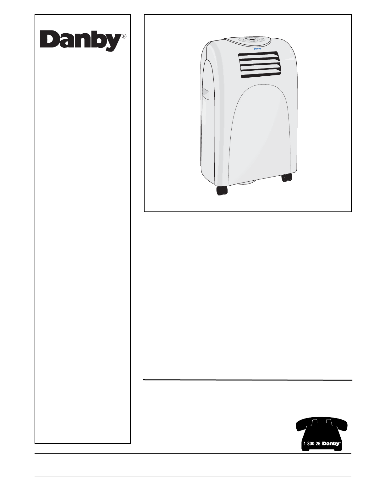
PORTABLE AIR CONDITIONER
Table of contents . . . . . . . . . . . . . . . . . . . . . . 1
CLIMATISEUR PORTATIF
Table des matières . . . . . . . . . . . . . . . . . . . . 15
Danby Products Ltd, PO Box 1778, Guelph, Ontario Canada N1H 6Z9
Danby Products Inc, PO Box 669, Findlay, Ohio USA 45839-0669
Version 1.11.07.
SAVE THESE INSTRUCTIONS!
SAUVEGARDER CES INSTRUCTIONS!
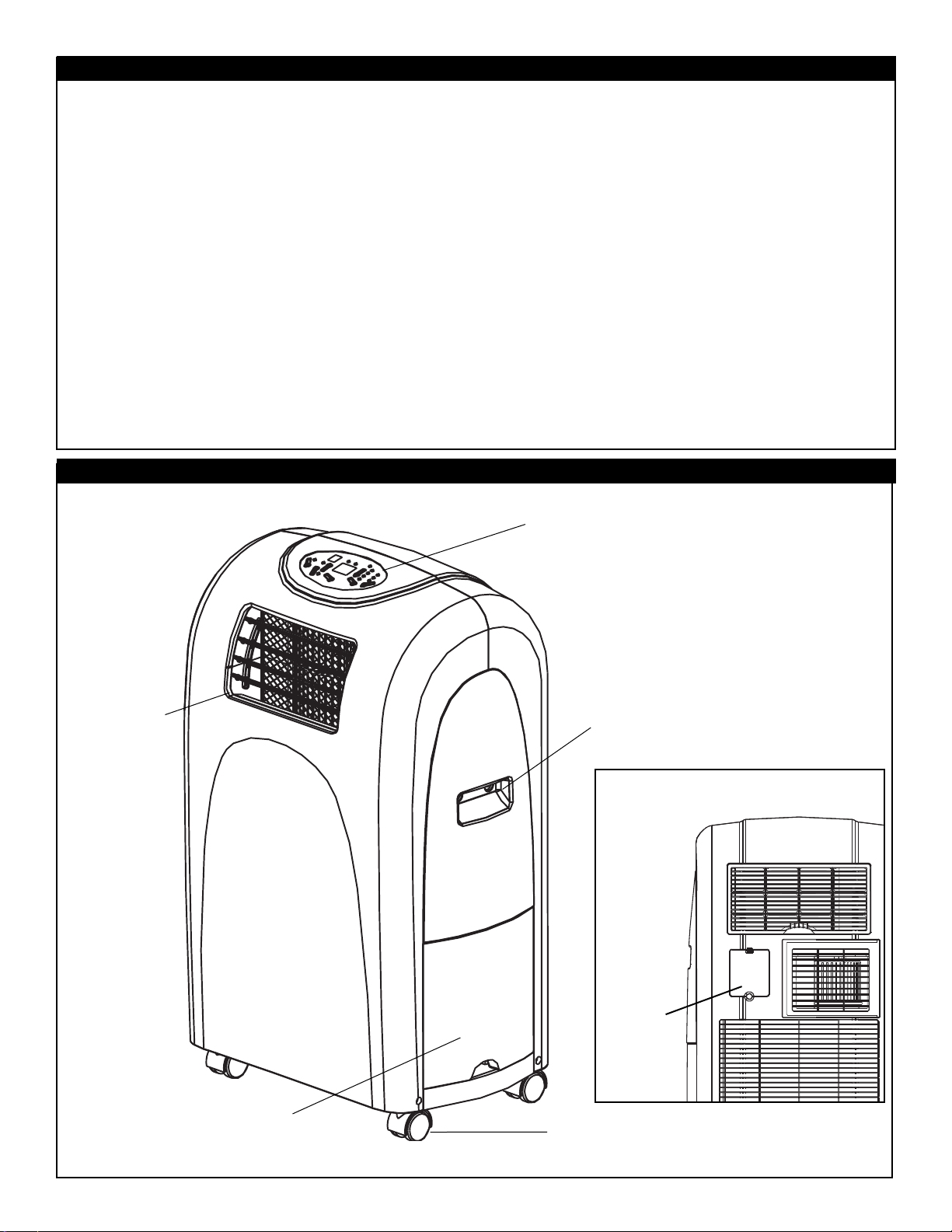
Table Of Contents
Introduction and Unit Specifications . . . . . . . . . . . . . . . . . . . . . . . . . . . . . . . . . 2
Electrical and Important Safety Information . . . . . . . . . . . . . . . . . . . . . . . . . . . 3
Energy-Saving Tips and Installation Accessories. . . . . . . . . . . . . . . . . . . . . . . 4
Direct Drain Instructions . . . . . . . . . . . . . . . . . . . . . . . . . . . . . . . . . . . . . . . . . . 5
Window Kit Installation . . . . . . . . . . . . . . . . . . . . . . . . . . . . . . . . . . . . . . . . . . . 6
Operating Instructions
Features of the Control Panel. . . . . . . . . . . . . . . . . . . . . . . . . . . . . . . . . . . . . . 7
• Air Conditioning . . . . . . . . . . . . . . . . . . . . . . . . . . . . . . . . . . . . . . . . . . . . . . . 8
• Fan Only & Dehumidifier . . . . . . . . . . . . . . . . . . . . . . . . . . . . . . . . . . . . . . . . 9
• Auto-Timer . . . . . . . . . . . . . . . . . . . . . . . . . . . . . . . . . . . . . . . . . . . . . . . . . . . 10-11
Care and Maintenance . . . . . . . . . . . . . . . . . . . . . . . . . . . . . . . . . . . . . . . . . . . 12
Warranty . . . . . . . . . . . . . . . . . . . . . . . . . . . . . . . . . . . . . . . . . . . . . . . . . . . . . . 13
Unit Parts Identification
Horizontal
Louver Blades
Carrying Handle
(both sides)
Easy-roll Castors
Control Panel
1
Power
Cord
Storage
Removable
Water Tank
Air Filter
Cover

Introduction
Thank you for choosing a Danby appliance to provide you and your family with all of the “Home Comfort”
requirements for your home, cottage or office. This Owner’s Manual will provide you with valuable information
necessary for the proper care and maintenance of your new appliance. If properly maintained, your Danby
appliance will give you many years of trouble free operation. Please take a few moments and read the
instructions thoroughly and familiarize yourself with all of the operational aspects of this appliance.
Your Danby Portable Air-Conditioner is a multi-function room air-exchanging, air-processing appliance,
designed to offer you the functions of Air Conditioning, Dehumidifying and Independent Fan. This unit can be
conveniently moved from room to room within your home and set-up in just minutes. Imagine the convenience of Portable Home Comfort at your fingertips, anytime, anywhere.
For easy reference, may we suggest you attach a copy of your sales slip/receipt to this page, along with the
following information which is located on the manufacturers nameplate located on the rear panel of the unit.
Model Number: DPAC7008
Serial Number: ___________________________________________________
Date of Purchase: _________________________________________________
Dealer’s Name and Address: ________________________________________
This information will be required if your unit requires servicing and/or for general inquiries. To contact a
Customer Service Representative, call Danby TOLL FREE.
1-800-26-DANBY
2
NOTE:
Continuing research results in steady improvement. Therefore, this information and these specifications are subject to change without notice.
Unit Specifications
Model Number DPAC7008
Cooling Capacity 7000 Btu/h
Noise Level 54 dB
Fan Speeds 3
Airflow CFM High / Medium / Low 280 / 240 / 210
Power Source 115 V / 60 Hz
Refrigerant R22
Internal Reservoir Capacity 3 Liters (6.3 Pints)
Unit Weight 28 kg (61.73 lb.)
Unit Dimensions (inches) W x D x H 17-2/16" x 13-3/16" x 29”
Unit Dimensions (mm) W x D x H 435 x 335 x 737
Remote Control Ye s
Time of Day Clock No
Auto - Timer Ye s
The power cord supplied with this air conditioner
contains a current leakage detection device
designed to reduce the risk of fire. Please refer to
the section "Power Supply Cord" for details. In the
event the power supply cord is damaged, it cannot
be repaired it must be replaced with a new cord
from the Product Manufacturer.
• Under no circumstances should this device be
used to turn the air conditioner on or off.
• The ‘RESET’ button must always be pushed in
(engaged) for correct operation.
• The power supply cord must be replaced if it fails
to reset when the ‘TEST’ button is pushed in.
• If the power supply cord is damaged, it cannot
be repaired. It must be replaced with a new cord
obtained from the Product Manufacturer.
Important Safety Instructions
Electrical Specifications
1. Check available power supply and resolve any
wiring problems BEFORE installation and operation of this unit. All wiring must comply with local
and national electrical codes and be installed by
a qualified electrician. If you have any questions
regarding the following instructions, contact a
qualified electrician.
2. This appliance draws 6.5 nameplate amps under
Cooling Mode and may be used in any properly
wired, general purpose 15 amp household
grounded receptacle.
3. For your safety and protection, this unit is
grounded through the power cord plug when
plugged into a matching wall outlet. If you are
not sure whether the wall outlets in your home
are properly grounded, please consult a qualified
electrician.
4. DO NOT USE PLUG ADAPTERS OR REGULAR
EXTENSION CORDS WITH THIS UNIT. If it is
necessary to use an extension cord with this
unit, use an approved “air conditioner” extension
cord only (available at most hardware stores).
5. To avoid the possibility of personal injury, always
disconnect the power supply to the unit, before
installing and/or servicing.
Table 1
Suggested Individual Branch Circuit
Nameplate Amps AWG Wire Size*
6.5 14
AWG- American Wire Gage
* Based on copper wire at 60°C temperature rating.
Table 2
Receptacle and Fuse Types
Rated Volts 125
Amps 15
Wall Outlet
Fuse Size 15
Time Delay Fuse Plug Type
(or circuit breaker)
Tf
The power cord supplied with this air conditioner
contains a device that senses damage to the power
cord. To test if your power supply cord is working
properly, you must do the following;
1. Connect the power supply cord to an electrical
outlet.
2. The power supply cord is inclusive of two buttons
located on the head of the plug. One button is
marked ‘TEST’, the other button is marked
‘RESET’. Press the ‘TEST’ button, you will hear a
click as the ‘RESET’ button pops out.
3. Press the ‘RESET’ button, you will hear a click as
the button engages.
4. The power supply cord is now energized and
supplying electricity to the air conditioner. (On
some products this is also indicated by a light on
the plug head).
CAUTION
Do not leave this unit unattended in a space
where people or animals who cannot react to a
failed unit are located. A failed unit can cause
extreme overheating or death in such an
enclosed, unattended space.
3
Power Supply Cord
WARNING!:Improper connection of the ground-
ing plug can result in a risk of;
Fire, Electric
Shock and/or Injury to Persons associated with
the Appliance.
Check with a qualified electrician
or service representative if you are in doubt that
the appliance is properly grounded.
Accessories
Installation Accessories
Fig. 1
Description Quantity
Flexible exhaust hose, collar & adapter .....1/set
f
Adjustable window door slider kit .............1/set
from 22 9/16" (67.5 cm) up to 48 7/16" (123 cm)
Direct Drain Adapter (not shown) ..............1 pc.
• The garden hose for elongated direct drain appli-
cations is not included
with this unit.
NOTE: The exhaust window kit must be installed at
all times when the unit is operating under the AIR
CONDITIONING mode.
4
CAUTION
To avoid installation/operation difficulties,
read these instructions thoroughly.
Electric Shock Hazard
To avoid the possibility of personal
injury, disconnect power to the unit
before installing or servicing.
Energy-Saving Tips
Your Danby appliance is designed to be highly
efficient in energy savings. Follow these recom-
mendations for greater efficiency:
1) Select a thermostat setting that suits your comfort needs and leave at that chosen setting.
2) The air filter is very efficient in removing airborne
particles. Keep the air filter clean at all times.
3) Use drapes, curtains or shades to keep direct
sunlight from penetrating and heating room, but
do not allow drapes or curtains to obstruct the
air flow around the unit.
4) Start your air conditioner before the outdoor air
becomes hot and uncomfortable. This avoids an
initial period of discomfort while the unit is cooling off the room. Use of the automatic start/stop
programmable TIMER feature can be a major
asset in this regard if utilized to the fullest extent.
5) When outdoor temperatures are cool enough,
turn the air conditioner off and use the FAN
MODE on HIGH, MEDIUM or LOW. This circulates indoor air, providing some cooling comfort
and utilizes less electricity.
Window Exhaust
Adapter
Adjustable Window Slider Kit
22 9/16" (67.5 cm)~ 48 7/16" (123 cm)
Flexible Exhaust Hose
Fig. 1 Installation Accessories
Adapter
IMPORTANT
There should be at least 11.8" (30 cm) clearance
between the unit and any other objects or building
structure and should be installed on a level surface. The unit does not have to be vented outside
during Dehumidifer or Fan Only mode operation.
Hose
Collar
Direct Drain Instructions
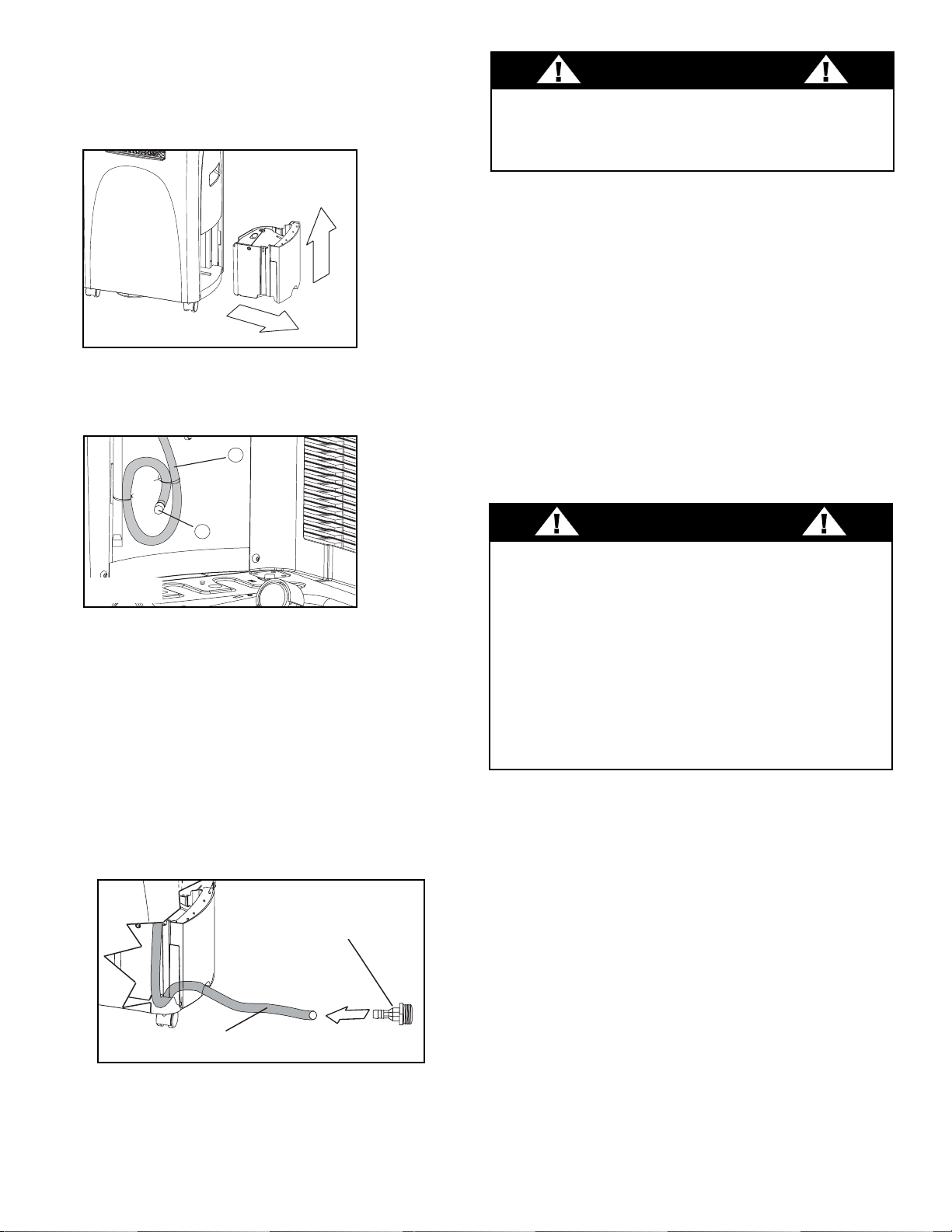
1. Remove the internal water tank; gently lift then
pull outward as shown in Figure 2.
2. Locate the direct drain hose Figure 3 (a), and
proceed to remove the black plug located at the
end of the hose Figure 3 (b).
3. Route the end of the hose under the side of the
water tank, then through the hole provided on
the face of the tank and place the water tank
back into the cabinet (As shown in Figure 4).
If
required
, attach the included drain hose adapter
(Fig 4) to the end of the drain tube and attach a
section of garden hose (not included) to suit
your continuous drain option requirements.
Important:
Ensure that the drain hose section
does not interfere with the correct positioning of
the water tank inside the cabinet.
Please Note: Remember to reverse the above
direct drain instructions when relocating the unit to
a location where continuous drain is not possible.
Failure to replace and recap the direct drain hose
may resulting in flooding of the immediate area.
a
b
Fig.3
1
2
Fig.2
Fig.4
Water Tank Safety Feature
This unit is equipped with a fail-safe switch mechanism which prevents the unit from condensing water
in the event the internal water tank is accidentally
displaced and/or is full. If this situation occurs, the
(RED) WATER FULL indicator light will illuminate.
This condition will remain steady until the external
water tank is emptied.
NOTE: No cooling will occur until the internal
tank is emptied and/or re-positioned. It may take
several minutes before the compressor resumes
normal operation.
CAUTION
During air conditioning and dehumidifier mode, if the
compressor cycle is interrupted (water full condition,
unplugged, power failure,etc.) and reinstated immediately thereafter, (within 3-5 minutes) a “compressor
protection circuit” is automatically activated. The
compressor cannot operate during “compressor protection” mode. (this is normal) It may take 3-5 minutes before the “protection circuit” self-deactivates.
DO NOT ATTEMPT TO START THE UNIT (COM-
PRESSOR) DURING THIS PERIOD.
5
CAUTION
Always empty the external water tank before
attempting to move or re-locate the unit to another
location.
Direct Drain
Adapter
Direct Drain Tube
CF
KEY PAD FUNCTIONS
Cool Mode:
Illuminates while the unit
is operating in air conditioning mode.
Fan Only Mode:
Illuminates while unit
is operating in ‘Fan Only’ mode.
Dehumidifier (Dry) Mode:
Illuminates
while the unit is operating in dehumidification mode.
MODE INDICATOR LIGHTS
STATUS DISPLAY
Low Fan
Medium Fan
FAN SPEED INDICATOR LIGHTS
High Fan
AUTO-ON: Signifies the auto-ontimer
setting has been initiated.
Water Full: Illuminates to indicate that
the inter water tank is full and will have
to be emptied.
TEMPERATURE DISPLAY: Displays
current ambient room (fan mode only)
or set temperature in Celsius or
Fahrenheit scale.
Celsius: Signifies
the temperature is
current;y displayed in Celsius.
Fahrenheit:
Signifies the temperature
is currently displayed in Fahrenheit.
AUTO-OFF: Signifies the auto-
off
timer
setting has been initiated.
POWER SWITCH: Turns unit On /
MODE : Allows you to scroll through
and select the desired operating
mode.
FAN : Select from three different fan
settings;
High Medium and Low.
AUTO-TIMER Adjust :
TIMER-ON: Used to initiate the AUTOON (start) timer and adjust Timer On
settings
forward
(0.5 hour increments).
TIMER-OFF: Used to initiate the
AUTO-OFF (stop) timer and adjust
Timer Off settings
forward
(0.5 hour
TEMPERATURE Adjust:
Continually depress to adjust temperature settings forward (1°C / °F increments).
Continually depress to adjust temperature settings
backward
(1°C / °F incre-
ments).
Note
: This appliance allows you to select the tem-
perature scale to be displayed in either the “Celsius”
or Fahrenheit” according to your preference.
To change temperature scale displayed on the control panel display, press and hold and arrow
buttons simultaneously to alternate between the
“Celsius” & “Fahrenheit” scale.
7
MODE
C
F
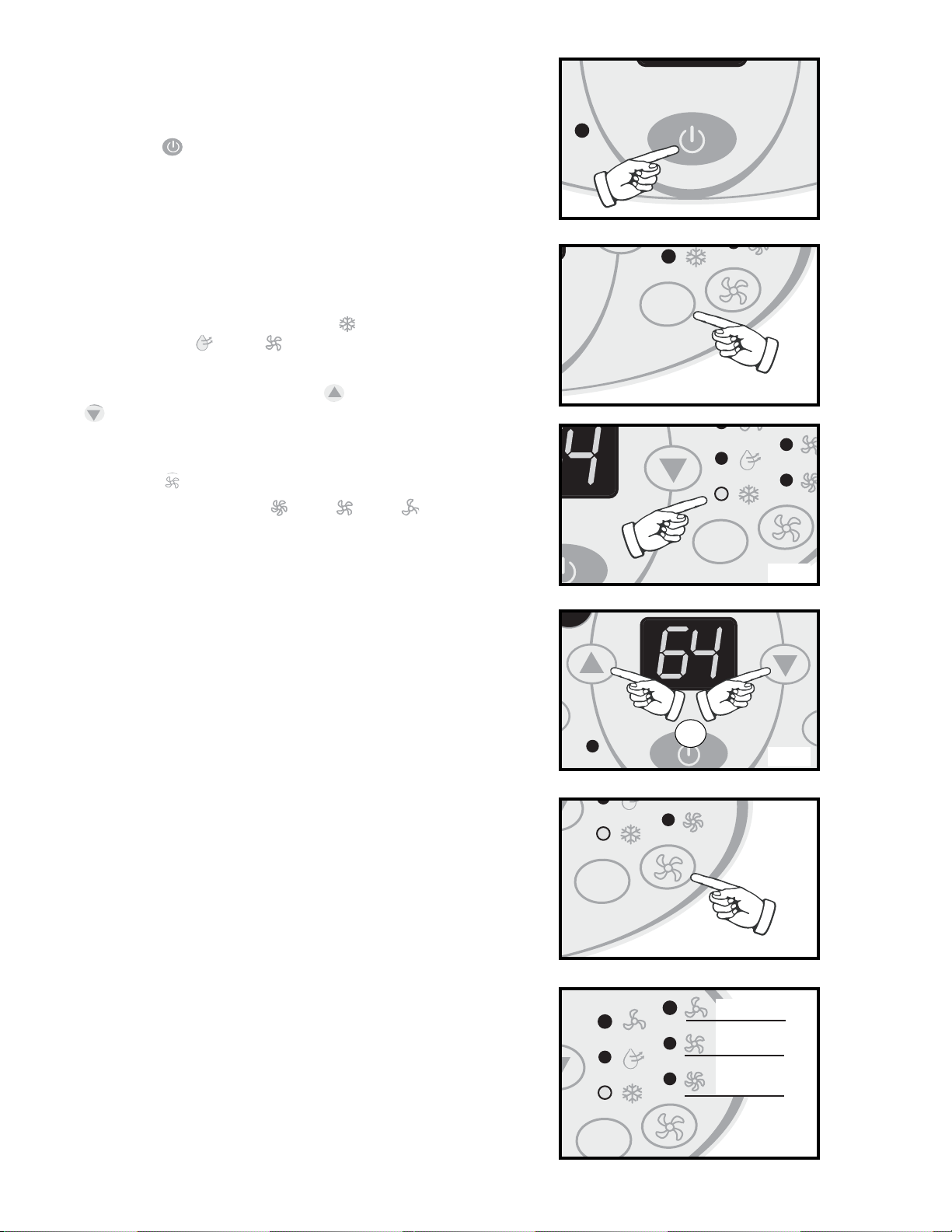
Air Conditioning Operating Instructions:
IMPORTANT: The exhaust hose must be properly
vented (outdoors) during air conditioning mode.
1) Press the POWER SWITCH key
Fig A
to
switch on the unit, and the
previous set tempera-
ture
will be shown in the temperature display
area of the control panel.
2) Press the MODE key
Fig B.
until the COOL indi-
cator light illuminates on the control panel
Fig C.
Each depression of the MODE key will advance
to a different mode setting (Cool -
Dehumidifier - Fan ).
3) Press the appropriate increase or decrease
buttons
Fig D
to select a suitable operating
temperature setting. Temperature settings are
adjustable between 17°C (62.6°F) ~ 30°C (86°F ).
4) Press the FAN key
Fig E
to select the desired
fan speed setting (High -Med -Low ).
Your selection will appear on the control panel
(each depression of the fan key will advance to a
different setting).
• Cooling stops automatically when the set
temperature is achieved. Cooling
resumes when the room temperature
rises above the “set” temperature level.
8
M
Fig F
Fig B
Fig A
Fig D
Fig E
Fig C
or
MODE
MODE
MODE
Low
Medium
High
MODE
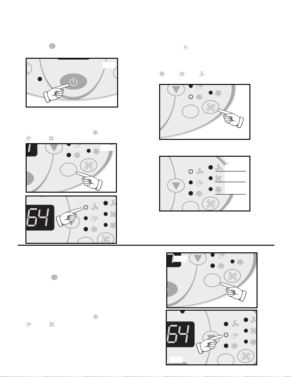
Fan Operating Instructions:
Note: During Fan mode, the exhaust hose does
not have to be vented outdoors.
1) Press the (on/off) key pad to switch on the
unit.
Fig G
2) Press the MODE key
Fig H
until the FAN indica-
tor illuminates on the control panel
Fig I
. Each
depression of the MODE key will advance to a
different mode setting (Cool -Dehumidifier
- Fan ).
3) Press the FAN key Fig J to select the desired
FAN SPEED setting. Your selection will appear
on the control panel. Each depression of the fan
key will advance to a different fan speed (High
-Med -Low ) as shown in Fig K.
M
Fig G
Fig H
CF
Fig M
Dehumidifier Operating Instructions:
Note: During dehumidifier mode, the exhaust
hose does not have to be vented outdoors.
1)
Press the (on/off) key pad to switch on the
unit.
Fig G
2) Press the MODE key
Fig L
until the DRY indica-
tor illuminates on the control panel
Fig M
. Each
depression of the MODE key will advance to a
different mode setting (Cool -Dehumidifier
- Fan ).
•
Important
: There is no fan speed or temperature
adjustment during dehumidifier mode. The fan
speed is factory set for ‘High’ and the dehumidifier
operates continuously (non-stop) regardless of
ambient humidity level or set temperature.
Fig J
Fig K
Fig L
CF
9
MODE
MODE
Low
Medium
High
MODE
MODE
MODE

Auto-Timer Instructions:
The AUTO-TIMER feature offers a unique selection
of multiple choice, fully automatic on and/or off
(start/stop) programs between 0.5 - 24 hrs under
any one mode of your Home Comfort unit.
The programs are as follows:
a) Auto -Off: Pre-select a time that will turn off the
unit automatically (between 0.5 - 24 hrs.).
b) Auto-On: Pre-select a time that will turn on the
unit automatically (between 0.5 - 24 hrs.).
c) Auto-On & Auto-Off:Pre-select a time that will
turn the unit ON / OFF (automatically) at specified times (between 0.5 - 24 hrs).
Note: These functions must be performed daily, as
the program is automatically canceled/erased after
the program has ended .
Setting the AUTO-OFF TIMER
Before setting the AUTO-OFF timer, the unit must
be (operational) turned on.
1) Press the TIMER-OFF key pad (
Fig N)
to ini-
tiate the AUTO-OFF time sequence. The “AUTO-
OFF” indicator (
Fig O)
will illuminate on the con-
trol panel and the timer digits (
Fig P)
will appear.
2)
Continually depress
the
keyto adjust Timer-Off
settings
forward
by 0.5 hour increments
(between
0.5 - 24 hrs)
.
3) The timer setting will remain in the display window for three seconds before automatically
reverting back to the temperature display.
4) To view the timer setting at any time; press the
TIMER-OFF key pad again and the timer
length you selected will be shown in the display
window.
• The unit will stop automatically at the specified
AUTO-OFF set time.
• NOTE: To cancel or override the AUTO-OFF
program, press the TIMER-OFF key t
o adjust
Timer-Off settings
forward
to 0.0 hours
.
10
D
MO

Setting the AUTO-ON TIMER
You must select all appropriate settings required to
operate under the AUTO TIMED program before ini-
tiating the AUTO-ON program;
• Select the appropriate MODE under which
you want the unit to operate (Cool,
Dehumidify or Fan).
• Select the appropriate FAN SPEED set-
ting, under which you want the unit to
operate; Hi, Medium or Low. (excluding
Dehumidifying, as this mode has one
(1) pre-set fan speed setting only).
• To set the AUTO-ON timer, the unit must
be turned “off” (non-operational).
1) Press the (on/off) key pad to switch on the
unit.
Fig S
2) Select all appropriate operational settings (see
listing above).
3) Press the (on/off) key pad to switch the unit
off.
Fig S
4) Press the TIMER-ON key pad (
Fig T)
to initi-
ate the AUTO-ON time sequence. The “AUTO-
ON” indicator light (
Fig U)
will illuminate on the
control panel and the timer digits (
Fig V)
will
appear in the display window.
5)
Continually depress the key
t
o adjust Timer On
settings
forward
by 0.5 hour increments (0.5 ~ 24
hours).
6) To view the timer setting at any time; press the
TIMER-OFF key pad again and the timer
length you selected will be shown in the display
window.
• The unit will start automatically at the specified
AUTO-ON set time.
• To cancel or override the AUTO-ON program,
simply turn on the unit anytime prior to when the
AUTO-ON time is scheduled to operate.
Setting the AUTO-ON & OFF timer
Follow the above steps to set the auto-on timer then
proceed to set the auto-off timer (see page 11).
When setting the auto-on and auto off timer, the
operation (running) time of the unit is the difference
between the auto-on and auto-off set timer lengths.
For example,to have the unit automatically power on
two hours from now, then operate for one hour and
power off; Set the auto-on timer length to 2 hours,
and set the auto-off timer length to 3 hours, this sets
the timer program for 1 hour of operation.
11
O
M

Remote Control Instructions
Control Buttons
1) Power Switch
2) Mode
3) Fan Speed
4) Used to increase or decrease the temperature to
select a suitable operating temperature setting.
5) Lock: Prevents the remote control settings from
being inadvertently being changed.
6) Restore remote control default settings.
7) TIMER-ON: Used to initiate the AUTO-ON (start)
timer and adjust Timer On settings
forward
(0.5/1h)
8) TIMER-OFF: Used to initiate the AUTO-OFF
(stop) timer and adjust Timer Off settings
forward
(0.5/1h)
To operate the hand held remote control will require
two “AAA” Alkaline batteries (included).
Batteries should be replaced when:
a) No signal (beep) is heard when attempting to
program the main unit.
b) The main unit does not respond to a command
issued by the remote.
Battery replacement:
1. Slide the rear cover on the remote in the general
direction of the arrow. Continue pulling (gently) until
the cover seperates completely from the unit.
2. Insert (2) batteries (AAA) following the same orientation (polarity) depicted inside the battery chamber (+/-).
3. Re-install rear cover.
4. If the remote control will not be used for extended periods of time (vacations, etc.), batteries should
be removed.
The remote operates within a range of 8 meters
(26 ft.) from the receiver located inside the main
unit. Any obstruction between the receiver and
remote may cause signal interference, limiting the
ability to program the main unit.
Note:
• Remote sets/shows °C only.
TEMP.(°C)
1
2
3
4
5
6
7
Electronic
Display

12
Care and Maintenance
1) Do Not use gasoline, benzene, thinner or any
other chemicals to clean this unit ,as these substances may cause damage to the finish and
deformation of plastic parts.
2) Never attempt to clean the unit by pouring water
directly over any of the surface areas, as this will
cause deterioration of electrical components and
wiring insulation.
Storage and End of Season Care
If the unit will not be in use for a long period oftime
or is to be stored.
1. Remove the water tank and place a trip tray
beneath sump drain tube Fig 7 (c).
2. Remove the black plug Fig 7 (d) to manually
release the water from the internal reservoir.
CAUTION: Failure to replace and recap the
direct sump drain tube prior to using the unit
may resulting in flooding of the immediate area.
Removal and Cleaning of the Air Filter
If the air filter becomes clogged with dust/dirt, air
flow is restricted and reduces cooling efficiency.
The air filter should be cleaned every two (2) weeks.
More frequent cleaning may be necessary depending upon indoor air quality. NOTE: The air filter is
located at the (upper) rear side of the unit.
1) To remove the air filter: Pull the air filter cover
upward in the direction of the arrow
Fig 8
and
remove the air filter.
2) Dust/Dirt clogged in the filter can be removed by
vacuum cleaning the soiled areas.
4) The filter can also be washed in lukewarm soapy
water while rubbing it lightly with a brush. A mild
detergent (dishwashing soap) is recommended.
5) Rinse the filter well using clean water. Allow
time to dry before reinstalling into the unit.
6) Replace the air filter and cover.
7) Replacement air filter information is available
by the Customer Service Department at:
1-800-26-DANBY (1-800-263-2629)
CAUTION
Never operate the unit without the air filter in
place as this may result in damage to the unit.
CAUTION
Before cleaning or servicing this unit, it is recommended that the unit be disconnected from any
electrical supply outlet.
Fig.7
c
d
LIMITED AIR CONDITIONER WARRANTY
This quality product is warranted to be free from manufacturer’s defects in material and workmanship, provided that the unit is used under the normal operating
conditions intended by the manufacturer.
This warranty is available only to the person to whom the unit was originally sold by Danby or by an authorized distributor of Danby, and is non-transferable.
TERMS OF WARRANTY
Plastic parts, are warranted for thirty (30) days only from purchase date, with no extensions provided.
First 12 Months
During the first twelve (12) months, any electrical parts of this product found to be defective, including any sealed system units, will be
repaired or replaced, at warrantor’s option, at no charge to the ORIGINAL purchaser.
To obtain
Danby reserves the right to limit the boundaries of “In Home Service” to the proximity of an Authorized Service Depot. Any appliance
Service
requiring service outside the limited boundaries of “In Home Service” ,
it will be the consumer’s responsibility to transport the appliance
(at their own expense) to the original retailer (point of purchase) or a service depot for repair. Contact your dealer from whom your unit
was purchased, or contact your nearest authorized Danby service depot, where service must be performed by a qualified service technician.
If service is performed on the units by anyone other than an authorized service depot, or the unit is used for commercial application, all
obligations of Danby under this warranty shall be at an end.
EXCLUSIONS
Save as herein provided, Danby Products Limited (Canada) or Danby Products Inc. (U.S.A.), there are no other warranties, conditions, representations or guarantees, express or implied, made or intended by Danby Products Limited or its authorized distributors and all other warranties, conditions, representations or guarantees, including any warranties, conditions, representations or guarantees under any Sale of Goods Act or like legislation or statue is hereby expressly excluded. Save as herein provided, Danby Products Limited (Canada) or Danby Products Inc. (U.S.A), shall not be responsible for any damages to persons or property,
including the unit itself, howsoever caused or any consequential damages arising from the malfunction of the unit and by the purchase of the unit, the purchaser
does hereby agree to indemnify and save harmless Danby Products Limited from any claim for damages to persons or property caused by the unit.
GENERAL PROVISIONS
No warranty or insurance herein contained or set out shall apply when damage or repair is caused by any of the following:
1) Power Failure.
2) Damage in transit or when moving the appliance.
3) Improper power supply such as low voltage, defective house wiring or inadequate fuses.
4) Accident, alteration, abuse or misuse of the appliance such as inadequate air circulation in the room or abnormal operating conditions,
(extremely high or low room temperature).
5) Use for commercial or industrial purposes.
6) Fire, water damage, theft, war, riot, hostility, acts of God such as hurricanes, floods etc.
7) Service calls resulting in customer education.
Proof of purchase date will be required for warranty claims; so, please retain bills of sale. In the event warranty service is required, present this document to our
AUTHORIZED SERVICE DEPOT.
Danby Products Limited
PO Box 1778, 5070 Whitelaw RD, Guelph, Ontario, Canada N1H 6Z9
Telephone: (519) 837-0920 FAX: (519) 837-0449
Danby Products Inc.
PO Box 669, 101 Bentley Court, Findlay, Ohio, U.S.A. 45840
Telephone: (419) 425-8627 FAX: (419) 425-8629
12/06
Warranty Service
In-House

Table des matières
Introduction et spécifications de l’unité.............................................................. 15
Spécifications électric puis consignes de sécurité importante...........................
16
Conseils pour la conservation de l’énergie........................................................ 17
Instruction pour Drainage Direct .............................................................................. 18
Directives d’installation du kit de la fenêtre ....................................................... 19
Instructions de Fonctionnement
Caractéristiques de panneau de commande . . . . . . . . . . . . . . . . . . . . . . . . . . 20
• Climatiseur . . . . . . . . . . . . . . . . . . . . . . . . . . . . . . . . . . . . . . . . . . . . . . . . . . . 21
• Ventilateur Seulement / Déshumidificateur. . . . . . . . . . . . . . . . . . . . . . . . . . . 22
• Minutrie Automatique . . . . . . . . . . . . . . . . . . . . . . . . . . . . . . . . . . . . . . . . . . . 23-24
Soins et entretien............................................................................................... 25
Identification des pièces de l’appareil
Panneau du
filtre à air
Poignées
(aux deux côtés)
Roulettes pivotantes
Panneau de
commande
Cordon
D’Alimentation
14
Réservoir
d’eau

Caractéristiques de t
élé
commande
Boutons De Commande:
1) Commutateur de courant
2) Mode
3) Vitesse du ventilateur
4) Utilise pour augmenter la température.
5) Serrure empêche les arrangements de
télécommande d’être changé.
6) Reconstituez tous les arrangements de
télécommande au réglages par défaut.
7) Minutrie en March: Utilisée pour activer le
minutrie mise EN MARCHE-AUTO et pour régler
le minuterie en augmentant par incréments de
0.5/1heures.
8) Minuterie à L’Arrêt: Utilisée pour activer le
minutrie ARR
ÊT-AUTO et pour régler le minut-
erie
en augmentant par incréments de 0.5/1heures.
Deux piles alcalines «AAA» sont requises pour le
fonctionnement de la télécommande (incluses).
Les piles devraient être remplacées quand :
a) Aucun signal sonore (bip) n’est entendu durant
la
programmation de l’unité principale.
b) L’unité principale ne répond pas à un signal émis
par la télécommande.
Remplacement des piles :
1. Glisser le couvercle du compartiment des piles à
l’arrière de la télécommande dans le sens
de la flèche. Tirer délicatement
jusqu’à ce que le couvercle se
sépare complètement de l’unité.
2. Insérer deux (2) piles (AAA) en observant la
polarité indiquée dans le compartiment des piles
(+/-).
3. Réinstaller le couvercle.
4. Si la télécommande ne sera pas utilisée pour
des périodes prolongées (vacances, etc.), les
piles devraient étre retirées de la
télécommande.
La télécommande fonctionnera en dedans d’une
distance de 8 mètres (26 pi.) du récepteur situé à
l’intérieur de l’unité principale. Toute obstruction
entre le récepteur et la télécommande pourrait
causer une interférence au signal, ce qui limiterait la
capacité de programmation de l’unité principale.
Remarque :
• Le température est affiché sur l’affichage
électronique en échelle Celcius seulement.
TEMP.(°C)
1
2
3
4
5
6
7
Affichange
Électronique

Introduction
Merci d’avoir choisi un appareil Danby qui vous fournira ainsi qu’à votre famille, le confort au foyer, à la maison, au chalet ou au
bureau. Ce manuel d’utilisation vous offre des renseignements pratiques pour le soin et l’entretien de votre nouvel appareil. Un
appareil Danby bien entretenu vous fournira plusieurs années de service sans ennui.
Veuillez prendre quelques moments pour lire attentivement toutes les directives pour vous renseigner et vous familiariser avec
tous les aspects du fonctionnement de votre appareil.
Votre climatiseur portable Danby est un appareil d’échange et de traitement de l’air à mulit-fonctions. Sa conception vous offre
les fonctions suivantes: climatisation, déshumidification et la ventilation indépendante. Cet appareil peut être aisément déplacé
d’une pièce à l’autre de la maison et il est installé en quelques minutes seulement. Imaginez la commodité du confort au foyer à
portée de la main, en tout temps, en tout lieu.
Pour la référence aisée, nous vous suggérons de joindre une copie de votre reçu de caisse et/ou facture d’achat à cette page, et
d’inscrire les renseignements suivants qui sont trouvés sur la plaque d’identification du fabricant. Celle-ci est située sur le panneau arrière de l’appareil.
Numéro de modèle :
DPAC7008
Numéro de série :
___________________________________________________
Date d’achat :
______________________________________________________
Nom du marchand et adresse :
__________________________________________
Ces renseignements seront requis si le service est demandé et/ou si vous désirez obtenir des renseignements supplémentaires. Pour consulter un Représentant du service à la clientèle, composez le NUMÉRO D’APPEL SANS FRAIS suivant :
1-800-26-DANBY
Spécifications de l’unité DPAC7008
Capacité de climatisation 7000 BTU/h
Niveau de bruit 54 dB
Vitesses du ventilateur 3
CFM Haute / Moyenne / Basse 280 / 240 / 210
Source d’alimentation 115 V / 60 Hz
Réfrigérant R22
Contenance du réservoir d’eau interne 3,0L (6,3 Pintes)
Poids de l’unité 28 kg (61,73 lb.)
Dimensions de l’unité (pouces) lgr x pfdr x htr 17-2/16 x 13-3/16 x 29 po
Dimensions de l’unité (mm) lgr x pfdr x htr 435 x 335 x 737
Panneau de contrôle (illuminé) Touches de commandes
Télécommande Oui
Horloge Non
Minuterie automatique Oui
REMARQUE :
La recherche ensuit toujours des améliorations. Par conséquent, ces informations et spécifi-
cations peuvent changer sans préavis.
15

Spécifications électriques
1. Vérifier l’alimentation de courant disponible et résoudre
tout problème AVANT l’installation et l’usage de cette
unité. Le câblage doit être conforme aux codes local et
national de l’électricité avec l’installation par un élec-
tricien qualifié. Pour toutes questions concernant les
directives qui suivent, communiquer avec un
électricien qualifié.
2. Cet appareil débite 6.5 ampères tel qu’indiqué sur la
plaque d’identification en mode de refroidissement et il
peut être utilisé avec tout réceptacle domestique de 15
ampères d’usage général, correctement câblé et mis à la
terre.
3. Pour votre sécurité et votre protection, cette unité est
mise à la terre par la fiche du cordon d’alimentation
quand elle est branchée sur une prise de courant
adaptée. Si vous n’êtes pas certain que les prises de
courant de votre domicile sont correctement mises à la
terre, consultez un électricien qualifié.
4. NE PAS UTILISER LES ADAPTATEURS DE FICHE OU
LES CORDES DE RALLONGE AVEC CETTE
UNITÉ. S’il est nécessaire d’en utiliser
une, utiliser une corde de rallonge approuvée pour l’usage avec les climatiseurs
seulement (disponible dans la plupart des quincailleries
locales).
5. Pour éviter la possibilité de blessure corporelle, toujours
débrancher l’alimentation de courant à l’unité avant
Tableau 1
Circuit de distribution individuel suggéré
Ampères de plaque d’identification Calibre de fil AWG*
6.5 14
AWG – American Wire Gauge (Calibre de fil américain)
*Basé sur le fil en cuivre à une température nominale de 600C
Tableau 2
Types de fusibles et de réceptacles
Tension nominale 125
Ampères 15
Prise de courant
Intensité de fusible 15
Fusible temporisé Type fiche
(ou disjoncteur de circuit)
16
MISE EN GARDE
Ne jamais laisser cet appareil en marche dans un endroit
fermé où des personnes ou animaux qui ne peuvent pas
réagir à une défectuosité de l’appareil se trouvent. Un
appareil en panne peut occasionner la surchauffe extrême
de cet appareil ou la mort dans un espace fermé non surveillé.
Le cordon d'alimentation fourni avec ce climatiseur
est doté d'un système de détection de dommages.
Afin de vérifier si votre cordon d'alimentation fonctionne bien, procédez comme suit :
1. Branchez le cordon d'alimentation à une prise
électrique.
2. Le cordon d'alimentation est doté de deux
boutons à la tête de la fiche. Il s'agit des boutons
"TEST " et " RESET ". Lorsque vous enfoncez le
bouton " TEST ", un clic se fait entendre et le
bouton " RESET " ressort.
3. Lorsque vous enfoncez le bouton " RESET ", un
clic se fait entendre.
4. Le cordon d'alimentation est maintenant chargé et
en mesure d'alimenter le climatiseur. (Sur cer-
tains produits, cet état est indiqué à l'aide d'un témoin
sur la tête de la fiche)
Cordon d'alimentation
Le cordon d'alimentation fourni avec ce climatiseur
est doté d'un système de détection de fuite destiné
à diminuer les risques d'incendie. Veuillez consulter
la section " Cordon d'alimentation " pour plus de
détails. Si le cordon d'alimentation est endommagé,
il ne peut être réparé et doit être remplacé par un
nouveau cordon du manufacturier.
• En aucun cas cet appareil ne doit-il être utilisé
pour allumer ou éteindre le conditionneur.
• Le bouton " RESET " doit toujours être enfoncé
pour un bon fonctionnement.
• Le cordon d'alimentation doit être remplacé s'il
ne se réinitialise plus lorsque le bouton " TEST " est
enfoncé.
• Si le cordon d'alimentation est endommagé, il
doit être réparé. Il doit être remplacé par un
nouveau cordon du manufacturier.
Consignes de sécurité importantes
AVERTISSEMENT!:
Une connexion inadéquate de
la mise à la terre de la fiche peut causer les
risques; D'incendie, Chocs électriques et/ou De
blessures corporellesConsultez un électricien
qualifié ou un représentant du service si vous n'êtes
pas certain de la mise à la terre de l'appareil.

Installation dans la fenêtre
18
Fig. 1 Accessoires d’installation
Installation dans la fenêtre
Accessoires d’installation
Fig. 1
Description Quantité
Tuyau flexible pour l’échappement d’air
avec col de boyeau et adaptateurs ............1/ens.
Kit de coulisse de fenêtre ..........................1/ens.
de 22-9/16 po (67.5 cm) à 48 7/16 po (123 cm)
Raccord de Tuyau D’échappement .................1 pièce
(
non illustré
)
• Le tuyau de jardinage n’est pas inclus avec l’ap-
pareil.
REMARQUE SPÉCIALE : Le kit d’échappement
de fenêtre doit être installé en tout temps quand
l’unité fonctionne en mode de CLIMATISATION.
17
AVERTISSEMENT
Un dégagement minimal de 11,8 po (30 cm) entre
l’unité et tous autres objets ou structure est
nécessaire et devrait être installé sur une surface
de niveau. L'unité ne doit pas être exhalée dehors
pendant l'opération de mode ‘Sec’ ou
‘Ventilateur’, il est recommandée cependant que
les tuyaux restent installés (sur l'unité) pendant la
déshumidification.
Suggestions pour l’économie de l’énergie
Votre appareil ménager Danby est conçu pour l’efficacité
en économie de l’énergie. Pour le rendement maximal,
observer les recommandations qui suivent.
1. Choisir un réglage du thermostat qui répond à vos besoins
de confort et le laisser au réglage choisi.
2. Le filtre à air est très efficace pour éliminer les particules qui
flottent dans l’air. Conserver le filtre à air propre en tout temps.
3. Utiliser des draperies, des rideaux ou des stores pour
prévenir la pénétration et le réchauffement de la pièce
par les rayons directs du soleil, mais ne
pas permettre la restriction de la circulation
d’air autour de l’unité par les draperies ou les
rideaux.
4. Activer votre climatiseur avant que la température de l’air
extérieur ne soit très chaude et inconfortable. Ceci préviendra
une période initiale d’inconfort avant que l’unité ne puisse
refroidir la pièce. L’usage de la caractéristique de
MINUTERIE programmable d’arrêt et de mise en marche
automatique représente un important avantage à cet effet si
elle est utilisée à pleine capacité.
5. Quand les températures externes sont suffisamment froides,
placer le climatiseur hors de service et utiliser le MODE DE
VENTILATEUR à la position HAUTE, MOYENNE ou
BASSE . Ceci fait circuler l’air à l’intérieur de la pièce pour
fournir un certain confort de climatisation en utilisant moins
d’électricité.
MISE EN GARDE
Pour éviter les difficultés durant l’installation
et/ou le fonctionnement, lire ces directives
attentivement.
Risque de choc électrique
Pour éviter la possibilité de blessures
corporelles, débrancher l’alimentation
de courant à l’unité avant d’entreprendre
l’installation ou le service.
Tuyau flexible pour l’échappe-
ment d’air
Fig. 1 Accessoires d’installation
Adaptateur

18
MISE EN GARDE
Toujours vider le réservoirs d’eau externe avant de tenter de
déplacer ou de relocaliser l’unité dans un autre endroit.
Caractéristique de sécurité du réservoir d’eau
interne
Cette unité est equippée avec d’un mécanisme de
sûreé qui prévient la condensasition de l’eau dans
l’éventualité d’un déplacement accidentel du réservoir d’eau interne et/ou si le réservoir est plain.
Dans ce cas, l’
afficheur pour PLEIN D’EAU
(rouge)
s’illuminera. Cette condition demeurera jusqu’au
moment le résevoir d’eau est repositionné est/ou
vidé.
NOTE: Le moteur du ventilateur continuera de
fonctionner sous cette condition. Ceci est normal, mais aucune climatisation ne se produira
jusqu’à le résevoir d’eau est repositionné et/ou
vidé. Plusieurs minutes pourraient s’écouler
avant que le compresseur ne résume la fonctionnement normal.
MISE EN GARDE
En mode de climatisation et
déshumidification (Sec)
, si
le cycle du compresseur est interrompu (par plein
d’eau, le débranchement de l’unité ou par une
panne de courant, etc.) et immédiatement rétabli par
la suite, (en dedans de 3 à 5 minutes) un circuit de
protection du compresseur est automatiquement
activé. Le compresseur ne fonctionnera pas en
mode de protection. Ceci est normal et un délai de
3 à 5 minutes pourrait se produire avant que le cir-
cuit de protection du compresseur ne soit automa-
tiquement désactivé.
Instructions pour Drainage Direct
1. Enlevez le réservoir d'eau interne en soulevant
doucement le réservoir et tirez vers l'extérieur
comme représenté sur la Fig 2.
2. Trouvez le tuyau d’écoulement Fig 3 (a), et
procédez enlever la bouchon située à l'extrémité
du tuyau Fig. 3 (b).
3. Dirigez le bout du tuyau sous le côté du résevoir
d’eau, à travers le trou percé au devant du
réservoire, et puis replacez le résevoir d’eau
dans le caisson (Comme montré dans Fig. 4).
Important: Il faut s’assurer que le tuyau d’écoulement n’interfère pas au positionnement
approprié du résevoir d’eau dans le caisson.
Si nécessaire
, attachez le raccord du tuyau d’écoulement inclus (Fig 4) sur le bout du tuyau et
attachez une section du tuyau de jardinage (non
inclus) pour convenir à vos requirments de
drainage direct..
Remarque: Il faut se rappeler de renverser les
procédé ci-dessus lors du déplacement de l’appareil
à une autre location où l’option d’écoulement continu (drainage direct) est impossible. Défaut de
suivre ces procédés occasionnera une inondation.
a
b
Fig.3
1
2
Fig.2
Fig.4
raccord du tuyau
d’écoulement
tuyau d’écoulement

Installation du kit de fenêtre
(Mode Climatisation Seulement)
Votre kit de fenêtre a été conçu pour l’adaptation à
la plupart des fenêtres verticales et/ou horizontales
à une hauteur maximale de 48 7/16 po (123 cm).
Des positions à verrous sont prévues sur le rebord
de chaque section coulissante pour joindre ensemble chaque section coulissante.
1. Choisir un endroit approprié en vous assurant
d’avoir accès à une prise de courant.
2. Installer le tuyau flexible tuyau flexible pour
l’échappement d’air sur la partie arrière de l’unité.
Insérez le col du tuyau avec le adaptateur dans
l’ouverture et le pivoter pour le bloquer en position.
3. Installer le kit de coulisses réglables de fenêtre et/ou
de porte patio tel que requis.
Voir Fig. 5, 6. .
4. Installer l'extrémité opposée du tuyau flexible pour
l’échappement d’air sur l'adapteur d'échappement
de fenêtre.
5. Installer le adaptateur du tuyau flexible pour
l’échappement d’air dans l’ouverture de la section
coulissante, en vous assurant que la section coulissante est solidement fixée.
6.
Brancher l’unité dans une prise de courant de
115 volts / 60 Hz avec mise à la terre.
Fenêtre horizontale
Kit de coulisse de fenêtre
Minimum: 22 9/16 po (67.5
cm)
Fenêtre
verticale
19
Kit de coulisse de fenêtre
Minimum: 22 9/16 po (67.5 cm)
Maximum: 48 7/16 po (123 cm)

FONCTIONS DU BLOC DE TOUCHES
Mode Frais:
Illuminé quand l’appareil
fonctionne dans mode de climatiseur.
Ventilateur Seulement:
Illuminé
quand l’appareil fonctionne dans
mode de ventilateur.
Mode Déshumidificateurs:
Illuminé
quand l’appareil fonctionne dans
mode de
déshumidificateurs
.
INDICATEUR DE MODE
AFFICHAGE D'OPÉRATION
Caractéristiques
du panneau de
commande
Basse
Moyenne
INDICATEUR DE VITESSES DE VENTILATEUR
Haute
Minutrie en Marche: Illumine quand le
temps pour en marche-automatique est
défini.
Eau Plein: Indicateur s'illumine pour
indiquer que le réservoir d’eau externe
est plein et devra être vidé.
Température: Il montre la température
ambiante (mode de ventilateur seulement) ou la température réglée dans
Celcius ou Fahrenheit.
Ceclius: Signifie que la température est
montrée dans Celcius.
Fahrenheit: Signifie que la température
est montrée dans
Fahrenheit.
Minuterie
à L’Arrêt
: Illumine quand le
temps pour arrêt-automatique est
défini
INTERRUPTEUR: En Marche / Arrêt.
MODE : Vous permet de voir and
choisissez le mode d'opération
désiré.
VENTILATEUR : Choisissez trois
vitesses de ventilateur différentes;
Haut, Moyenne et Basse.
RÉGLAGE DE MINUTERIE:
Minutrie en Marche:
Utilisée pour activer
le minutrie mise EN MARCHE-AUTO. et
pour régler le minuterie en augmentant par
incréments de 0.5 heures.
Minuterie
à L’Arrêt:Utilisée pour activer
le minutrie
ARRÊT-
AUTO. et pour régler le
minuterie en augmentant par incréments de
0.5 heures.
RÉGLAGE DE TEMPÉRATURE:
Appuyez continuellement pour régler la
température en augmentant par incréments de 1
0
C / 10F .
Appuyez continuellement pour régler la
température en réduisant par incréments
de 1
0
C / 10F.
Note
:
Cet appareil ménager offre une caractéristique qui vous permettra l’option de régler les températures soit en degrés Celsius, soit Fahrenheit.
Pour changer l’affichage de la température sur l’unité principale, appuyer sur les touches.
et
simultanément pour alterner entre l’échelle C°et
F°.
20
CF
MODE
C
F

Directives d’utilisation du climatiseur :
REMARQUE : Le tuyau flexible pour l’échappement
d’air doivent être installés pour le fonctionnement en
mode de climatisation.
1. Appuyer sur la touche INTERRUPTEUR
Fig A
pour activer l’unité et le réglage précédent du température sera montrée dans l’affichage de la température sur le panneau de commande.
2. Appuyer sur la touche MODE
Fig B
jusqu’à l’indica-
teur du mode Frais illumine sur le panneau de
commande
Fig C
. Chaque dépression sur la touche
MODE avancera l’affichage à un réglage de mode
différent (Frais -
Sec
-Ventilateur ).
3. Appuyer sur le touche augmenter ou diminuer
(RÉGLAGE DE TEMPÉRATURE)
Fig D
pour
choisir un réglage de température appropriée. Les
réglages de température sont réglables entre 17°C
(62.6°F) à 30°C (86°F).
4. Appuyer sur la touche VENTILATEUR
Fig E
pour choisir le réglage de la vitesse désirée du ventilateur (Haute -Moyenne -Basse ). Votre
sélection apparaîtra sur le panneau de commande
(chaque dépression de la touche du ventilateur
avancera l’indicateur au prochain réglage).
• La climatisation cesse automatiquement quand
la température réglée est atteinte. La climatisation résume quand la température de la pièce
s’élève au-dessus de la température réglée.
21
M
MODE
MODE
MODE
Basse
Moyenne
Haute
MODE

Directives d’utilisation du ventilateur :
REMARQUE : L’installation du tuyau flexible pour
l’échappement d’air n’est pas requise pour le fonctionnement en mode de ventilation seulement.
1.Appuyer sur la touche INTERRUPTEUR pour
activer l’unité
Fig G
.
2.Appuyer sur la touche MODE
Fig H
jusqu’à l’af-
fichage du symbole Ventilateur sur le panneau de
commande
Fig I
. Chaque dépression sur la touche
MODE avancera l’affichage à un réglage de mode différent
(Frais -
Sec
-Ventilateur ).
3.Appuyer sur la touche VENTILATEUR
Fig J
pour
choisir la VITESSE DE VENTILATEUR désirée. Votre
réglage apparaîtra sur le panneau de commande
Fig
K
. Chaque dépression sur la touche VENTILATEUR
avancera l’affichage à un réglage de vitesse différente
(Haute -Moyenne -Basse ).
Directives d’utilisation
Déshumidificateur
:
REMARQUE : L’installation du tuyau flexible pour
l’échappement d’air n’est pas requise pour le fonctionnement en mode de
Déshumidification
.
1)
Appuyer sur la touche INTERRUPTEUR pour
activer l’unité
Fig G
.
2. Appuyer sur la touche MODE
Fig L j
usqu’à l’affichage
du symbole
Déshumidification
sur le panneau de com-
mande
Fig M
. Chaque dépression sur la touche MODE
avancera l’affichage à un réglage de mode différent
(Frais -
Sec
-Ventilateur ).
Important : Il n'y a aucun ajustement pour la vitesse du ventilateur ou la température pendant le mode de déshumidificateur. La vitesse de ventilateur est pré-réglée (haute) et le
déshumidificateur fonctionne sans interruption indépendamment des niveaux ambiants d'humidité ou réglage du
température.
22
M
Fig G
Fig H
Fig J
Fig K
CF
CF
Fig M
Fig L
MODE
MODE
Basse
Moyenne
Haute
MODE
MODE
MODE

Réglage de la MINUTERIE EN MARCHE AUTO : Vous
devez choisir tous les réglages appropriés qui sont requis de
fonctionner sous le programme de MINUTERIE AUTO avant
d’activer le programme EN MARCHE AUTO.
• Choisir le MODE approprié de fonctionnement désiré de l’unité (Frais–
Sec
–Ventilateur).
• Choisir le réglage de la VITESSE DU VENTILATEUR appro-
priée pour le fonctionnement désiré de l’unité; Haute,
Moyenne ou Basse. (La vitesse du ventilateur est
préréglée à ‘Haute’ dans mode de déshumidification).
• Pour régler la minuterie EN MARCHE AUTO, l’unité doit être
hors de service.
1. Appuyer sur la touche INTERRUPTEUR pour activer l’u-
nité
Fig S
.
2. Choisir tous les réglages appropriés (référez-vous à la liste cidessus).
3. Appuyer sur la touche INTERRUPTEUR pour mettre l’unité hors de service
Fig G
.
4. Appuyer sur la touche MINUTERIE EN MARCHE (
Fig T)
pour initialiser la séquence de MINUTERIE EN MARCHE.
Indicateur
“MINUTERIE EN MARCHE”
Indicateur s'illumine
(
Fig
U)
et les chiffres d’heure et minutes
(Fig V)
apparaîtra. sur
l’affichage.
5.
Appuyez
le touche
continuellement pour régler le minuterie
en augmentant par incréments de 0.5 heures
(entre 0.5 h et 24
h).
6. Pour visualiser l'arrangement de MINUTERIE EN MARCHE
AUTO en tout temps appuyer sur la touche MINUTERIE
EN MARCHE de nouveau et l'arrangement de MINUTERIE
EN MARCHE demeurera sur la fenêtre d'affichage.
• L’unité sera automatiquement mise en service à l’heure réglée
EN MARCHE AUTO.
• REMARQUE: Pour annuler ou contourner le programme EN
MARCHE AUTO, activer l’unité en tout temps avant l’heure
préréglée pour le fonctionnement.
Réglage de la MINUTERIE
EN MARCHE et ARRÊT AUTO
Suivez les étapes ci-dessus pour réglée le programme EN
MARCHE AUTO puis procédez avec les réglages d’ARRÊT
AUTO (voir le pg.11). En réglante la MINUTERIE EN MARCHE
et ARRÊT AUTOMATIQUE, la période d'opération de l'unité est
la différence entre les longueurs réglées de EN MARCHE AUTO
et ARRÊT AUTO. Par exemple, pour activer l’unité automatiquement dans deux heures dès maintenant, puis fonctionner
pour une heure et s'arrêter (mise hors de service); Réglez la
longueur du minutrie EN MARCHE AUTO à 2 heures, et réglez
la longueur du minutrie ARRÊT AUTO à 3 heuresa, ceci place le
programme pour 1 heure d'opération.
24
CF
O
M

25
Soins et entretien
1.Ne pas utiliser d’essence, de benzène, de diluant
ou tous autres produits chimiques pour nettoyer
cette unité. Ces substances pourraient causer
des dommages au fini et une déformation des
pièces en plastique.
2.Ne jamais tenter de nettoyer l’unité en versant de
l’eau directement sur l’une ou l’autre des surfaces
car ceci causera une détérioration des pièces
électriques et de l’isolation des fils.
Remisage / Soin Pour La Fin de Saison
1. Enlevez le réservoir d'eau interne et placez un
plateau d'égouttement sous le tuyau d'évacuation
Fig 7 (c).
2. Enlevez le bouchon noir Fig 7 (d) pour libérer
l'eau manuellement qui est dans la réservoir
interne.
Mise En Garde: Oublier de remplacer et réinstaller le bouchon sur le tuyau d'évacuation
avant d'employer l’appareil occasionnera une
inondation.
Retrait et nettoyage du filtre à air
Si le filtre à air devient bloqué par la poussière et/ou
la saleté, une restriction de la circulation d’air se
produira et le rendement de climatisation sera
réduit. Le filtre à air devrait être nettoyé aux deux
(2) semaines. Le nettoyage plus fréquent pourrait
être nécessaire selon la qualité de l’air interne.
REMARQUE : Le filtre à air est situé à la partie
supérieure arrière de l’unité.
1.Pour retirer le filtre à air : Tirer le panneau filtre à
vers le haut dans le sens de la flèche Fig 8 et
et enlevez le filtre.
2.La poussière et/ou la saleté accumulée dans le
filtre peut être enlevée en utilisant un aspirateur
électrique.
3.Le filtre peut aussi être lavé à l’eau tiède
savonneuse et une brosse douce. Un détergent
doux tel que le détergent à vaisselle est
recommandé.
4.Rincer soigneusement le filtre à l’eau fraîche.
Laisser sécher avant de le réinstaller dans l’unité.
5.Replacer le filtre à air.
6.Les filtres à air de remplacement sont disponibles
au département du Service à la Clientèle à
1-800-26-DANBY (1-800-263-2629).
MISE EN GARDE
Ne jamais utiliser l’unité sans le filtre à air en position.
Ceci pourrait causer des dommages à l’unité.
MISE EN GARDE
Avant de nettoyer ou de faire le service sur cette
unité, il est recommandé de débrancher le cordon
d’alimentation de la prise de courant électrique.
Fig.7
c
d

GARANTIE LIMITÉE DE CLIMATISEUR
Cet appareil de qualité est garantie exempt de tout vice de matière première et de fabrication, s’il est utilisé dans les conditions normales recommandées par
le fabricant.
Cette garantie n’est offerte qu’à l’acheteur initial de l’appareil vendu par Danby ou par l’un des ses distributeurs agréés et elle ne peut être transférée.
CONDITIONS
Les pièces en plastique sont garanties pour trente (30) jours seulement à partir de la date de l’achat, sans aucune prolongation prévue.
Première 12 mois
Pendant les première douze (12) mois, toutes pièces électriques de ce produit s’avèrent défectueuses, y compris les unités ayant des
systèmes obturés, seront réparées ou remplacées, selon le choix du garant, sans frais à l’acheteur INITIAL.
Pour bénéficier du
Danby réserve le droit de limiter le rayon du “Service au domicile” selon la proximité d’un dépot de service autorisé. Le client sera
service sous garantie
responsable pour le transport et tous les frais d’expédition de tout appareil exigeant le service en dehors des limites du “Service au domicile” au dépot de service autorisé le plus proche. S’adresser au détaillant qui a vendu l’appareil, ou à la station technique agréée de
service la plus proche, où les réparations doivent être effectuées par un technicien qualifié. Si les réparations sont effectuées par
quiconque autre que la station de service agréée où à des fins commerciales, toutes les obligations de Danby en vertu de cette garantie
seront nulles et non avenues.
EXCLUSIONS
En vertu de la présente, il n’existe aucune autre garantie, condition ou représentation, qu’elle soit exprimée ou tacite, de façon manifeste ou intentionnelle, par
Danby Products Limitée (Canada) ou Danby Products Inc. (E.- U. d’A.) ou ses distributeurs agréés. De même, sont exclues toutes les autres garanties, conditions
ou représentations, y compris les garanties, conditions ou représentations en vertu de toute loi régissant la vente de produits ou de toute autre législation ou
règlement semblables.
En vertu de la présente, Danby Products Limitée (Canada) ou Danby Products Inc. (E.- U. d’A.) ne peut être tenue responsable en cas de blessures corporelles
ou des dégâts matériels, y compris à l’appareil, quelle qu’en soit les causes. Danby ne peut pas être tenue responsable des dommages indirects dus au fonctionnement défectueux de l’appareil. En achetant l’appareil, l’acheteur accepte de mettre à couvert et de dégager Danby Products Limitée de toute responsabilité en
cas de réclamation pour toute blessure corporelle ou tout dégât matériel causé par cet appareil.
CONDITIONS GÉNÉRALES
La garantie ou assurance ci-dessus ne s’applique pas si les dégâts ou réparations sont dus aux cas suivants:
1) Panne de courant;
2) Dommage subis pendant le transport ou le déplacement de l’appareil;
3) Alimentation électrique incorrecte (tension faible, câblage défectueux, fusibles incorrects);
4) Accident, modification, emploi abusif ou incorrect de l’appareil;
5) Utilisation dans un but commercial ou industriel;
6) Incendie, dommage causés par l’eau, vol, guerre, émeute, hostilités, cas de force majeure (ouragan, inondation, etc.);
7) Visites d’un technicien pour expliquer le fonctionnement de l’appareil au propriétaire.
Une preuve d’achat doit être présentée pour toute demande de réparation sous garantie. Prière de garder le reçu. Pour faire honorer la garantie, présenter ce
document à la station technique agréée ou s’adresser à:
Danby Products Limited
PO Box 1778, 5070 Whitelaw RD, Guelph, Ontario, Canada N1H 6Z9
Telephone: (519) 837-0920 FAX: (519) 837-0449
Danby Products Inc.
PO Box 669, 101 Bentley Court, Findlay, Ohio, U.S.A. 45840
Telephone: (419) 425-8627 FAX: (419) 425-8629
12/06
Service sous-garantie
Service à domicile.

Model • Modèle•
Portable Air Conditioner
The model number can be found on the serial plate located on the
back panel of the unit.
All repair parts available for purchase or special order when you visit
your nearest service depot. To request service and/or the location
of the service depot nearest you, call the TOLL FREE NUMBER.
When requesting service or ordering parts, always provide the following information:
• Product Type
• Model Number
• Part Number
• Part Description
Climatiseur Portatif
Le numéro de modèle se trouve sur la plaque d'information sur le
panneau arrière de l’appareil.
Toutes les pièces de rechange ou commandes spéciales sont
disponibles à votre centre de service régional autorisé. Pour obtenir
le service et/ou la localité de votre centre de service régional, signalez le NUMÉRO D’APPEL SANS FRAIS.
Ayez les renseignements suivants à la portée de la main lors de la
commande de pièce ou service :
• Type de produit
• Numéro de modèle
• Numéro de pièce
• Description de la pièce
Printed in China (P.R.C.)
Danby Products Ltd, PO Box 1778, Guelph, Ontario Canada N1H 6Z9
Danby Products Inc, PO Box 669, Findlay, Ohio USA 45839-0669
Modelo
DPAC7008
For service, contact your nearest
service depot or call:
1-800-26-DANBY y
(1-800-263-2629)
to recommend a depot in
your area.
Pour obtenir le service, consul-
tezvotre centre de service le plus
rapproché ou composez le :
(1-800-26-DANBY)nb
( 1- 800-263-2629)
qui vous recommandera un
centre régional.
Para obtener servicio, comuníquese con
su departamento de servicio más cer-
cano o llame al teléfono:
1-800-26- Danby
(1-800-263-2629)
para que le recomienden un represen-
tante en su zona.
 Loading...