


 Loading...
SERVICE
MANUAL
REVISION 0
FEB. 1999 |
FY8-13FX-000 |
COPYRIGHT © 1999 CANON INC. CANON Network Printer Board-F1 REV.0 FEB. 1999 PRINTED IN JAPAN (IMPRIME AU JAPON)

IMPORTANT
THE INFORMATION CONTAINED HEREIN IS PUBLISHED BY CANON, INC., JAPAN. SPECIFICATIONS AND OTHER INFORMATION CONTAINED HEREIN MAY DIFFER SLIGHTLY FROM ACTUAL MACHINE VALUES OR THOSE FOUND IN ADVERTISING AND OTHER PRINTED MATTER.
ANY QUESTIONS REGARDING INFORMATION CONTAINED HEREIN SHOULD BE DIRECTED TO THE COPIER SERVICE DEPARTMENT OF THE SALES COMPANY.
COPYRIGHT  1999 CANON INC.
Printed in Japan
Imprimé au Japon
Use of this manual should be strictly
supervised to avoid disclosure of confi-
dential information.
Prepared by
OFFICE IMAGING PRODUCTS TECHNICAL SUPPORT DIVISION
CANON INC.
5-1, Hakusan 7-chome, Toride, Ibaraki, 302-8501 Japan
COPYRIGHT © 1999 CANON INC. CANON Network Printer Board-F1 REV.0 FEB. 1999 PRINTED IN JAPAN (IMPRIME AU JAPON)

INTRODUCTION
This Service Manual provides facts and figures needed to service the Network Printer Board-F1 in the field, and consists of the following chapters:
Chapter 1 General Description provides an outline of the printer board, introduces its features, specifications, and external views, and shows how it may be operated.
Chapter 2 Basic Operations describes the construction of the printer board, its operations, transfer of print data, processing of print data, and how data is dealt with by the host copier.
Chapter 3 User Software provides an outline of user software, printer driver, and utilities (including Webtools and NetSpot).
Chapter 4 Disassembly/Assembly shows how the printer board may be disassembled/assembled with points to note during the work.
Chapter 5 Installation provides an outline of installation work with points to note during the work.
Chapter 6 Service Mode describes how information about the printer board (version number) may be obtained and how self diagnosis may be used, and shows how system software may be installed.
Appendix provides a special tools table.
This Service Manual briefly describes network-related work usually performed by the user's network supervisor and topics related to software. You may obtain a media package, also available as a service part (consisting of the document package and the user software CD-ROM). If detailed information is needed, refer to the appropriate item of the package.
The descriptions in this Service Manual are subject to change without notice for product improvement or other purposes, and major changes will be communicated in the form of Service Information bulletins.
All service persons are expected to have a good understanding of the contents of this Service Manual and all relevant Service Information bulletins and be able to identify and isolate faults in the machine.
EFI is a registered trademark of Electronics for Imaging, Inc.
PostScript is a registered trademark of Adobe Systems Incorporated.
EPS (Encapsulated PostScript) is a registered trademark of Altsys Corporation. Apple, AppleTalk, EtherTalk, TrueType, and Macintosh are registered trademarks of Apple Computer, Inc.
Windows is a registered trademark of Microsoft Corporation.
NetWare, Novell, and Internetwork Packet Exchange (IPX) are registered trademarks of Novell, Inc.
UNIX is a registered trademark of System Laboratories.
All brand names and product names used in this Service Manual are trademarks, registered trademarks, or trade names of their respective holders.
COPYRIGHT © 1999 CANON INC. CANON Network Printer Board-F1 REV.0 FEB. 1999 PRINTED IN JAPAN (IMPRIME AU JAPON) |
i |

CONTENTS
CHAPTER 1 GENERAL DESCRIPTION
I. |
OUTLINE OF THE PRODUCT ... |
1-1 |
VI . OPERATION .............................. |
1-6 |
|
II. |
SYSTEM CONFIGURATION ...... |
1-2 |
A. |
Outline .................................... |
1-6 |
III. |
FEATURES ................................. |
1-3 |
B. |
Settings Mode ........................ |
1-6 |
IV. |
SPECIFICATIONS ...................... |
1-4 |
C. |
Normal Mode ......................... |
1-6 |
V. |
EXTERNAL VIEW ....................... |
1-5 |
D. |
Test Print................................ |
1-7 |
CHAPTER 2 BASIC OPERATIONS
I. |
CONSTRUCTION ....................... |
2-1 |
|
|
A. |
Printer Board Unit .................. |
2-1 |
|
B. Parts of the Printer Board by |
|
|
|
|
Function ................................. |
2-2 |
II. |
BASIC OPERATIONS ................. |
2-4 |
|
|
A. |
Start-Up Sequence ................ |
2-4 |
|
B. |
Printing ................................... |
2-6 |
III. TRANSFERRING PRINT DATA |
2-8 |
||
|
.................................................... |
|
|
|
A. Connecting to the Parallel Port |
||
|
|
............................................... |
2-8 |
|
B. Connecting to a Network ....... |
2-9 |
|
IV . PROCESSING PRINT DATA ... |
2-15 |
||
A. |
Making a Connection ........... |
2-15 |
B. Print Data Processing Block |
2-17 |
|
|
............................................. |
|
C. Image Data Output Block .... |
2-18 |
|
V . PROCESSING ON THE COPIER |
||
.................................................. |
|
2-19 |
A. |
Printing Image Data ............. |
2-19 |
VI . FAN .......................................... |
2-21 |
|
A. |
Outline .................................. |
2-21 |
VII . POWER SUPPLY .................... |
2-22 |
|
A. |
Outline .................................. |
2-22 |
B. |
Backup Battery .................... |
2-23 |
CHAPTER 3 USER SOFTWARE
I. |
OUTLINE..................................... |
3-1 |
B. |
Fiery Downloader |
................... 3-5 |
II. |
PRINTER DRIVER ...................... |
3-1 |
C. |
Fiery Spooler ......................... |
3-7 |
III. |
UTILITIES ................................... |
3-4 |
D. |
WebTools ............................... |
3-9 |
|
A. Outline .................................... |
3-4 |
E. |
NetSpot ................................ |
3-12 |
COPYRIGHT © 1999 CANON INC. CANON Network Printer Board-F1 REV.0 FEB. 1999 PRINTED IN JAPAN (IMPRIME AU JAPON)

CHAPTER 4 DISASSEMBLY/ASSEMBLY
I. |
POINTS TO NOTE...................... |
4-1 |
B. Removing the Printer Board .. |
4-3 |
||
|
A. |
General Cautions ................... |
4-1 |
C. |
Removing the DIMM .............. |
4-4 |
|
B. Turning Off the Copier's Main |
|
D. |
Removing the Hard Disk Drive |
||
|
|
Power Switch ......................... |
4-1 |
|
............................................... |
4-5 |
|
C. |
Handling the Parts ................. |
4-1 |
E. |
Removing the Fan ................. |
4-6 |
II. |
DISASSEMBLY/ASSEMBLY ...... |
4-2 |
|
|
|
|
A. Removing the Printer Board Unit
............................................... 4-2
CHAPTER 5 INSTALLATION
I. |
OUTLINE..................................... |
5-1 |
B. |
Installing ................................. |
5-2 |
II. |
POINTS TO NOTE...................... |
5-2 |
C. |
Media Package ...................... |
5-2 |
|
A. ROM Version of the Copier ... |
5-2 |
D. |
Generating the Setup Page ... |
5-3 |
CHAPTER 6 SERVICE MODE
I. |
VERSION INDICATION .............. |
6-1 |
C. Error Code (E677) ................. |
6-4 |
|
II. |
POINTS TO NOTE WHEN |
|
IV. INSTALLING THE SYSTEM |
|
|
|
REPLACING PARTS .................. |
6-2 |
SOFTWARE ................................ |
6-5 |
|
III. |
SELF DIAGNOSIS ...................... |
6-3 |
A. Downloading Tool .................. |
6-5 |
|
|
A. |
Outline .................................... |
6-3 |
B. Installing the System Software |
|
|
B. |
LED Indication ....................... |
6-3 |
............................................... |
6-7 |
APPENDIX
I. SPECIAL TOOLS ....................... |
A-1 |
COPYRIGHT © 1999 CANON INC. CANON Network Printer Board-F1 REV.0 FEB. 1999 PRINTED IN JAPAN (IMPRIME AU JAPON)

CHAPTER 1
GENERAL DESCRIPTION
I. |
OUTLINE OF THE PRODUCT ... |
1-1 |
II. |
SYSTEM CONFIGURATION ...... |
1-2 |
III. |
FEATURES ................................. |
1-3 |
IV. |
SPECIFICATIONS ...................... |
1-4 |
V. |
EXTERNAL VIEW ....................... |
1-5 |
VI . OPERATION .............................. |
1-6 |
|
A. |
Outline .................................... |
1-6 |
B. |
Settings Mode ........................ |
1-6 |
C. |
Normal Mode ......................... |
1-6 |
D. |
Test Print................................ |
1-7 |
COPYRIGHT © 1999 CANON INC. CANON Network Printer Board-F1 REV.0 FEB. 1999 PRINTED IN JAPAN (IMPRIME AU JAPON)

CHAPTER 1 GENERAL DESCRIPTION
I . OUTLINE OF THE PRODUCT
This printer board is designed for installation inside a copier of the GP605/605V Series to enable the copier to function as a printer.
The printer board comes standard with an IEEE1284-compatible parallel port (bi-Centronics) and an Ethernet interface for connection to a computer, not requiring any other board for connection to a network.
In addition to the generally used 10Base-T network interface, the printer board also supports 100Base-TX, developed for high-speed networks.
The printer board supports such network protocols as TCCP/IP, IPX/SPX, and AppleTalk so that it is capable of printing print data from a network on which these protocols exist concurrently.
The printer board uses PostScript 3 (page description language), and comes standard with 136 different Alphanumeric fonts.
IEEE1284 (bi-Centronics)
|
|
~ |
Ethernet (10Base/100Base-TX) |
~ |
|
|
|
|
AppleTalk |
TCP/IP |
IPX/SPX |
Figure 1-101
COPYRIGHT © 1999 CANON INC. CANON Network Printer Board-F1 REV.0 FEB. 1999 PRINTED IN JAPAN (IMPRIME AU JAPON) |
1-1 |
CHAPTER 1 GENERAL DESCRIPTION
II . SYSTEM CONFIGURATION
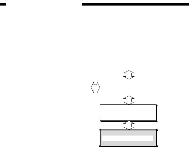
Installation of the printer board enables a copier to function as a printer.
|
|
|
|
|
|
|
|
|
|
|
|
Page |
Image |
|
|
|
memory |
processor |
|
|
|
PCB |
PCB |
|
|
|
|
|
|
|
|
|
|
|
|
Image server (hard disk) |
|
|
MFC PCB |
|
|
|
|
|
||
|
|
|
|
|
|
System motherboard
Network Printer Board-F1
Figure 1-201
1-2 |
COPYRIGHT © 1999 CANON INC. CANON Network Printer Board-F1 REV.0 FEB. 1999 PRINTED IN JAPAN (IMPRIME AU JAPON) |
CHAPTER 1 GENERAL DESCRIPTION
III . FEATURES
1.The printer board is equipped with a RISC-type MIPS R5000 CPU (operating frequency of 200 MHz) for high processing capabilities and a 32-MB memory (DIMM), enabling highspeed processing of print data.
2.The printer board possesses a PostScript 3 interpreter, and comes standard with 136 alphanumeric fonts.
3.The printer board supports not only 10Base-T (Ethernet) but also 100Base-TX (high-speed Ethernet). With its AUI connector, it may be connected directly to a 10Base5 port (for 10Base2, it may be connected by way of an external transceiver).
4.The printer board comes standard with a hard disk drive (2.1 GB) for spooling print jobs and downloading external fonts.
5.On a TCP/IP network, print jobs may be controlled using a browser (Netscape Navigator, Internet Explorer).
6.The printer board supports "SMB over TCP/IP," in which an SMB (Server Message Block, a common protocol for Windows files/printer) is used in a TCP/IP environment, enabling its host copier to function as a network printer in a network operating solely on Windows 95/98.
COPYRIGHT © 1999 CANON INC. CANON Network Printer Board-F1 REV.0 FEB. 1999 PRINTED IN JAPAN (IMPRIME AU JAPON) |
1-3 |

CHAPTER 1 GENERAL DESCRIPTION
IV . SPECIFICATIONS
Item |
Description |
||
|
|
|
|
CPU |
|
MIPS, R5000, 200MHz |
|
|
|
|
|
RAM |
Configuration |
168-pin DIMM, 2 slots |
|
|
|
|
|
|
Type |
SDRAM |
|
|
|
|
|
|
Access time |
10 nsec |
|
|
|
|
|
|
Memory size |
32-MB DIMM × 1 (standard) |
|
|
|
32-MB DIMM × 1 (option) |
|
|
|
|
|
Hard disk drive |
Memory size |
2.1 GB |
|
|
|
|
|
|
Interface |
E-IDE |
|
|
|
|
|
Parallel interface |
Standards |
IEEE1284 (bi-Centronics) |
|
|
|
|
|
|
Connector |
IEEE 1284B receptacle (36-pin connector) |
|
|
|
|
|
Network |
Standards |
Ethernet |
|
interface |
|
|
|
Connector |
RJ-45 (10Base-T/100Base-TX) |
||
|
|||
|
|
AUI (10Base5) |
|
|
|
|
|
Operating system |
|
Windows NT 4.0 |
|
|
|
Windows 95/98 |
|
|
|
Mac OS 7.6.1 or later |
|
|
|
|
|
Protocol |
|
TCP/IP (LPD, SMB over TCP/IP) |
|
|
|
IPX/SPX (PServer, NDS) |
|
|
|
AppleTalk (PAP) |
|
|
|
||
Page description language |
PostScript 3, PS |
||
|
|
|
|
Font |
|
136 alphanumeric fonts |
|
|
|
Multiple Master Font (2 types) |
|
|
|
|
|
Print paper size |
|
A3, A4, A5, B4, B5 |
|
|
|
STMT, LTR, LGL, 279.4 × 431.8 mm (11" × 17"), Executive |
|
|
|
|
|
Non-image width |
|
5 ±0.5 mm (on all sides) |
|
|
|
|
|
1-4 |
COPYRIGHT © 1999 CANON INC. CANON Network Printer Board-F1 REV.0 FEB. 1999 PRINTED IN JAPAN (IMPRIME AU JAPON) |

CHAPTER 1 GENERAL DESCRIPTION
V . EXTERNAL VIEW
Figure 1-501 is an external view of the printer board.
 Connector for Parallel port (Centronics)
 RJ-45 connector for 10/100BaseT twisted pair Ethernet

 AUI connector for 10Base2 or 10Base5
 Handle
 Air vent
Figure 1-501
COPYRIGHT © 1999 CANON INC. CANON Network Printer Board-F1 REV.0 FEB. 1999 PRINTED IN JAPAN (IMPRIME AU JAPON) |
1-5 |

CHAPTER 1 GENERAL DESCRIPTION
VI . OPERATION
A.Outline
To bring up the Printer screen on the copier's touch panel display, press the OPTIONS key on the copier's control panel.
The printer board may be used in normal mode (for normal printing jobs) or in settings mode (for making various settings). When the printer board starts up, press the Run Setup key (shown on the copier's touch panel display) to start settings mode. The printer board will automatically start in normal mode if the key is not pressed. (The Run Setup key is shown only for a few seconds after the power has been turned on so that the user will not start settings mode inadvertently.)
B.Settings Mode
The settings items consist of the following, each divided into sub items:
1.Server Setup
2.Network Setup
3.Printer Setup
4.PS Setup
5.Copier Setup
6.Job Log Setup
7.Change Password
8.Clear Serve
For detailed information on settings, see the Administrator Guide.
C.Normal Mode
Normal mode offers the following four screens:
1.Info screen
2.RIP screen
3.Print screen
4.Functions screen
At time of start-up, the Info screen appears. (The screen remains while no print job is being processed.) When a print job arrives and processing starts, the RIP screen appears. The Print screen appears at the end of processing (i.e., when transfer of image data to the host copier starts), and the Info screen appears once again when printing ends.
Figure 1-601 shows the Info screen.
1-6 |
COPYRIGHT © 1999 CANON INC. CANON Network Printer Board-F1 REV.0 FEB. 1999 PRINTED IN JAPAN (IMPRIME AU JAPON) |

|
CHAPTER 1 GENERAL DESCRIPTION |
Printer name |
|
(configured in Setup) |
PS: |
|
|
Printer status |
PostScript |
option is |
|
|
installed. |
Available space on the HDD |
|
|
|
|
MONITOR |
System software version
Figure 1-601
D.Test Print
The printer board is equipped with a function capable of generating the following test prints used to check operations and various settings:
• Test Page
Shows some of the settings of the printer board. It may be used to check the connection between the printer board and the host copier.
• Configuration
Shows settings of the printer board.
• Job Log
Provides a log of the most recent 55 jobs (file names, user names, and other control information).
• Font List
Provides a list of fonts stored on the built-in hard disk of the printer board. A test print may be generated by performing the following:
1)Press the OPTIONs key on the copier's control panel so that the Printer screen appears on the touch panel display.
2)Select 'Functions'.
3)Select 'Print Pages'.
4)Select 'Test Page'.
COPYRIGHT © 1999 CANON INC. CANON Network Printer Board-F1 REV.0 FEB. 1999 PRINTED IN JAPAN (IMPRIME AU JAPON) |
1-7 |

CHAPTER 2
BASIC OPERATIONS
I. |
CONSTRUCTION ....................... |
2-1 |
|
|
A. |
Printer Board Unit .................. |
2-1 |
|
B. Parts of the Printer Board by |
|
|
|
|
Function ................................. |
2-2 |
II. |
BASIC OPERATIONS ................. |
2-4 |
|
|
A. |
Start-Up Sequence ................ |
2-4 |
|
B. |
Printing ................................... |
2-6 |
III. TRANSFERRING PRINT DATA |
2-8 |
||
|
.................................................... |
|
|
|
A. Connecting to the Parallel Port |
||
|
|
............................................... |
2-8 |
|
B. Connecting to a Network ....... |
2-9 |
|
IV . PROCESSING PRINT DATA ... |
2-15 |
||
A. |
Making a Connection ........... |
2-15 |
B. Print Data Processing Block |
2-17 |
|
|
............................................. |
|
C. Image Data Output Block .... |
2-18 |
|
V . PROCESSING ON THE COPIER |
||
.................................................. |
|
2-19 |
A. |
Printing Image Data ............. |
2-19 |
VI . FAN .......................................... |
2-21 |
|
A. |
Outline .................................. |
2-21 |
VII . POWER SUPPLY .................... |
2-22 |
|
A. |
Outline .................................. |
2-22 |
B. |
Backup Battery .................... |
2-23 |
COPYRIGHT © 1999 CANON INC. CANON Network Printer Board-F1 REV.0 FEB. 1999 PRINTED IN JAPAN (IMPRIME AU JAPON)

CHAPTER 2 BASIC OPERATIONS
I . CONSTRUCTION
A.Printer Board Unit
The printer board contains the printer board and the hard disk drive (HDD).
The CPU, RAM (DIMM), flash ROM, and interface circuit are all mounted on the printer board.
The hard disk contains system software and user software distributed through a network by means of WebTools. It also stores print data (in a queue), records print jobs, and contains fonts installed additionally.
Printer board
Fan
HDD
Figure 2-101
COPYRIGHT © 1999 CANON INC. CANON Network Printer Board-F1 REV.0 FEB. 1999 PRINTED IN JAPAN (IMPRIME AU JAPON) |
2-1 |
CHAPTER 2 BASIC OPERATIONS
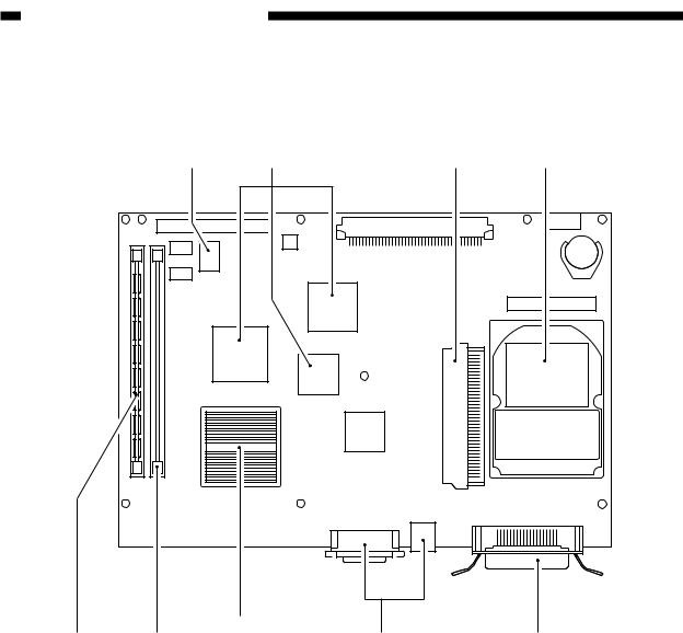
B.Parts of the Printer Board by Function
The printer board has the following parts, each with its own function:
Flash ROM RIP chips |
PCI slot |
Hard disk |
|
CPU |
|
|
DIMM |
DIMM |
Network interface |
Parallel interface |
|
Expansion slots |
|
|
Figure 2-102 (top view)
CPU
It is a RISC type CPU (MIPS R5000) capable of high processing speed. It processes data according to the instructions of the programs in memory.
DIMM
The DIMM area is roughly divided into a system area and an image data area: in the system area are found the program used to control the overall operation of the printer board and the program called a "PostScript interpreter," which interprets PostScript commands to generate image data; the image data area is used to store image data generated from PostScript files.
Flash ROM
The flash ROM contains the programs for running self diagnosis (driven at start-up), for booting the system program, for formatting the hard disk and writing the system program.
RIP Chip
The RIP chip is used to transfer data between memories and control the interface, thereby ensuring that the CPU processes print data efficiently.
2-2 |
COPYRIGHT © 1999 CANON INC. CANON Network Printer Board-F1 REV.0 FEB. 1999 PRINTED IN JAPAN (IMPRIME AU JAPON) |
CHAPTER 2 BASIC OPERATIONS
Network Interface
It is used for connection to a network, and supports 10Base and 100Base-TX Ethernet systems.
Parallel Interface
It is used for connection to a computer, and is compatible with IEEE1284 standards.
PCI Slot
It is a 32-bit PCI (Peripheral Component Interconnect) connector for future expansion.
COPYRIGHT © 1999 CANON INC. CANON Network Printer Board-F1 REV.0 FEB. 1999 PRINTED IN JAPAN (IMPRIME AU JAPON) |
2-3 |

CHAPTER 2 BASIC OPERATIONS
II . BASIC OPERATIONS
A.Start-Up Sequence
When the copier's main power switch is turned on, the system power supply is provided with power, ultimately supplying the EX board and the printer board unit with power.
When the printer board is supplied with power, its CPU runs the self diagnosis program stored in its flash ROM, showing the result on the copier's control panel.
When a check on each part ends normally, the boot program stored also in the flash ROM starts to read the system program from the hard disk drive for writing to the main memory.
When the write operation ends, the system program starts and shows the Idle message on the touch display as soon as all parts have been properly prepared.
The system program of the printer board consists of a number of modules, of which the ones needed for the processing in question are called into the system area of the main memory (RAM).
'Idle' is indicated in response to the end of start-up operations.
Copier |
|
|
|
|
|
|
Copying |
Copying |
|
|
|
|
|
Error |
Error Data MAIL Error |
Data |
Error |
ON/OFF |
||
COPY A |
COPY B |
BOX |
|
OPTIONS |
|
|
|
1 |
2 |
3 |
|
|
Control |
|
9 |
5 |
6 |
|
|
|
|
4 |
|
|
|||
|
7C |
8 |
9 |
|
|
|
|
|
|
panel |
|||
|
ID |
0 |
C |
|
|
|
|
|
|
|
|
|
|
Image |
MFC PCB |
|
System |
|||
processor |
|
mother- |
||||
PCB |
|
|
|
|
|
board |
Printer board |
|
|
|
|
RAM (DIMM) |
|
|
|
System |
Image |
|
|
area |
data area |
|
DP |
CPU |
|
Interface |
|
|
||
RAM |
|
|
|
|
Self diagnosis |
Boot |
System |
|
program |
||
|
program |
program |
|
|
Flash ROM |
Hard disk drive |
|
|
|
||
:Access to the program in operation.
:Flow of the system program.
Figure 2-201
2-4 |
COPYRIGHT © 1999 CANON INC. CANON Network Printer Board-F1 REV.0 FEB. 1999 PRINTED IN JAPAN (IMPRIME AU JAPON) |

CHAPTER 2 BASIC OPERATIONS
The CPU on the copier's IP board and the CPU of the printer board writes test data to the DPRAM mounted on the printer board (for CPU communication) to check the printer board. If a fault is detected, the copier's touch display will indicate an error code (E677).
'E677' is indicated in response to a fault in CPU communication.
Copier |
|
|
|
|
|
Copying |
Copying |
|
|
|
|
Error |
Error Data MAIL Error |
Data |
Error |
||
COPY A |
COPY B |
BOX |
|
OPTIONS |
ON/OFF |
|
1 |
2 |
3 |
|
Control |
|
4 |
5 |
6 |
|
|
|
7 |
8 |
9 |
|
|
|
|
panel |
|||
|
ID |
0 |
C |
|
|
|
|
|
|
|
|
CPU |
|
|
|
|
|
Image |
MFC PCB |
System |
|||
processor |
mother- |
||||
PCB |
|
|
|
|
board |
Printer board |
|
|
|
|
RAM (DIMM) |
|
|
|
System |
Image |
|
|
area |
data area |
|
DP |
CPU |
Interface |
|
|
|||
RAM |
|
|
|
|
Self diagnosis |
Boot |
|
|
program |
program |
Hard disk drive |
|
Flash ROM |
||
|
|
||
:Access to the program in operation.
:DPRAM write test.
Figure 2-202
COPYRIGHT © 1999 CANON INC. CANON Network Printer Board-F1 REV.0 FEB. 1999 PRINTED IN JAPAN (IMPRIME AU JAPON) |
2-5 |

CHAPTER 2 BASIC OPERATIONS
B.Printing
1.Processing on the Computer Side
In response to a print command from the user, the application program sends image data to the printer drive with the help of the operating system.
The printer driver then translates the image data and the printer settings information into PostScript commands. The print data described in the page description language (i.e., PostScript) is sent to the printer board through the parallel port or the network port depending on the type of connection used between the printer board and the computer.
The printer driver for the printer board is stored on the CD-ROM that comes with the board.
Application |
|
Operating system |
|
|
|
|
|
||
program |
Printer driver |
|
||
|
|
|||
Image data |
PostScript |
|
Parallel port |
|
data |
Print job |
|||
driver |
||||
|
generation |
|
||
|
|
|
||
|
Settings |
|
|
|
|
information |
|
Network |
|
|
Printer |
|
driver |
|
|
|
|
||
|
property |
|
|
|
Image data.
Print job
(print data in PostScript).
 Settings information.
To the parallel port
To the network
Figure 2-203
2-6 |
COPYRIGHT © 1999 CANON INC. CANON Network Printer Board-F1 REV.0 FEB. 1999 PRINTED IN JAPAN (IMPRIME AU JAPON) |
CHAPTER 2 BASIC OPERATIONS
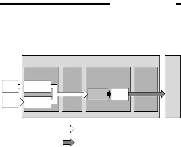
2.Processing on the Printer Board Side
The print data input block of the printer board serves to send print data from the computer to the print data processing block using the selected type of connection. In response, the print data processing block generates image data from PostScript print data so that the copier can print it.
When data is ready for transmission to the copier, the image data output block sends it to the copier on a page-by-page basis.
|
|
Printer board |
|
Copier |
|
|
Print data input |
Data |
Print data processing |
Image data |
|
|
block |
connection |
block |
|
output block |
Print job |
Parallel |
|
|
|
|
interface |
|
|
|
|
|
|
|
PostScript |
Image |
|
|
|
|
|
|
||
|
Network |
|
data |
data |
|
Print job |
|
|
|
|
|
interface |
|
|
|
|
|
|
|
|
|
|
|
Print job
(print data in PostScript).
Image data.
Figure 2-204
The copier exposes its photosensitive drum according to the data it has received and turns out print images by means of development, transfer, and fixing.
COPYRIGHT © 1999 CANON INC. CANON Network Printer Board-F1 REV.0 FEB. 1999 PRINTED IN JAPAN (IMPRIME AU JAPON) |
2-7 |
CHAPTER 2 BASIC OPERATIONS
III . TRANSFERRING PRINT DATA
The printer board provides a parallel interface on a network interface for connection to a computer. Both these interfaces may be used concurrently.
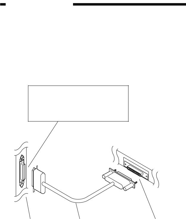
A.Connecting to the Parallel Port
The parallel port is designed to comply with IEEE1284 (commonly known as "bi-Centronics" standards). It supports an existing Centronics interface, a nibble interface (in which data is sent to the computer in 4-bit units), and an ECP (Enhanced Capability Port) interface (in which data is exchanged in both directions in 8-bit units at a high speed).
Reference:
Selecting the Parallel Port Connection
Run Setup>Network Setup>Port Setup>Parallel Port Setup Enable Parallel Port: Yes*
Port Timeout in Seconds Ignore EOF Character *Must be set as indicated.
Printer board
Computer
Parallel port |
Centronics cable |
Parallel port (printer port) |
|
(IEEE1284-compatible cable) |
|
Figure 2-301
2-8 |
COPYRIGHT © 1999 CANON INC. CANON Network Printer Board-F1 REV.0 FEB. 1999 PRINTED IN JAPAN (IMPRIME AU JAPON) |
CHAPTER 2 BASIC OPERATIONS
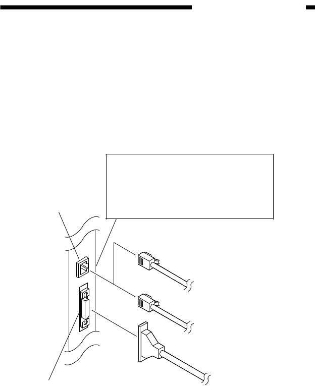
B.Connecting to a Network
1.Outline
The printer board comes standard with an interface for an Ethernet network; i.e., it provides an AUI connector for 10Base5, and an RJ-45 connector for 10/100Base-T.
In the case of 10Base5, connect an AUI cable to the AUI connector. The AUI connector and the RJ-45 connector are connected as a network port and, therefore, cannot be used concurrently. (Do not connect cables to both connectors at any time.)
The 100Base standards supported by the printer board are 100Base-TX. The printer board is equipped with a function that automatically switches between 10Base-T and 100Base-TX, capable of operation on a network on which both speeds are used. (Select 'Auto Detect' under 'Ethernet Speed'.) If auto detection fails to operate on a HUB equipped with a 10Base/100Base auto switch, advise the network supervisor to select a fixed speed.
RJ-45 connector
Printer board
Reference
Selecting Network Connection
Run Setup>Network Setup>Port Setup>Ethernet Setup Enable Ethernet: Yes*
*Must be set as indicated. Ethernet Speed
After selecting the port, you need to select the appropriate protocol and service settings.
100Base-TX Category 5STP cable
10Base-T
Category 3STP cable or Category 5STP cable
|
10Base 5 |
AUI connector |
AUI transceiver |
|
Figure 2-302
COPYRIGHT © 1999 CANON INC. CANON Network Printer Board-F1 REV.0 FEB. 1999 PRINTED IN JAPAN (IMPRIME AU JAPON) |
2-9 |
Loading...