


F1
Table of contents
 Loading...
Duplex Color Image Reader - F1
Product Outline
Technology
Periodic Servicing
Parts Replacing and Cleaning
Adjustments
Installation
Appendix
Service Manual
April 11, 2013
Revision 0
654321

Application
This manual has been issued by Canon Inc. for qualied persons to learn technical theory,
installation, maintenance, and repair of products. This manual covers all localities where the
products are sold. For this reason, there may be information in this manual that does not
apply to your locality.
Corrections
This manual may contain technical inaccuracies or typographical errors due to improvements
or changes in products. When changes occur in applicable products or in the contents of this
manual, Canon will release technical information as the need arises. In the event of major
changes in the contents of this manual over a long or short period, Canon will issue a new
edition of this manual.
The following paragraph does not apply to any countries where such provisions are
inconsistent with local law.
Trademarks
The product names and company names used in this manual are the registered trademarks
of the individual companies.
Copyright
This manual is copyrighted with all rights reserved. Under the copyright laws, this manual may
not be copied, reproduced or translated into another language, in whole or in part, without the
written consent of Canon Inc.
(C) CANON INC. 2012
Caution
Use of this manual should be strictly supervised to avoid disclosure of condential
information.
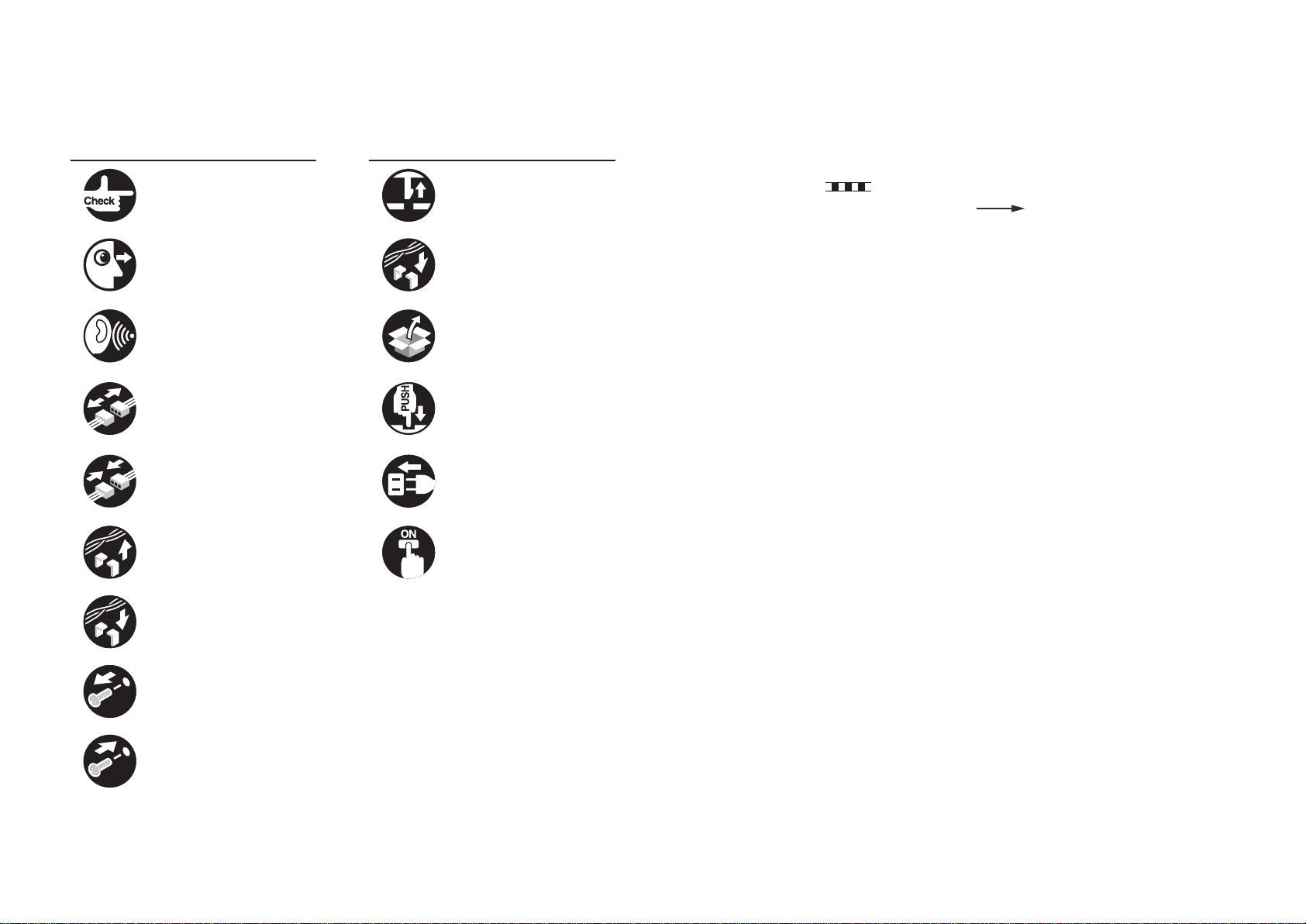
Explanation of Symbols
The following symbols are used throughout this Service Manual.
Symbols Explanation Symbols Explanation
Check. Remove the claw.
Check visually. Insert the claw.
The following rules apply throughout this Service Manual:
1. Each chapter contains sections explaining the purpose of specic functions and the
relationship between electrical and mechanical systems with reference to the timing of
operation.
In the diagrams, represents the path of mechanical drive; where a signal
name accompanies the symbol, the arrow
indicates the direction of the
electric signal.
The expression "turn on the power" means ipping on the power switch, closing the
front door, and closing the delivery unit door, which results in supplying the machine with
power.
Check the noise. Use the bundled part.
Disconnect the connector. Push the part.
Connect the connector. Plug the power cable.
Remove the cable/wire
from the cable guide or wire
saddle.
Set the cable/wire to the
cable guide or wire saddle.
Remove the screw.
Tighten the screw.
Turn on the power.
2. In the digital circuits, '1' is used to indicate that the voltage level of a given signal is
"High", while '0' is used to indicate "Low". (The voltage value, however, differs from
circuit to circuit.) In addition, the asterisk (*) as in "DRMD*" indicates that the DRMD
signal goes on when '0'.
In practically all cases, the internal mechanisms of a microprocessor cannot be checked
in the eld. Therefore, the operations of the microprocessors used in the machines
are not discussed: they are explained in terms of from sensors to the input of the DC
controller PCB and from the output of the DC controller PCB to the loads.
The descriptions in this Service Manual are subject to change without notice for product
improvement or other purposes, and major changes will be communicated in the form of
Service Information bulletins.
All service persons are expected to have a good understanding of the contents of this Service
Manual and all relevant Service Information bulletins and be able to identify and isolate faults
in the machine.

Contents
1
Product Outline
Characteristic ------------------------------------------------------------------1-2
High Speed 2-Side Scan-at One Time (DADF) ---------------------------- 1-2
High Capacity Pickup Tray (DADF) ------------------------------------------- 1-2
Next Generation Scanner Unit (DADF/Reader) ---------------------------- 1-2
Specication --------------------------------------------------------------------1-3
Reader -------------------------------------------------------------------------------- 1-3
DADF --------------------------------------------------------------------------------- 1-4
Names of Parts ----------------------------------------------------------------1-5
External View ----------------------------------------------------------------------- 1-5
Cross-section View ---------------------------------------------------------------- 1-6
Basic Operation ---------------------------------------------------------------1-6
Original Set Display --------------------------------------------------------------- 1-6
Option conguration ----------------------------------------------------------1-7
2
Technology
Basic conguration -----------------------------------------------------------2-2
Reader -------------------------------------------------------------------------------- 2-2
DADF --------------------------------------------------------------------------------- 2-7
Controls ------------------------------------------------------------------------ 2-18
Reader -------------------------------------------------------------------------------2-18
DADF --------------------------------------------------------------------------------2-32
Service Work ----------------------------------------------------------------- 2-57
Reader -------------------------------------------------------------------------------2-57
DADF --------------------------------------------------------------------------------2-58
3
Periodic Servicing
Periodic Servicing List -------------------------------------------------------3-2
Reader -------------------------------------------------------------------------------- 3-2
DADF --------------------------------------------------------------------------------- 3-4
4
Parts Replacing and Cleaning
Parts List (Reader) ------------------------------------------------------------4-2
External Covers (Reader) -------------------------------------------------------- 4-2
Main unit (Reader) ----------------------------------------------------------------- 4-2
List of Periodical Consumable Parts/Locations
for Periodical Cleaning (Reader) ----------------------------------------------- 4-3
Motor (Reader) --------------------------------------------------------------------- 4-3
Fan (Reader) ------------------------------------------------------------------------ 4-4
Sensor (Reader) ------------------------------------------------------------------- 4-4
PCB (Reader) ----------------------------------------------------------------------- 4-5
Connector Layout Drawing (Reader) ----------------------------------------- 4-6
Removing from the connection equipment (Reader)-----------------4-7
Removing the DADF + Reader Unit ------------------------------------------- 4-7
Major Unit (Reader) -------------------------------------------------------- 4-14
Removing the Scanner Unit (Reader) ---------------------------------------4-14
Removing the Reader Controller PCB ---------------------------------------4-16
External Auxiliary System (Reader) ------------------------------------ 4-18
Removing the Box Right Cover -----------------------------------------------4-18
Removing the Box Left Cover -------------------------------------------------4-18
Removing the Box Upper Cover ----------------------------------------------4-19
Removing the Upper Right Cover 1/Upper Left Cover ------------------4-19
Periodical Consumable Parts/Locations
for Periodical Cleaning (Reader)
Cleaning the Copyboard Glass (Large) -------------------------------------4-20
Cleaning the Copyboard Glass (Small) -------------------------------------4-21
Cleaning/Lubrication of the Scanner Rail -----------------------------------4-23
Parts List (DADF) ----------------------------------------------------------- 4-25
External Covers (DADF) --------------------------------------------------------4-25
Main Unit (DADF) -----------------------------------------------------------------4-25
List of Periodical Consumable Parts/Locations
for Periodical Cleaning (DADF) -----------------------------------------------4-26
---------------------------------------- 4-20

Solenoid (DADF) ------------------------------------------------------------------4-27
Motor (DADF) ----------------------------------------------------------------------4-27
Fan (DADF) ------------------------------------------------------------------------4-28
Lamps, Heaters, and Others (DADF) ----------------------------------------4-28
Sensor (DADF) --------------------------------------------------------------------4-29
PCB (DADF) -----------------------------------------------------------------------4-30
Connector Layout Drawing (DADF) ------------------------------------------ 4-31
Removing from the Connection Equipment (DADF) ---------------4-34
Removing the DADF -------------------------------------------------------------4-34
Major Units (DADF) --------------------------------------------------------- 4-36
Removing the DADF Scanner Unit -------------------------------------------4-36
Removing the Pickup Roller Unit ---------------------------------------------4-38
External Auxiliary System (DADF) -------------------------------------- 4-39
Removing the DADF Front Cover --------------------------------------------4-39
Removing the DADF Rear Cover ---------------------------------------------4-39
Installing the DADF White Sheet ----------------------------------------------4-40
Removing the Stamp Solenoid ------------------------------------------------ 4-41
Consumable parts for periodical replacement
and locations for cleaning (DADF)
Removing the Pickup Roller / Feed Roller ----------------------------------4-42
Removing the Separation Roller ---------------------------------------------- 4-44
Removing the Dust Collecting Sheets Type E -----------------------------4-45
Removing the Dust Collecting Sheets ---------------------------------------4-46
Removing the Stamp Cartridge -----------------------------------------------4-48
Cleaning the Back Surface of the Reading Glass ------------------------4-49
Cleaning the Post-separation Sensor 1/Post-separation Sensor 2
/Post-separation Sensor 3 ------------------------------------------------------4-50
Cleaning the Pullout Roller/Feed Roller 2/Lead Roller 1 --------------- 4-51
Cleaning the Registration Sensor/Lead Sensor/Registration Roller -4-53
Cleaning the Lead Roller 2/Lead Roller 3 ----------------------------------4-55
Cleaning the Delivery Roller/Delivery Sensor -----------------------------4-56
Height Adjustment ----------------------------------------------------------------4-57
5
Adjustments
-------------------------------------- 4-42
Overview ------------------------------------------------------------------------5-2
Reader -------------------------------------------------------------------------------- 5-2
DADF
--------------------------------------------------------------------------------- 5-3
Service mode backup ------------------------------------------------------------- 5-4
Adjustment Method -----------------------------------------------------------5-5
Measurement during Reader Controller PCB Replacement
and After RAM Clear -------------------------------------------------------------- 5-5
Processing after Scanner Unit Replacement ------------------------------- 5-7
Processing after Copyboard Glass Replacement ------------------------- 5-9
Preparation or Creation of Test Chart ----------------------------------------5-10
Angle Restriction Release (Opening Angle at 90 deg) ------------------ 5-10
Sensor Output Adjustment ------------------------------------------------------ 5-11
Tray Width Adjustment----------------------------------------------------------- 5-11
Tilt Adjustment ---------------------------------------------------------------------5-12
Height Adjustment ----------------------------------------------------------------5-12
Right Angle Adjustment ----------------------------------------------------------5-15
Registration Roller Wheel Skew Adjustment ------------------------------- 5-16
Stream Reading Adjustment --------------------------------------------------- 5-18
Side Registration Adjustment --------------------------------------------------5-19
Leading Edge Registration Adjustment--------------------------------------5-20
Magnication Adjustment -------------------------------------------------------5-21
White Level Adjustment ---------------------------------------------------------5-22
Hinge Pressure Adjustment ---------------------------------------------------- 5-22
6
Installation
How to check this installation procedure --------------------------------6-2
When using the parts included in the package ----------------------------- 6-2
Symbols in the illustration -------------------------------------------------------- 6-2
Product Name ------------------------------------------------------------------6-2
Point to Note About Installation
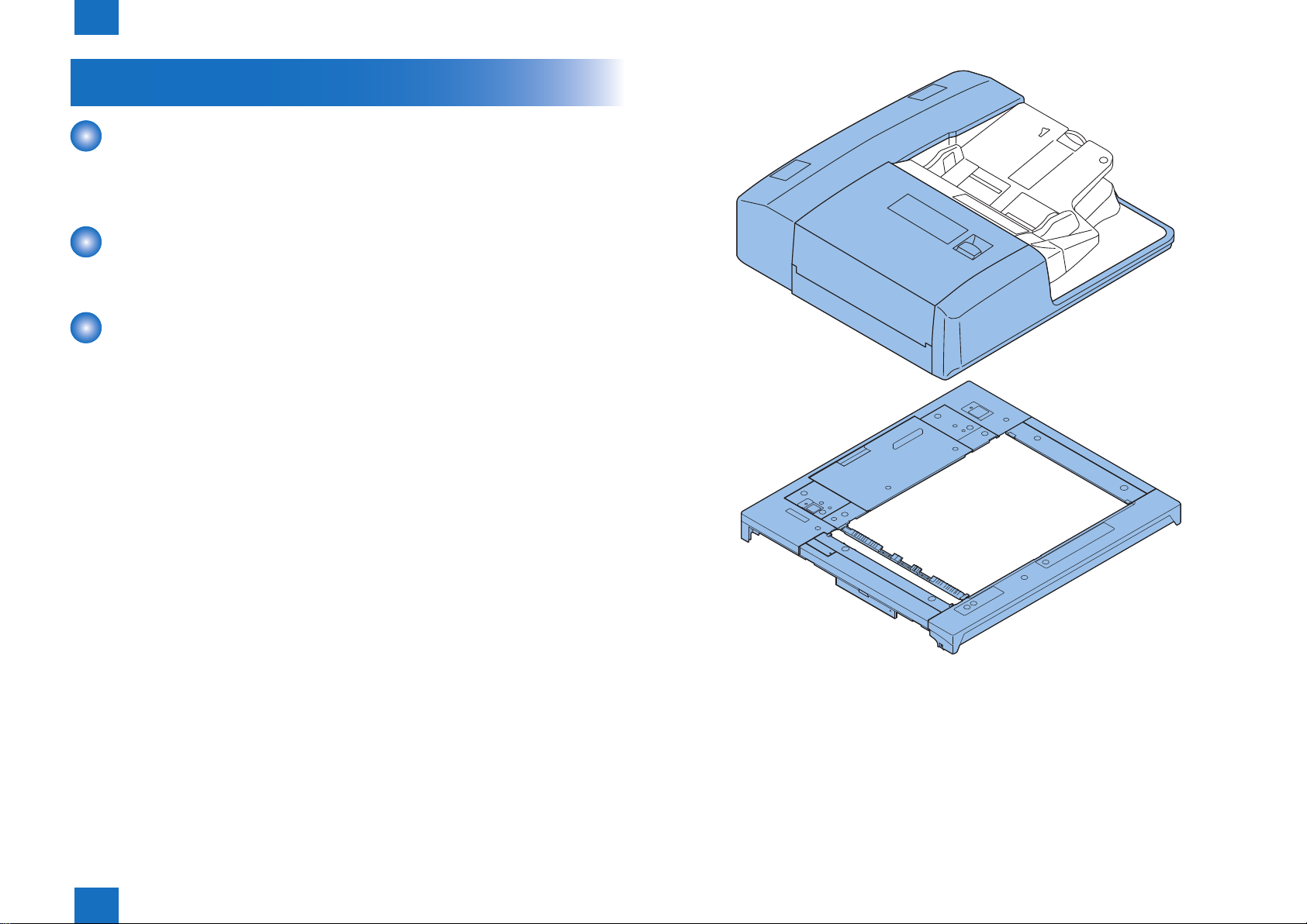
Checking the Contents
Contents of the Equipment ------------------------------------------------------ 6-3
Contents of the Host Machine -------------------------------------------------- 6-3
------------------------------------------------------6-3
--------------------------------------------6-2
Turning OFF the power of the host machine ---------------------------6-4
Installation Outline Drawing
Unpacking of the Reader Unit
Installation Procedure
Connecting this Machine --------------------------------------------------------- 6-6
------------------------------------------------6-4
---------------------------------------------6-4
--------------------------------------------------------6-6

Installing the Stamp Ink Cartridge --------------------------------------------6-15
Afxing Labels ---------------------------------------------------------------------6-17
Operation Check ------------------------------------------------------------ 6-17
Performing Auto Adjust Gradation
--------------------------------------6-18
Appendix
Service Tools --------------------------------------------------------------------- II
Special Tools --------------------------------------------------------------------------- II
List of Oils/Solvents ------------------------------------------------------------------ II
General Circuit Diagram -------------------------------------------------------III
Reader ---------------------------------------------------------------------------------- III
DADF (1/2) ---------------------------------------------------------------------------- IV
DADF (2/2) -----------------------------------------------------------------------------V

Product Outline
1
Characteristic
■
Specication
■
Names of Parts
■
Basic Operation
■
Option conguration
■
Product Outline
1
1
Product Outline > Characteristic > Next Generation Scanner Unit (DADF/Reader)
Characteristic
High Speed 2-Side Scan-at One Time (DADF)
• Maximum 200 ipm (2 side, B/W, 300 dpi).
• Color scan is also available, maximum 80 ipm (one side/2-side, 300 dpi).
High Capacity Pickup Tray (DADF)
• Maximum document loading is 300 sheets (80 g/m2 or lower).
Next Generation Scanner Unit (DADF/Reader)
• Adapting the reading sensor uniquely developed, allows low power consumption and high-
speed drive.
• Exposure to light by white color LED, enables low power consumption, size reducing, and
color balance improvement.
• Color aberration-free.
1-2
Product Outline > Characteristic > Next Generation Scanner Unit (DADF/Reader)
1
F-1-1
1-2

1
Product Outline > Specication > Reader
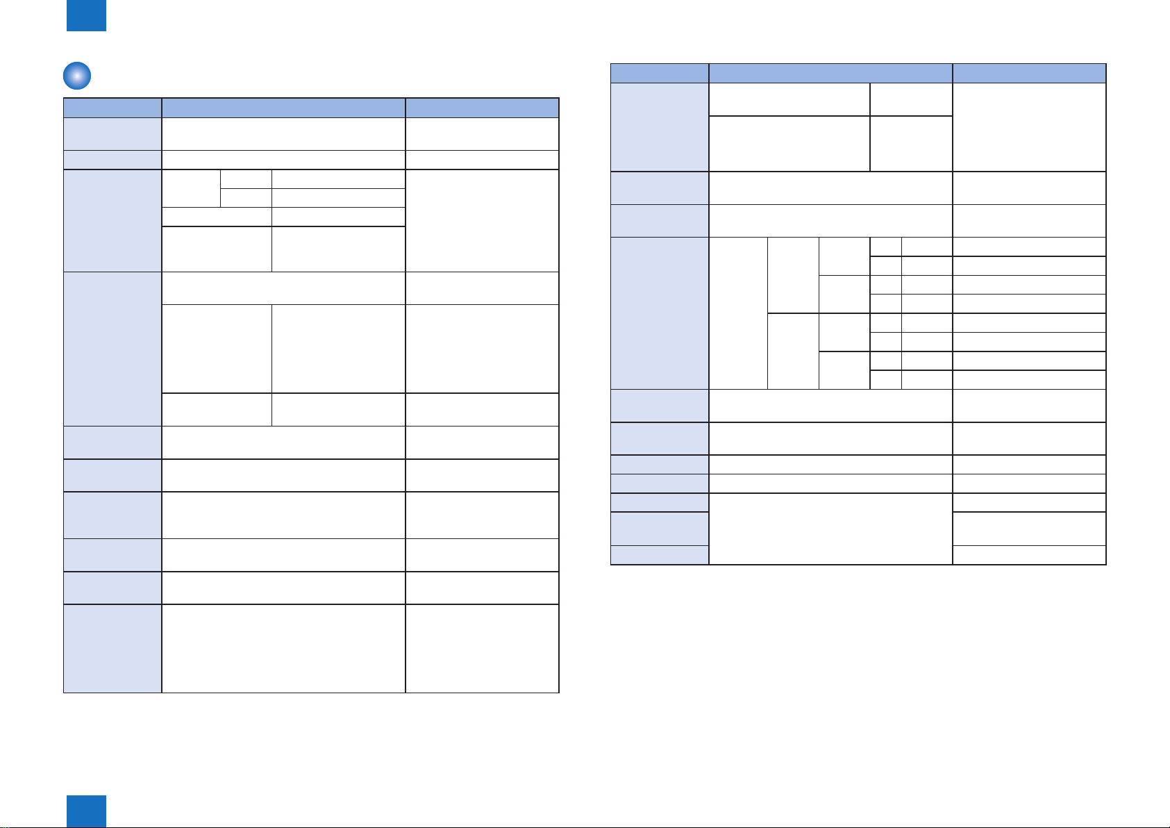
Specication
Following shows the specication list of this equipment.
Reader
Item Specication/function Remarks
Exposure system High-brightness white LED + reection
plate
Original
scan
Scanning resolution 600 dpi x 600 dpi SEND: 300 x 300 dpi
Gradation 256 gradations Carriage position detection Scanner unit HP sensor (SR2) Magnication change 25% to 400% Digital reproduction (Color:
Number of line of reading
sensor
Original
size
detection
Maximum
original
size
Power source DC 24.5V, DC 12.3V It is supplied by the
Dimension 635 x 590 x 72 (W x D x H mm) DADF is not counted for the
Weight Approx. 12 kg -
Option Reader heater -
Contents of description are subject to change due to product improvement etc.
In BOOK mode Scan by movement of scanner unit In DADF mode Scan by original stream reading with
scanner unit xed
In main scanning
direction
In sub scanning
direction
In BOOK mode Horizontal scanning direction: detection
In DADF mode Horizontal scanning direction:
In BOOK mode 297 mm x 431.8 mm In DADF mode 304.8 mm x 630 mm -
Image processing in main controller PCB -
Image processing in main controller PCB Some are processed by the
4 lines (R, G, B, B/W) -
by reading sensor (scanner unit)
Vertical scanning direction: detection by
reection sensor (original size sensor 1
(AB type) or original si ze sensor 2 (Inch
type)
detection by the original width volume/
photointerrupter on DADF
Vertical scanning direction: detection by
the photointerrupter on DADF
-
-
in case of 300 dpi or
less, scan reproduction
(double speed scan) is also
included).
reader controller PCB.
-
-
-
-
connected device.
height.
T-1-1
1-3
Product Outline > Specication > Reader
1
1-3
1
Product Outline > Specication > DADF
1-4
DADF
Item Specication Remarks
Original pickup
method
Type of original Sheet original -
Grammage of
original
Original size A3, A4, A4R, A5, A5R, B4, B5, B5R, B6R, LDR,
Setting direction
of original
Setting position of
original
Scanning method
of original
Separation
method of original
Feed mode of
original
Stacking capacity
of original tray
Auto pickup/delivery method Simultaneous 2-sided
scanning
1-sided A/B 38 to 220 g/m
Inch 50 to 220 g/m
2-sided 50 to 220 g/m
Color original 64 to 220 g/m
LGL, LTR, LTRR, STMT, STMTR
Feed direction 139.7 to 432 mm
(STMT to 17 inch)
* 432 to 630 mm
(refer to the remarks).
Width direction 128 to 304.8 mm
(B6R to 12 inch)
Original tray pickup: face-up stacking -
Original tray pickup: center reference -
Stream reading For simultaneous 2-sided
Retard separating method -
1-sided, 2-sided (simultaneous scanning) -
All sizes: 300 sheets
(in case of paper of 80 g/m
2
or lighter)
2
2
2
2
60 to 90 g/m2: If original
exceeds 432 mm, 1-sided,
1-sheet feeding.
64 to 220 g/m2 at B/W and
color mixed mode and if
original is B/W.
For B6, horizontal scanning
only
Since the original with 432 to
630 mm in feed direction is
larger than the original pickup
tray, user needs to hold it so
that the machine can scan
the original.
-
scanning, only the original of
432 mm or shorter.
- Grammage conversion for
original exceeding 80 g/m2.
- Folding original is subject to
height of 10 mm or shorter.
- 1 sheet stacking for original
exceeding 432 mm.
Item Specication Remarks
Mixed mode
function
Original size
detection function
Done stamp
function
Original
processing speed
Power source DC 24.5V, DC 5V It is supplied by the
Maximum power
consumption
Weight Approx. 27.4 kg -
Dimension 633 x 603 x 179 (W x D x H mm) -
Use condition Subject to connected device. -
Temperature
range
Humidity range -
Mix of same conguration
mode
Mix of different conguration
mode
Yes -
Yes -
Stream
scanning
180 W or less (including reader) Standby: 15 W or less
1-sided 600 dpi BW 120 ipm -
300 dpi BW 120 ipm -
2-sided 600 dpi BW 120 ipm -
300 dpi BW 200 ipm -
Yes - Original should be set at the
rear side.
Yes
CL 70 ipm -
CL 120 ipm -
CL 70 ipm -
CL 140 ipm -
- Assured combination for mix
with different conguration
AB type: A3/B4, B4/A4R, A4/
B5, B5R/A5R
connected device.
-
*1: Extra length mode is specied in Service Mode. Go through the following:
(Lv.2) COPIER > OPTION > USER > MF-LG-ST;
and select “1” (default: 0).
T-1-2
Product Outline > Specication > DADF
1
1-4
1
[4][8]
[3]
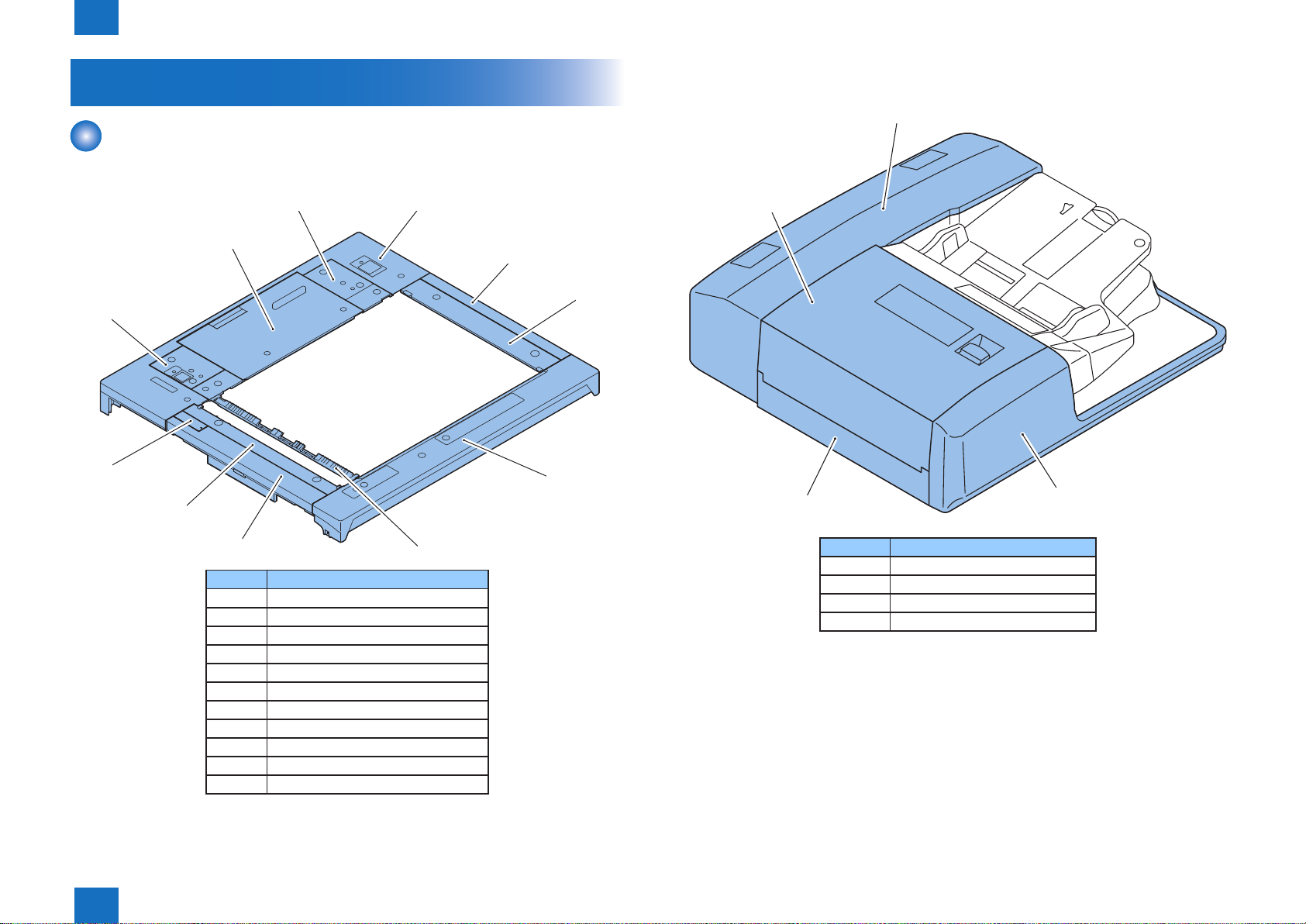
Product Outline > Names of Parts > External View > DADF
Names of Parts
External View
Reader
■
■
DADF
1-5
[4]
[9]
[11]
[5]
[7]
[2]
No.
[1] Front Cover
[2] Left Cover
[3] Right Cover
[4] Rear Cover
[5] PCB Cover
[6] Right Upper Panel
[7] Left Upper Panel
[8] DADF Base Right Cover
[9] DADF Base Left Cover
[10] Jump Base
[11] Left Upper Small Cover
[10]
[3]
[1]
[6]
F-1-2
[2]
No.
[1] Front Cover
[2] Left Cover
[3] Rear Cover
[4] Feeder Cover
[1]
F-1-3
T-1-3
Product Outline > Names of Parts > External View > DADF
1
1-5
1
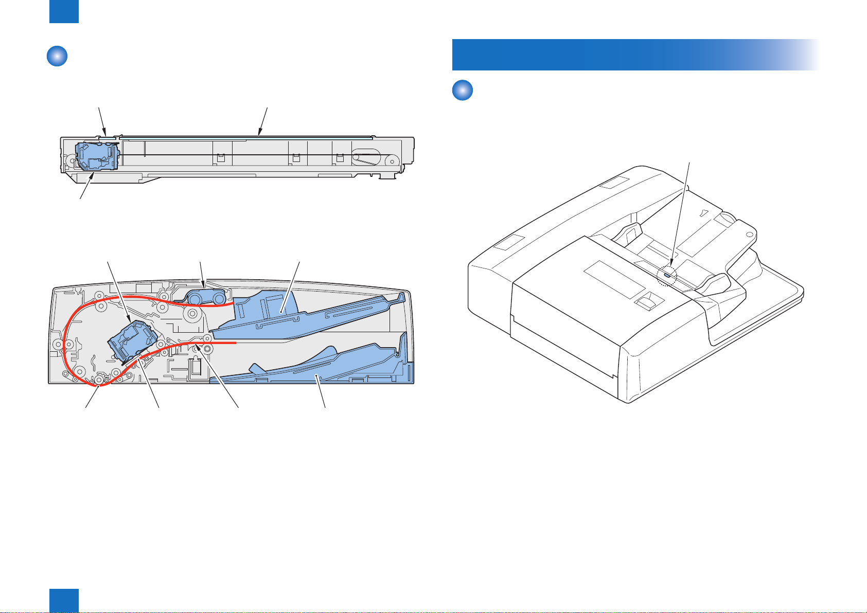
Stream reading glass Copyboard glass
Scanner unit Pickup roller unit Original pickup tray
Product Outline > Basic Operation > Original Set Display
1-6
Cross-section View
Reader
■
Scanner unit
DADF
■
Basic Operation
Original Set Display
The original set display LED is activated when the original is set on the original pickup tray.
When a jam is detected while the original is scanned, the original set display LED starts
ashing.
Original set display
F-1-4
Scanning position
(front side)
Product Outline > Basic Operation > Original Set Display
(rear side)
1
Original delivery trayPath of originalScanning position
F-1-5
F-1-6
1-6

1
Product Outline > Option conguration
Option conguration
Followings are the options for the host machine.
Reader heater
1-7
F-1-7
Product Outline > Option conguration
1
1-7

Technology
2
Basic conguration
■
Controls
■
Service Work
■
2
Technology
2
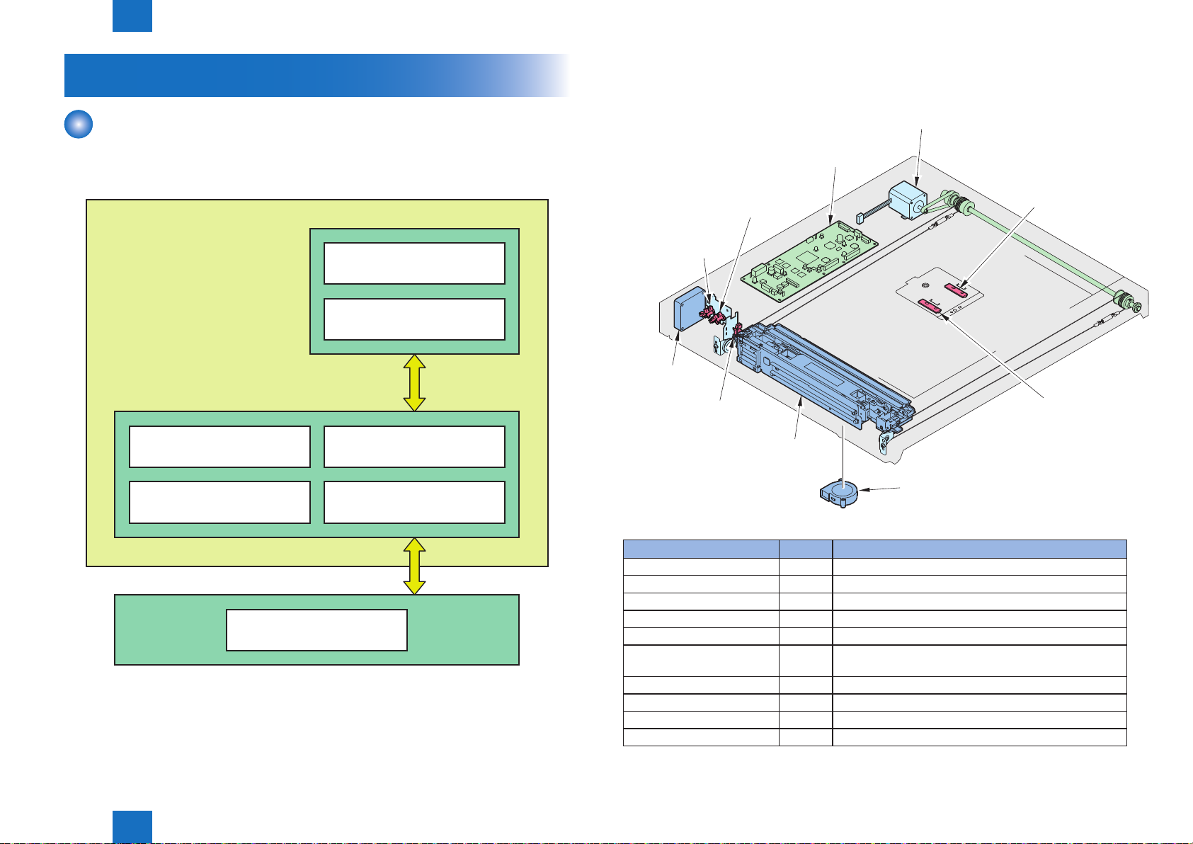
Scanner motor (M1)
Technology > Basic conguration > Reader > Parts conguration
Basic conguration
Reader
Parts conguration
■
Followings are the positions and names of main conguration parts.
2-2
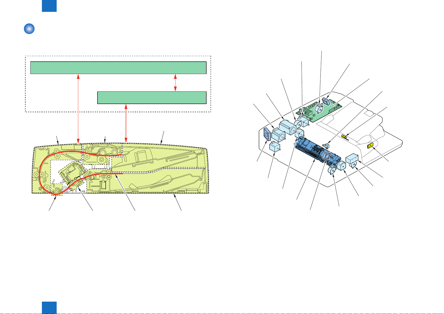
Function conguration
■
Following is the list of functions.
Reader controller PCB
Scanner drive
Main controller PCB
Scanner unitReader unit
Image scanning
A/D conversion
Original size detection
Image processingDust detection
Magnification change
F-2-1
Reader controller PCB
DADF
open/closed
DADF
open/closed
sensor 1
(SR1)
Scanner unit
exhaust fan (FM1)
home position sensor
Component part Symbol Function/specication
Scanner motor M1 2 phase pulse motor: pulse control
Scanner unit exhaust fan FM1 Exhaustion of scanner unit
Scanner unit cooling fan FM2 Cooling of scanner unit
DADF open/closed sensor 1 SR1 DADF open detection (DADF is detected at 5 degree)
Scanner unit HP sensor SR2 Scanner unit HP detection
DADF open/closed sensor 2 SR3 DADF open detection (size detection timing is detected
Original size sensor 1 CF1 Size detection in sub scanning direction (AB type)
Original size sensor 2 CF2 Size detection in sub scanning direction (INCH type)
Scanner unit --- Image reading, analog image processing
Reader controller PCB PCB1 Control of entire reader, digital image processing
sensor 2
(SR3)
Scanner unit
(SR2)
Scanner unit
(PCB1)
Original size sensor 2
(CF2)
Original size sensor 1
(CF1)
Scanner unit
cooling fan (FM2)
when DADF is open at 25 degree.
F-2-2
T-2-1
Technology > Basic conguration > Reader > Parts conguration
2
2-2
2
Technology > Basic conguration > Reader > Reader controller PCB
2-3
Overview of power circuit
■
Control of the host machine is conducted at the reader controller PCB.
Reader controller PCB also controls the DADF driver PCB and DADF scanner unit.
Following is the relations of each electrical part.
Motor
Fan
Host
machine
Error Code
E270 (Error in the main scanning/sub scanning synchronization signal).
-0001 Sub scanning synchronization signal (VSYNC) is not properly transmitted from scanner
unit PCB (front side scanner unit), and this causes image failure or abnormal termination.
-0002 Sub scanning synchronization signal (VSYNC) is not transmitted due to the error in the
main scanning synchronization signal (HSYNC), and this causes image failure or abnormal
termination.
-0101 Sub scanning synchronization signal (VSYNC) is not properly transmitted from scanner
unit PCB (back side scanner unit), and this causes image failure or abnormal termination.
E280 (Communication error between reader controller PCB – scanner unit)
- 0001 If the communication is not started within the specied time between reader controller
PCB – front side scanner unit.
- 0101 If the communication is not started within the specied time between reader controller
PCB – back side scanner unit.
E400 (Communication error between reader controller PCB – DADF)
-0001, -0002
If reception error occurs during communication between reader controller PCB - DADF
Reader
controller
PCB
Sensor
Scanner unit (reader)
Scanner unit (DADF)
DADF driver PCB
F-2-3
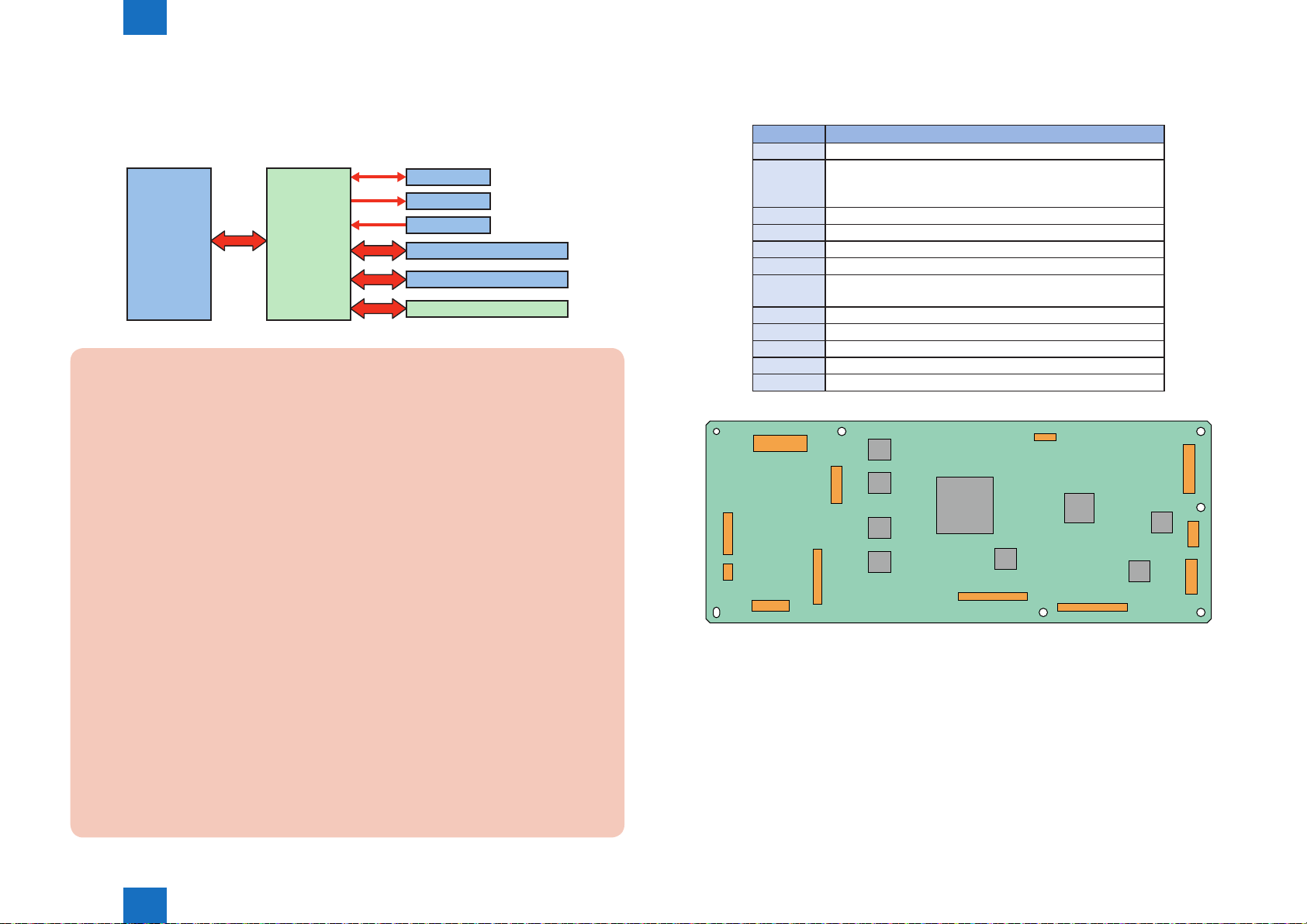
Reader controller PCB
■
Following is the function conguration of reader controller PCB.
Jack No. Destination
J101 Host machine (for power supply)
J102 DADF open/closed sensor 1 (SR1)
Scanner unit HP sensor (SR2)
DADF open/closed sensor 2 (SR3)
J103 Scanner unit exhaust fan (FM1)
J104 DADF driver PCB (for communication)
J105 Scanner unit (DADF)
J106 Scanner unit (Reader)
J107 Original size sensor 1 (CF1)
Original size sensor 2 (CF2)
J108 Scanner motor (M1)
J109 Main controller PCB (for communication)
J110 (Connection with PC)
J111 DADF driver PCB (for power supply)
J112 Scanner unit cooling fan (FM2)
J101
J110
J111
IC
J102
J103
J112
J104
J105
J106
T-2-2
J109
J108
J107
F-2-4
E490 (Error caused by incorrect DADF type)
-0001 If a not-supported DADF type is installed.
E473 (DDI communication error)
-0000, -0003, -0004
If the reader controller PCB detects communication error between the main controller PCB and
the reader controller PCB.
Technology > Basic conguration > Reader > Reader controller PCB
2
2-3
2
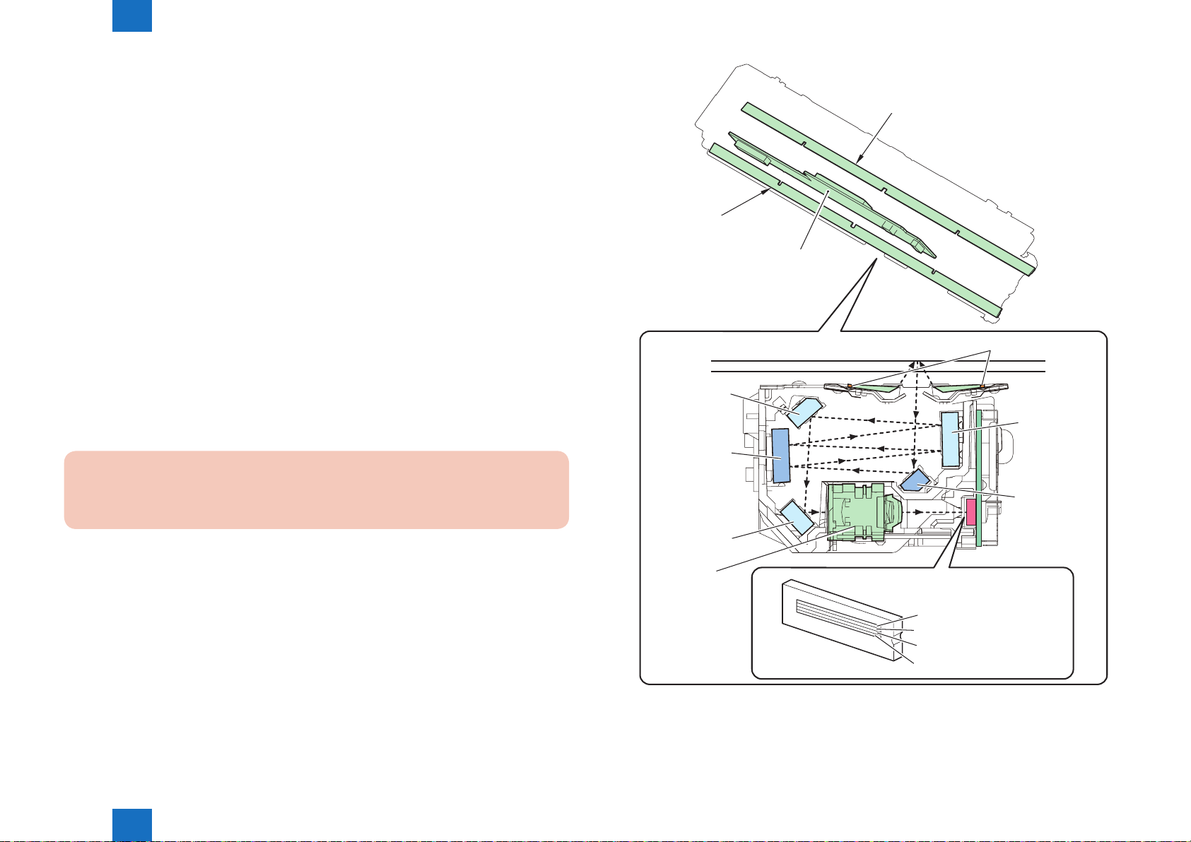
Technology > Basic conguration > Reader > Scanner unit
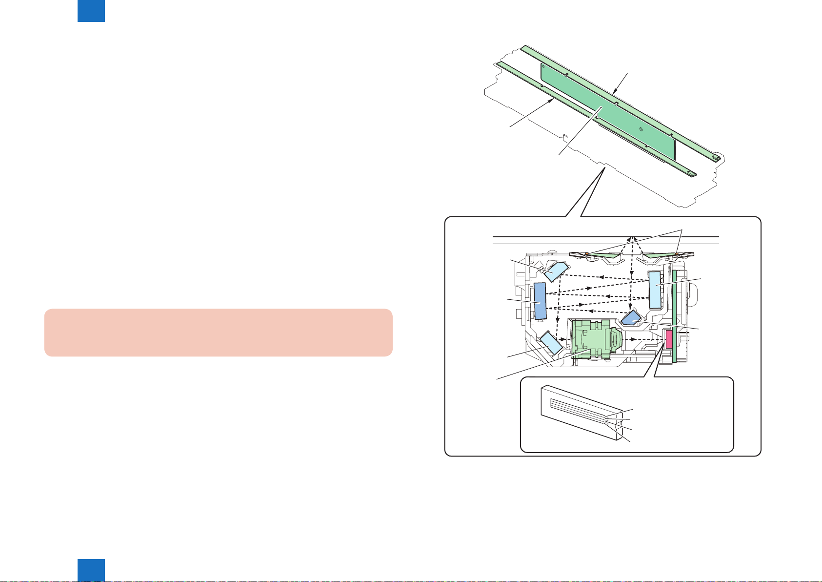
Scanner unit
■
Original exposure and scanning are performed by the integrated scanner unit of LED, mirror,
lens and reading sensor.
Light emitted from LED is reected by the original and reaches the reading sensor through
the 3 folding mirrors and 4 free curvature mirrors.
1. LED lamp unit
On LED lamp unit, the light is generated from the 2 LED lamp PCBs (LED chip: 54 pieces per
PCB).
Generated light is exposed to the original through the reection plate.
2. Free curvature mirror
Scanner unit is equipped with the 3 folding mirrors and 4 free curvature mirrors.
Free curvature mirror has symmetric facet in main scanning direction and asymmetric facet in
sub scanning direction against the optical axis.
2-4
Reader LED Lamp
PCB (Left)
Reader LED Lamp
PCB (Right)
Reader Scanner
Unit PCB
LED (light source)
3. Reading sensor
Reading sensor scans the image per 1image line.
Reading sensor has 4 lines (R, G, B, BW). At B&W scanning, it uses 1 line (B/W) and uses 3
lines (R, G, B) at color scanning.
Error code
E301 (insufcient light intensity)
-0001 The light intensity during front side shading is lower than the standard level
Mirror
No.4
Mirror
No.3
Mirror
No.2
Mirror
No.1
Mirror
No.5
Lens
CCD
[Red (R) line]
[Greeen (G) line]
[Blue (B) line]
[Black & white (B / W) line]
F-2-5
Technology > Basic conguration > Reader > Scanner unit
2
2-4
2
detection position
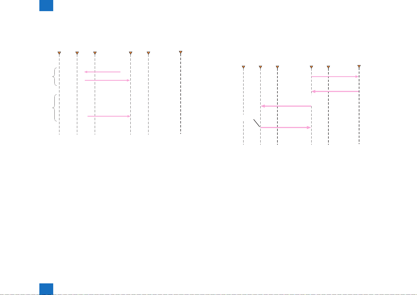
Technology > Basic conguration > Reader > Basic sequence
Basic sequence
■
Home position detection operation at power ON
●
Scan start
position
Stream
reading position
HPsensor
position
Shading
position
Image
leading edge
Original size
Original size detection operation
●
2-5
If the HP Sensor
is OFF when the
Main Power Switch
is ON
If the HP Sensor
is OFF when the
Main Power Switch
is ON
F-2-6
Scan start
position
30 sec timeout
HP search
operation
Stream
reading position
HP Sensor
position
Shading
position
Lamp ON
Lamp OFF
Image
leading edge
Copyboard is open
Original size
detection position
Copyboard is
closed
→Lamp ON
Original size
idntification
→Lamp OFF
F-2-7
Technology > Basic conguration > Reader > Basic sequence
2
2-5
2
detection position
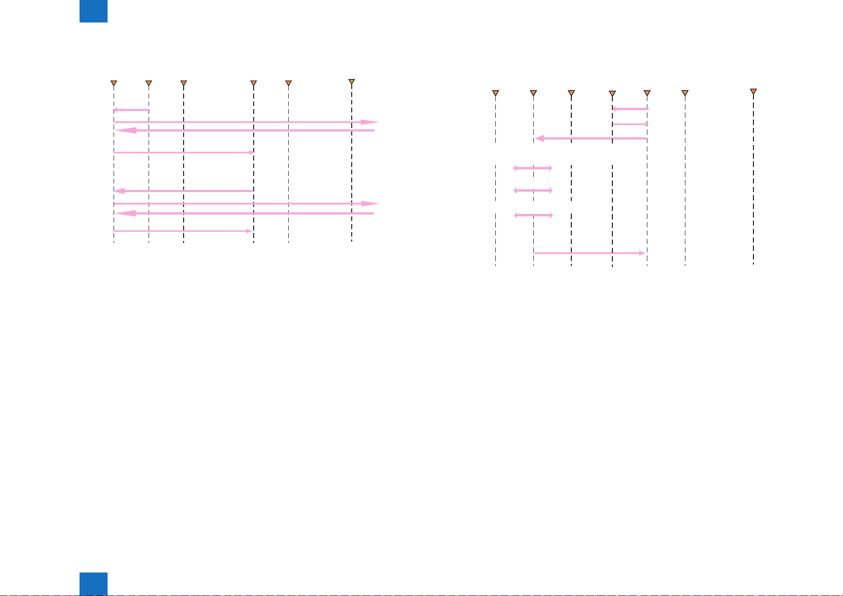
Technology > Basic conguration > Reader > Basic sequence
2-6
At start key ON (Book mode/1 sheet original)
●
Scan start
position
If the original
size detection
started before
the 30-second
time-out
HP search
operation
If the original
size detection
started after
the 30-second
time-out
HP search
operation
Stream
reading position
Lamp ON
HP sensor
position
position
Lamp ON
Shading
Image
leading edge
Original size
detection position
Reading
completed
・Stop
position
Lamp OFF
Reading
completed
・Stop
position
Lamp OFF
F-2-8
At start key ON (DADF mode/1 sheet original)
●
Scan start
position
Change in read position of the original in order to
avoid dust during stream reading(5points)
Stream reading dust detection(5points)
HP search
operation
Stream
reading position
Scan Operation
HP sensor
position
Shading
start
position
Lamp ON
Shading
position
Image
leading
edge
Original size
F-2-9
Technology > Basic conguration > Reader > Basic sequence
2
2-6
2
DADF driver PCB (PCB1)
Disengaging
motor 2 (M7)
Glass shifting
motor (M9)
Disengaging
motor 1 (M6)
Delivery
motor (M5)
Registration
motor (M3)
Read motor (M4)
Feed motor (M2)
Pickup roller unit
lifter motor (M10)
Tray lifter motor (M8)
Pickup motor (M1)
Scanner unit
cooling fan (FM3)
Scanner unit
Read motor Motor
cooling fan (FM2)
Motor driver cooling fan (FM1)
Original Display
LED PCB (LED1)
Delivery Display
LED PCB (LED2)
Disengaging
solenoid (SL1)
Stamp solenoid
(SL2)
Technology > Basic conguration > DADF > Parts Conguration
DADF
Function Conguration
■
Functions are listed below:
Reader controller PCB
Parts Conguration
■
List of Major Electric Parts
●
2-7
- Controls
- Power supply
assembly
assembly (front side)
Original feed
assembly
Original scanning
Original pickup
assembly
assembly (rear side)
DADF driver PCB
Original pickup tray assembly
Path of original Original delivery assemblyOriginal scanning
F-2-10
F-2-11
2
Technology > Basic conguration > DADF > Parts Conguration
2-7

2
Technology > Basic conguration > DADF > Parts Conguration
2-8
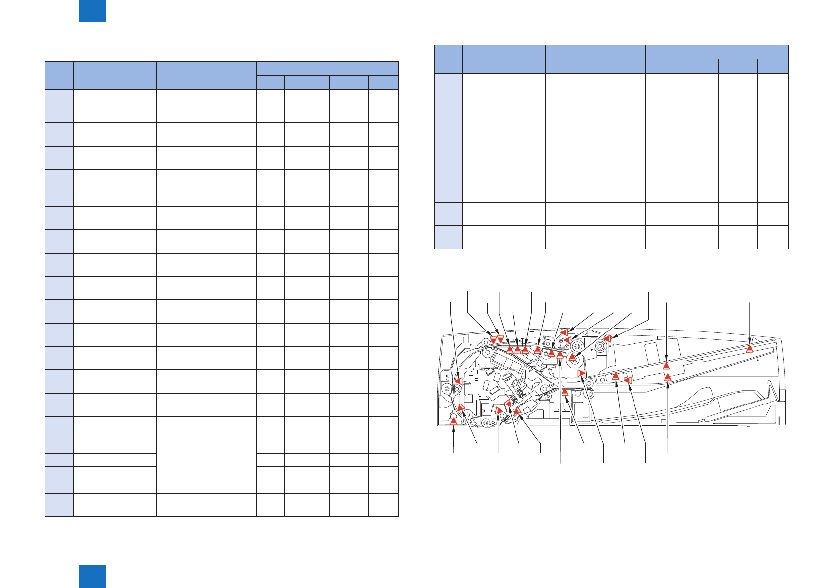
Drive Conguration
●
This equipment is a device to feed the original solely for stream scanning.
This equipment has 10 motors and 1 solenoid as drive load.
There is also 1 scanner unit for the original (for the back side).
Code Name Role Remarks
M1 Pickup motor Drive of pickup roller, separation roller, feed
roller 1
M2 Feed motor Drive of pullout roller, feed roller 2 Speed control is active
M3 Registration motor Drive of registration roller PS constant speed
M4 Read motor Drive of lead roller 1/2/3 and platen roller 1/2 PS constant speed
M5 Delivery motor Drive of delivery roller Speed control is active
M6 Disengagement
motor 1
M7 Disengagement
motor 2
M8 Tray lifter motor Up/down movement of pickup lifter -
M9 Glass shift motor Shift of glass of scanning assembly for back side -
M10 Pickup roller unit
lifter motor
SL1 Disengagement
solenoid
The drive of this equipment is shown below.
Disengagement of lead roller 1
(releasing pressure)
Disengagement of lead roller 2
(releasing pressure)
Up/down movement of pickup roller unit (using
cam)
Disengagement of delivery roller -
M2 M1
M10M9M3
Speed control is active
-
-
-
T-2-3
List of Rollers
●
[1]
[2]
[3]
[4]
[5]
[6]
[7]
[8]
[9]
[10]
[11]
[12]
[13]
[14]
[15]
[16]
[17]
[18]
[19] [20] [21] [22] [23]
[1] Pickup roller [14] Platen roller 1 wheel 1
[2] Feed roller 1 [15] Lead roller 2 wheel
[3] Separation roller [16] Lead roller 2
[4] Pullout roller wheel [17] Platen roller 2 wheel 1
[5] Pullout roller [18] Platen roller 2
[6] Feed roller 2 [19] Platen roller 2 wheel 2
[7] Feed roller 2 wheel [20] Lead roller 3 wheel
[8] Registration roller wheel [21] Lead roller 3
[9] Registration roller [22] Delivery roller wheel
[10] Lead roller 1 [23] Delivery roller
[11] Lead roller 1 wheel
[12] Platen roller 1 wheel 2
[13] Platen roller 1
F-2-13
M7
Technology > Basic conguration > DADF > Parts Conguration
2
SL1
M8M5M4M6
F-2-12
2-8
2
Technology > Basic conguration > DADF > Parts Conguration
Sensor List
●
Code Name Detection content
SR1 Original sensor Presence/absence of
original on original pickup
tray
SR2 Post-separation
sensor 1
SR3 Post-separation
sensor 2
SR4 Delay sensor Feed delay Yes Yes Yes -
SR5 Lead sensor 2 Disengaged timing of lead
SR6 Paper surface sensor Top surface position at
SR7 AB/ Inch identication
sensor
SR8 LTR-R/ LGL
identication sensor
SR9 Tray open/closed
sensor
SR10 Cover open/closed
sensor
SR11 Glass shifting HP
sensor
SR12 Pickup roller unit lifter
HP sensor
SR13 Tray HP sensor Most lowered position of
SR15 Disengaging HP
sensor 1
SR16 Disengaging HP
sensor 2
SR17 Original size sensor 1 Original size in width
SR18 Original size sensor 2 - - - -
SR19 Original size sensor 3 - - - -
SR20 Original size sensor 4 - - - -
SR22 Leading edge position
sensor
Leading edge of original
just after the pickup
Leading edge of original
just after the pickup
roller 2
original pickup
Identication of A4R/LTRR
and A5R/STMTR
Identication of LTR-R/LGL
Open/close of original
pickup tray
Open/close of feeder cover
Position of scanning glass
Position of pickup roller
unit
original pickup tray (upper)
Engaging/disengaging of
lead roller 1 wheel
Engaging/disengaging of
lead roller 2 wheel
direction
Leading edge position of
original at feeding
Delay Stationary Residue Others
- - - -
- - - Yes
- - - Yes
Yes Yes Yes -
- - - -
- - - -
- - - -
- - - -
- - - Yes
- - - -
- - - Yes
- - - -
- - - Yes
- - -
- - - -
- - Yes -
Jam detection
Yes
Code Name Detection content
PCB2 Post-separation
sensor 3
PCB3 Registration sensor - Registration arch creation
PCB4 Lead sensor 1 - Disengaging timing of
PCB5 Delivery sensor Disengaging timing of
VR Original width volume Original size in width
SR20
PCB3
SR15
SR22 SR17
SR18 SR19
SR5
PCB4
SR11
- Leading edge position
just after the pickup
- Original size in feed
direction
timing
- Disengaging timing of
lead roller 1
lead roller 1/2
- Original size in feed
direction
delivery roller
direction
PCB2
SR4
SR16
SR3
SR10
PCB5
SR12
SR9
SR2 SR7
SR1
SR13
2-9
Jam detection
Delay Stationary Residue Others
Yes Yes Yes Yes
Yes Yes Yes -
Yes Yes Yes -
Yes Yes Yes -
- - - -
T-2-4
SR6
SR8
VR
F-2-14
Technology > Basic conguration > DADF > Parts Conguration
2
2-9
2
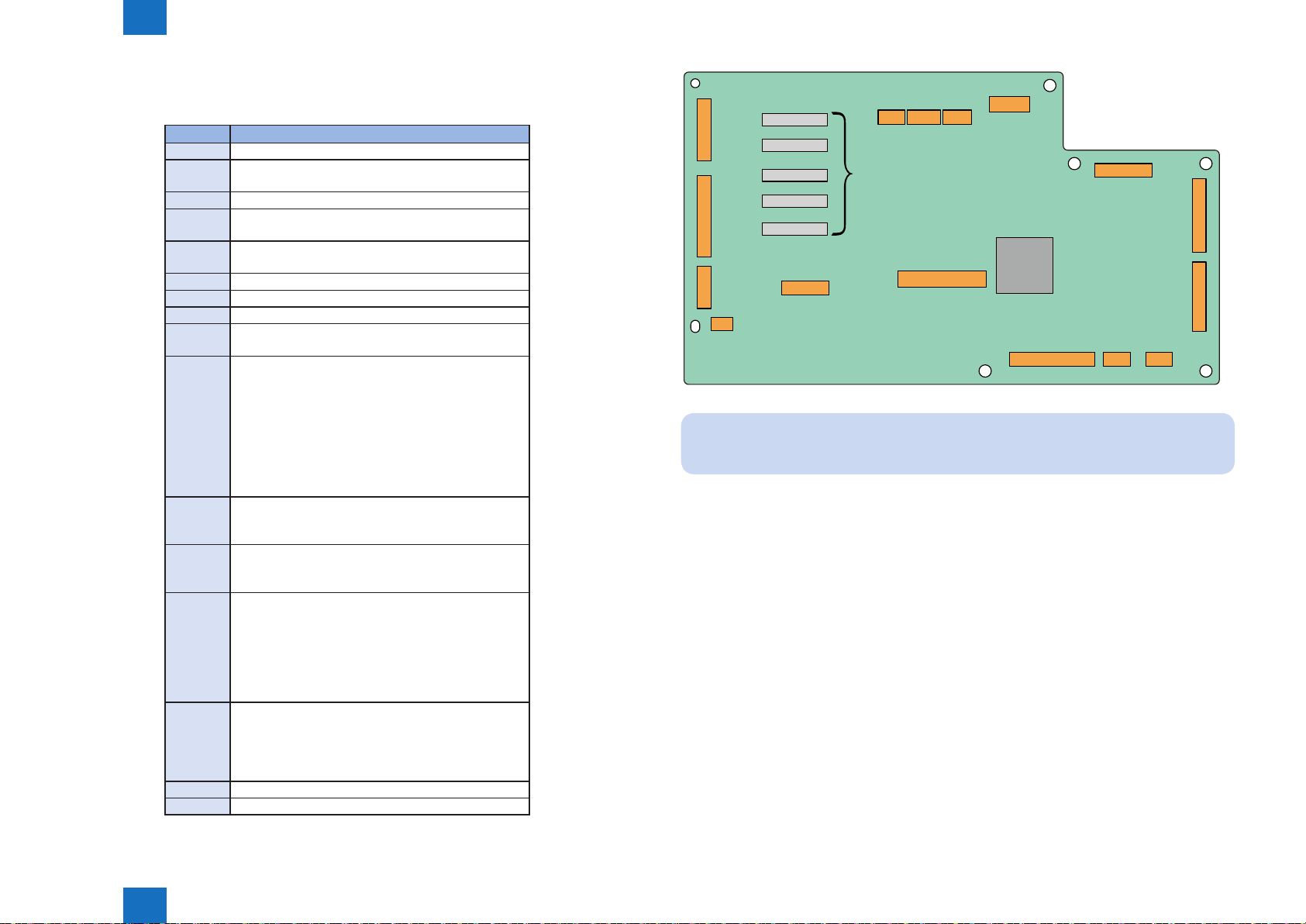
Technology > Basic conguration > DADF > DADF Driver PCB
DADF Driver PCB
■
Indicate the destination of the DADF driver PCB.
Jack No. Destination
J401 Reader controller PCB (for communication)
J402 Feed motor (M2)
Registration motor (M3)
J403 Pickup roller unit lifter motor (M10)
J404 Read motor cooling fan (FM2)
Motor driver cooling fan (FM1)
J405 Disengaging motor 1 (M6)
Disengaging solenoid (SL1)
J406 Pickup motor (M1)
J407 Read motor (M4)
J408 Delivery motor (M5)
J409 Disengaging motor 2 (M7)
Glass shifting motor (M9)
J410 Cover open/closed detection sensor (SR10)
Disengaging home position sensor 1 (SR15)
Original size sensor 1 (SR17)
Original size sensor 2 (SR18)
Original size sensor 3 (SR19)
Original size sensor 4 (SR20)
Leading edge position sensor (SR22)
Scanner unit cooling fan (FM3)
Original set display LED (LED)
J411 Lead sensor 2 (SR5)
Glass shifting home position sensor (SR11)
Disengaging home position sensor 2 (SR16)
J412 Registration sensor (PCB3)
Lead sensor 1 (PCB4)
Delivery sensor (PCB5)
J413 Post-separation sensor 1 (SR2)
Post-separation sensor 2 (SR3)
Delay sensor (SR4)
Paper surface sensor (SR6)
Tray open/closed sensor (SR9)
Pickup roller unit lifter home position sensor (SR12)
Post-separation sensor 3 (PCB2)
J414 Original sensor (SR1)
AB/ Inch identication sensor (SR7)
LTR-R/ LGL idencation sensor (SR8)
Tray home position sensor (SR13)
Original width volume (VR)
J416 Tray lifter motor (M8)
J418 Reader controller PCB (for power supply)
T-2-5
J403J408
J407
J416
Motor IC
J418
J402
J409
J405
IC
J406
J404
Note:
The scanner unit is connected to the reader controller PCB.
2-10
J401
J414
J413
J412J411J410
F-2-15
Technology > Basic conguration > DADF > DADF Driver PCB
2
2-10
2
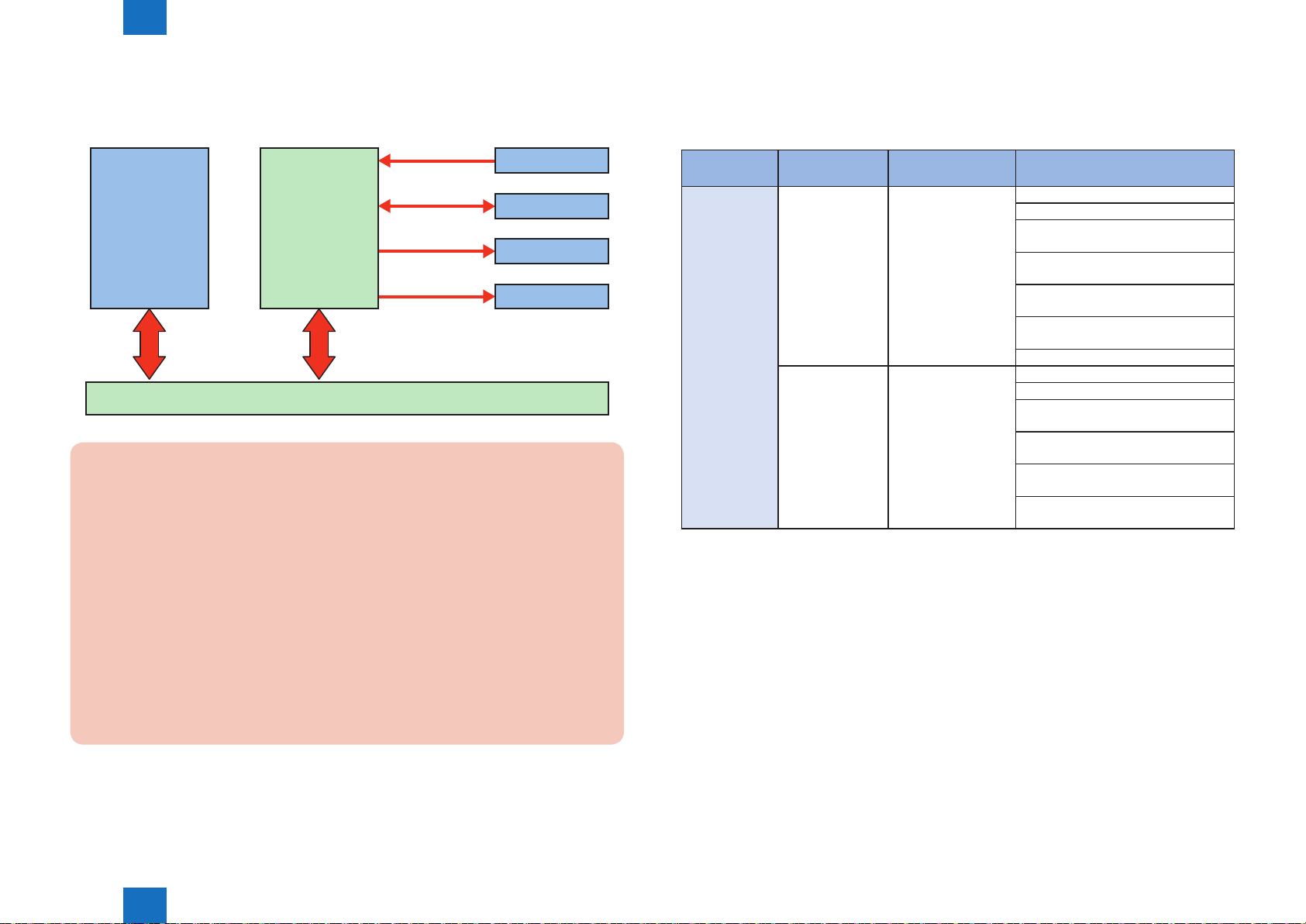
Technology > Basic conguration > DADF > Overview of Operation Mode
2-11
Electric Circuit Diagram
■
The control of this equipment is performed on the reader controller PCB.
Following shows the relation of each electrical parts.
Sensor
Scanner unit
Error code:
E270 (Error in the main scanning/sub scanning synchronization signal)
-0101 Sub scanning synchronization signal (VSYNC) is not properly transmitted from scanner
unit PCB (back side scanner unit), and this causes image failure or abnormal termination.
E280 (Communication error between reader controller PCB – scanner unit)
- 0101 If the communication is not started within the specied time between reader controller
PCB – back side scanner unit.
DADF driver
PCB
Reader controller PCB
Motor
Solenoid
Fan
F-2-16
Overview of Operation Mode
■
Overview
●
The operation mode of this equipment is classied as below.
Name of
operation mode
Normal rotation
pickup/delivery
The outline of the original ow is shown.
2-sided scanning
method
- Original is picked up
2-sided
simultaneous
scanning
Operation overview Applicable print mode
and is scanned by the
scanner unit in reader
side. And then, it is
delivered.
Original is picked up
and the front surface
is scanned by the
scanner unit in reader
side while back
surface is scanned
by the scanner unit in
DADF side.
And then, it is
delivered.
1-sided original -> 1-sided print
1-sided original -> 2-sided print
1-sided original with mix of same
conguration -> 1-sided print
1-sided original with mix of same
conguration -> 2-sided print
1-sided original with mix of different
conguration -> 1-sided print
1-sided original with mix of different
conguration -> 2-sided print
Extra long original -> 1-sided print
2-sided original -> 1-sided print
2-sided original -> 2-sided print
2-sided original with mix of same
conguration -> 1-sided print
2-sided original with mix of same
conguration -> 2-sided print
2-sided original with mix of different
conguration -> 1-sided print
2-sided original with mix of different
conguration -> 2-sided print
T-2-6
E400 (Communication error between reader controller PCB – DADF)
-0001 If check sum error occurs during communication between reader controller PCB - DADF.
-0002 If reception error occurs during communication between reader controller PCB - DADF.
E490 (Error caused by incorrect DADF type)
-0001 If a not-supported DADF type is installed.
Technology > Basic conguration > DADF > Overview of Operation Mode
2
2-11
2
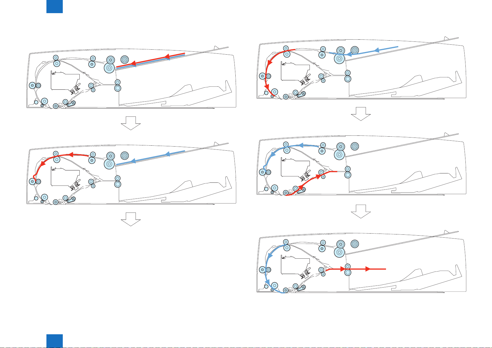
Technology > Basic conguration > DADF > Overview of Operation Mode
2-12
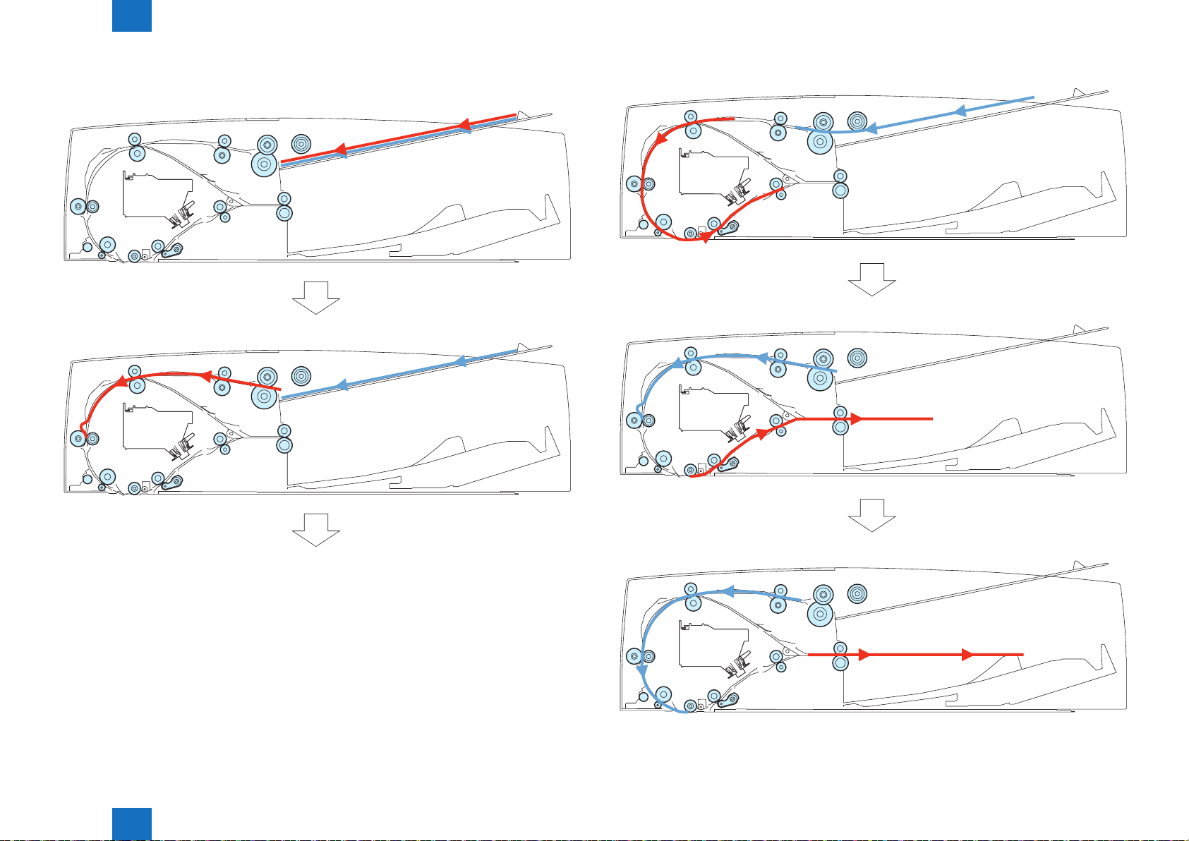
1-Sided Original (Small Size)
●
1) 1st side pickup
2) 1st side arch creation
3) 1st side feeding & 2nd side pickup
F-2-19
F-2-17
4) 2nd side arch creation
Technology > Basic conguration > DADF > Overview of Operation Mode
2
F-2-20
F-2-18
5) 2nd side scanning
F-2-21
2-12
2
Technology > Basic conguration > DADF > Overview of Operation Mode
2-13
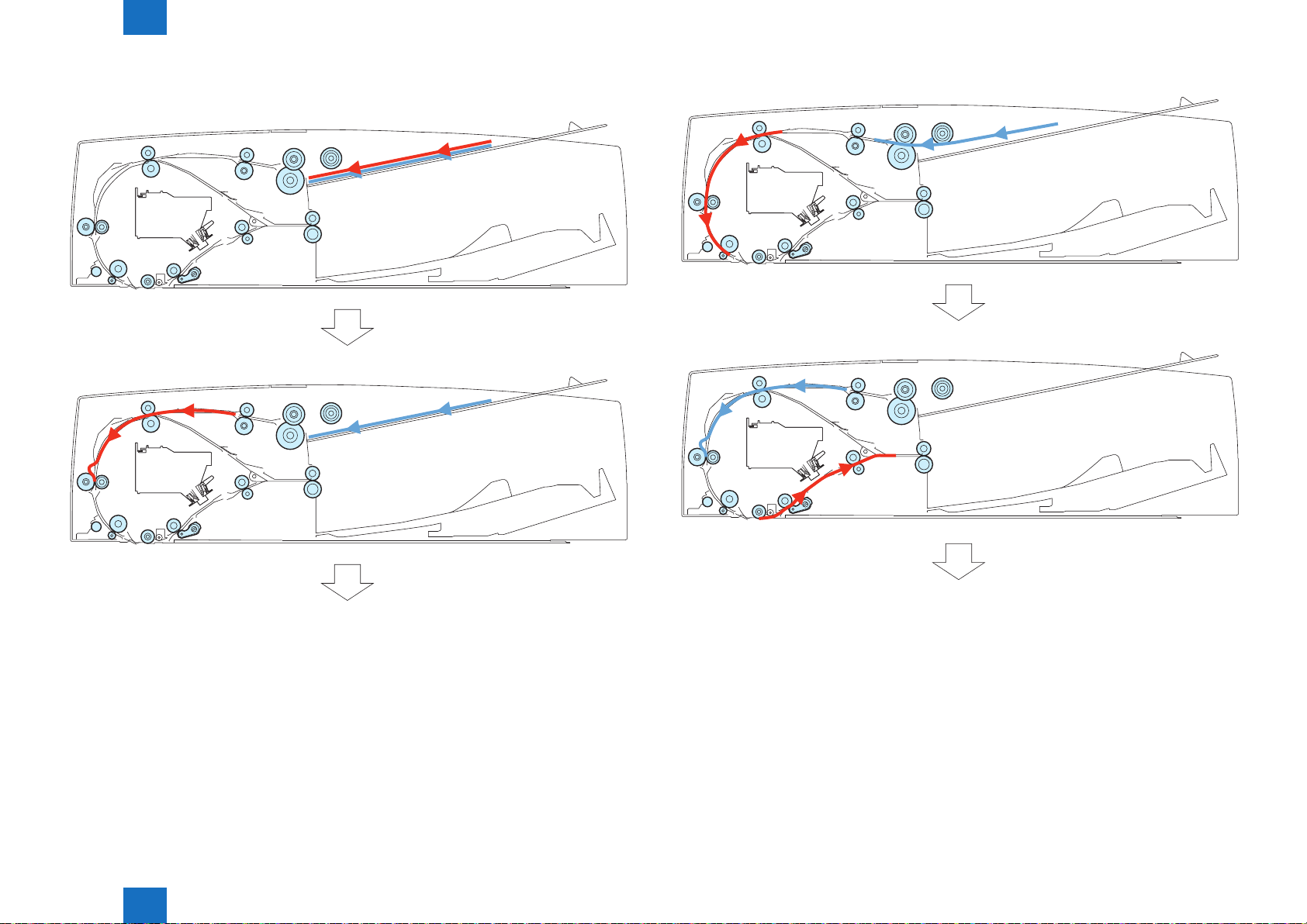
1-Sided Original (Large Size)
●
1) 1st side pickup
2) 1st side arch creation
3) 2nd side pickup
F-2-24
F-2-22
4) 2nd side arch creation
Technology > Basic conguration > DADF > Overview of Operation Mode
2
F-2-25
F-2-23
5) 2nd side scanning
F-2-26
2-13
2
Technology > Basic conguration > DADF > Overview of Operation Mode
2-14
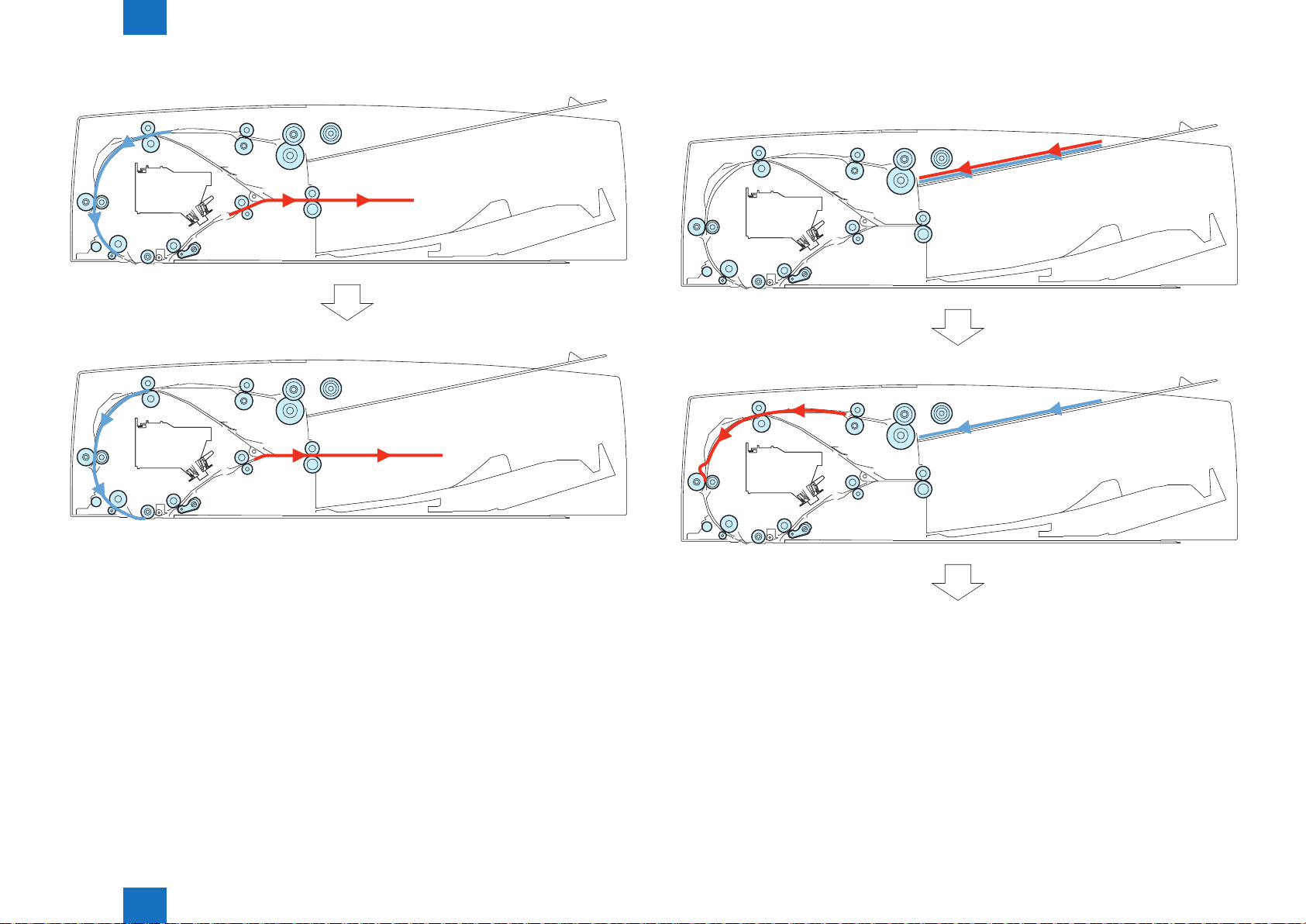
1-Sided Original with Mix of Same Conguration (Small Size)
●
1) 1st side pickup
2) 1st side arch creation
3) 1st side stop & 2nd side pickup
F-2-29
F-2-27
4) 2nd side arch creation
Technology > Basic conguration > DADF > Overview of Operation Mode
2
F-2-30
F-2-28
2-14
2
Technology > Basic conguration > DADF > Overview of Operation Mode
2-15
5) 2nd side stop (1st side is also stopped)
6) 2nd side scanning
F-2-31
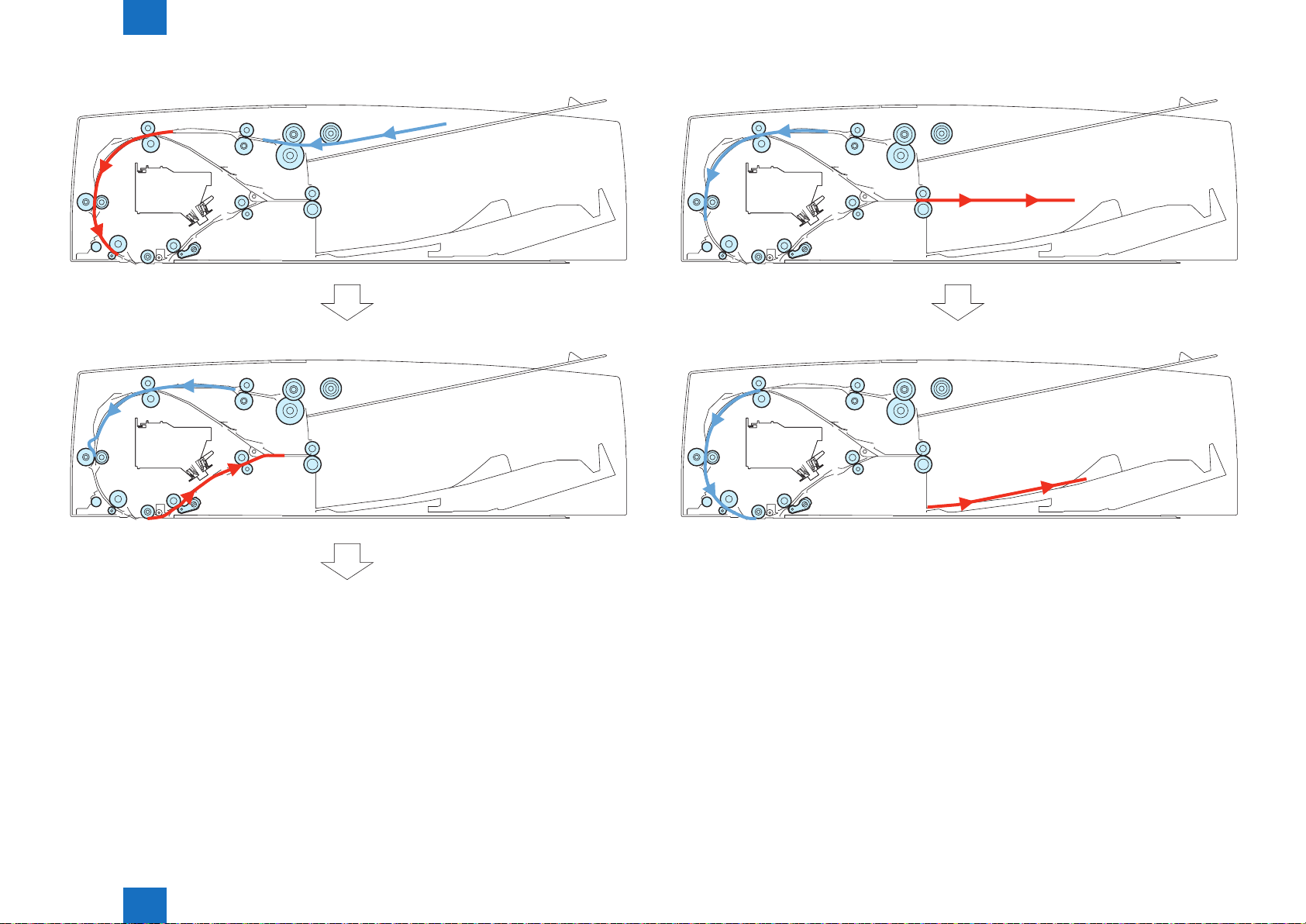
2-Sided Original (Simultaneous Scanning of Both Sides) (Small Size)
●
1) 1st side pickup
2) 1st side arch creation
F-2-33
Technology > Basic conguration > DADF > Overview of Operation Mode
2
F-2-32
F-2-34
2-15
2
Technology > Basic conguration > DADF > Overview of Operation Mode
2-16
3) 1st side feeding & 2nd side pickup
4) 2nd side arch creation
F-2-35
5) 2nd side feeding
F-2-37
6) 2nd side scanning
Technology > Basic conguration > DADF > Overview of Operation Mode
2
F-2-36
F-2-38
2-16
2
Technology > Basic conguration > DADF > Scanner Unit
Scanner Unit
■
For exposure and scanning of original, this equipment uses an integrated scanner unit
consists of the LED, the mirror, the lens and the reading sensor.
The light emitted from the LED is reected to the original, and then received by the reading
sensor through the 3 turndown mirrors and the 4 free curved mirrors.
a. LED lamp unit
The LED lamp unit emits light from 2 boards of LED lamp PCB (LED chip: 54 pc per board).
The emitted light is reected to the original through the reecting plate.
b. Free curved mirror
The scanner unit has 3 turndown mirrors and 4 free curved mirrors.
The free curved mirror is a mirror symmetric to the light shaft in main (horizontal) scanning
direction while dissymmetric in sub (vertical) scanning direction.
c. Reading sensor
The reading sensor performs scanning of image per image line.
The reading sensor has 4 lines (B/W, R, G, B), using 1 line (B/W) when scanning black/white
image and 3 lines (R, G, B) when scanning color image.
Error code
E301 (insufcient light intensity)
-0101 The light intensity during back side shading is lower than the standard level
2-17
DADF LED Lamp
PCB (Left)
DADF LED Lamp
PCB (Right)
DADF Scanner
Unit PCB
LED (light source)
Mirror
No.4
Mirror
No.3
Mirror
No.2
Mirror
No.1
Technology > Basic conguration > DADF > Scanner Unit
2
Mirror
No.5
Lens
CCD
[ Red (R) line]
[ Greeen (G) line]
[ Blue (B) line]
[ Black & white (B / W) line]
F-2-39
2-17
Loading...