


rh-918a
Table of contents
 Loading...
RH-981A
ELECTRONIC EYELET BUTTON HOLER
ENGLISH
RH-981A
i
Thank you very much for buying a BROTHER sewing machine. Before using your new machine, please read the safety
instructions below and the explanations given in the instruction manual.
With industrial sewing m achines, it is norm al to carr y out work while posit ioned direct ly in front of m oving parts suc h as
the needle and thread tak e-up lever, and consequently there is a lways a danger of injury that can be caused by these
parts. Follow the instructions from training personnel and instructors regarding safe and correct operation before
operating the machine so that you will know how to use it correctly.
SAFETY INSTRUCTIONS
1.
Safety indications and their meanings
This instruction m anual and the indications and s ymbols that are used on the mac hine itself are provided in order to
ensure safe operation of this machine and to prevent accidents and injury to yourself or other people.
The meanings of these indications and symbols are given below.
Indications
DANGER
The instructions which follo w this term indic ate situations where f ailure to f ollow the
instructions will almost certainly result in death or severe injury .
CAUTION
The instructions which follo w this term indic ate situations where f ailure to f ollow the
instructions could cause injury when using the machine or physical damage to
equipment and surroundings.
Symbols
........................................This symbol ( ) indicates something that you should be careful of. The
picture inside the triangl e indic ates t he na ture of the caution that m ust be
taken.
(For example, the symbol at left means “beware of injury”.)
........................................This symbol (
) indicates something that you must not do.
........................................This symbol ( ) indicates something that you must do. The picture
inside the circle indicates the nature of the thing that must be done.
(For example, the symbol at left means “you must make the ground
connection”.)
RH-981A
ii
2.
Notes on safety
DANGER
Wait at least 5 minutes after turnin
g
off the
p
ower switch and disconnectin
g
the
p
ower cord from the wall outlet
before o
p
enin
g
the face
p
late of the control box. Touchin
g
areas where hi
g
h volta
g
es are
p
resent can result in
severe injury.
CAUTION
Environmental requirements
Use the sewing machine in an area which is f ree
from sources of stron
g
electrical noise such as
high-frequency welders.
Sources of stron
g
electrical noise ma
y
cause
problems with correct operation.
Any fluctuations in the power supply voltage
should be within
10% of the rated voltage for
the machine.
Voltage fluctuations which are greater than this
may cause problems with correct operation.
The
p
ower su
pp
l
y
ca
p
acit
y
should be
g
reater than
the re
q
uirements for the sewin
g
machine’s
electrical consumption.
Insufficient
p
ower su
pp
l
y
ca
p
acit
y
ma
y
cause
problems with correct operation.
The
p
neumatic deliver
y
ca
p
abilit
y
should be
g
reater than the re
q
uirements for the sewin
g
machine's total air consumption.
Insufficient
p
neumatic deliver
y
ca
p
abilit
y
ma
y
cause problems with correct operation.
The ambient tem
p
erature should be within the
range of 5 to 35 during use.
Tem
p
eratures which are lower or hi
g
her than this
may cause problems with correct operation.
The relative humidit
y
should be within the ran
g
e of
45% to 85% durin
g
use, and no dew formation
should occur in any devices.
Excessivel
y
dr
y
or humid environm ents and dew
formation ma
y
cause
p
roblems with correct
operation.
Avoid exposure to direct sunlight during use.
Ex
p
osure to direct sunli
g
ht ma
y
cause
p
roblems
with correct operation.
In the event of an electrical storm, turn off the
p
ower and disconnect the
p
ower cord from the
wall outlet.
Li
g
htnin
g
ma
y
cause
p
roblems with correct
operation.
Installation
Machine installation s hould onl
y
be carried out b
y
a qualified technician.
Contact your Brother dealer or a qualified electrician
for any electrical work that may need to be d one.
The sewin
g
machine wei
g
hs more than 87 k
g
.
The installation should be carried out b
y
two or
more people.
Do not connect the
p
ower cord until installation is
com
p
lete, otherwise the machine m a
y
o
p
erate if
the start swit ch is
p
ressed b
y
mistake, which could
result in injury.
Be sure to connect the
g
round. If the
g
round
connection is not secure, you run a high risk of
receiving a serious electric shock, and problem s
with correct operation may also occur.
All cords should be secured at least 25 mm awa
y
from an
y
movin
g
p
arts. Furthermore, do not
excessivel
y
bend the cords or secure them too
firml
y
with sta
p
les, otherwise there is the dan
g
er
that fire or electric shocks could occur.
Install the belt covers to the machine head and
motor.
If usin
g
a work table which has casters, the
casters should be secured in such a wa
y
so that
they cannot move.
Be sure to wear
p
rotective
g
o
gg
les and
g
loves
when handlin
g
the lubricatin
g
oil and
g
rease, so
that the
y
do not
g
et into
y
our e
y
es or onto
y
our
skin, otherwise inflammation can result.
Furthermore, do not drink the oil or eat the
g
rease
under an
y
circumstances, as the
y
can cause
vomiting and diarrhoea.
Keep the oil out of the reach of children.
RH-981A
iii
CAUTION
Sewing
This sewing machine should only be used by
operators who have received the necessary
training in safe use beforehand.
The sewin
g
machine should not be us ed for an
y
applications other than sewing.
Be sure to wear
p
rotective
g
o
gg
les when usin
g
the
machine.
If goggles are not worn, there is the d anger that if
a needle breaks,
p
arts of the broken needle ma
y
enter your eyes and injury may result.
Turn off the power switch at the foll owing times,
otherwise the machine ma
y
o
p
erate if the start
switch is
p
ressed b
y
mistake, which could result in
injury.
When threading the needle
When replacing the needle
When not usin
g
the machine and when leavin
g
the machine unattended
If usin
g
a work table which has casters, the
casters should be secured in such a wa
y
so that
they cannot move.
Attach all safet
y
devices before usin
g
the sewin
g
machine. If the machine is used without these
devices attached, injury may result.
Do not touch an
y
of the movin
g
p
arts or
p
ress an
y
ob
j
ects a
g
ainst the machine while se win
g
, as this
ma
y
result in
p
ersonal in
j
ur
y
or dama
g
e to the
machine.
If an error occurs in machine o
p
eration, or if abno rmal
noises or smells ar e not ice d, im medi atel
y
turn off the
p
ower switch. Then contact
y
our nearest Brother
dealer or a qualified technician.
If the machine develo
p
s a
p
roblem, contact
y
our
nearest Brother dealer or a qualified technician.
Cleaning
Turn off the
p
ower switch before carr
y
in
g
out
cleaning, otherwise the machine may operate if
the start swit ch is
p
ressed b
y
mistake, which could
result in injury.
Be sure to wear
p
rotective
g
o
gg
les and
g
loves
when handlin
g
the lubricatin
g
oil and
g
rease, so
that the
y
do not
g
et into
y
our e
y
es or onto
y
our
skin, otherwise inflammation can result.
Furthermore, do not drink the oil or eat the
g
rease
under an
y
circumstances, as the
y
can cause
vomiting and diarrhoea.
Keep the oil out of the reach of children.
Maintenance and inspection
Maintenance and inspection of the sewing
machine should only be carried out b y a qualified
technician.
Ask your Brother dealer or a qualified electrician to
carry out any maintenance and inspecti on of the
electrical system.
Turn off the power switch and disconnect the
power cord from the wall outlet at the following
times, otherwise the m achine may operate if the
start switch is pressed by mistake, which could
result in injury.
When carrying out inspection, adj ustment and
maintenance
When replacing consum able par ts such as the
loopers and knife
Disconnect the air hoses from the air supply and
wait for the needle on the pres sure gauge to dr op
to “0” before carrying out inspection, adjustment
and repair of any parts which use the pneumatic
equipment.
If the power switch and air need to be left on when
carrying out some adjustment, be extremely
careful to observe all safety precautions.
Use only the proper replacement parts as
specified by Brother.
If any safety devices have been removed, be
absolutely sure to re-install them to their original
positions and check that they operate correctly
before using the machine.
Any problems in machine operation which result
from unauthorized modifications to the machine
will not be covered by the warranty.
RH-981A
iv
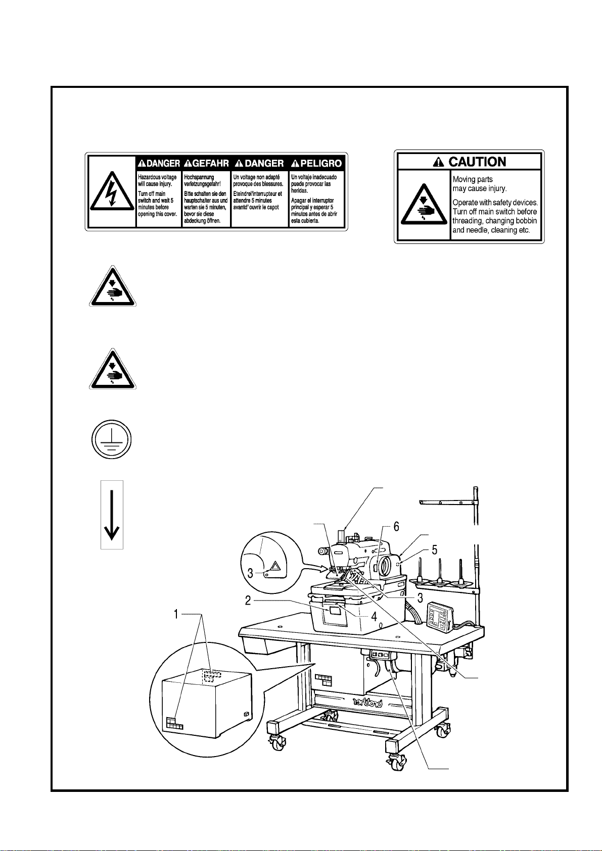
Finger guard
3. W a rnin g lab e ls
The following warning labels appear on the sewing machine.
Please follow the in str uc tions on the labe ls at a ll t imes when using the machine. If the labels hav e bee n removed
or are difficult to read, please contact your nearest Brother dealer.
Safety devi ces
Eye guard
Finger guard
Needle bar guard
Belt cover, etc.
3
Do not touch the knif e or press any objects
against the machine while sewing, as this
may result in personal injury or damage to
the machine.
5
Be sure to connect the ground. If the ground connection is not secure, you run a high risk o
f
receiving a serious electric shock, and problems with correct operation may also occur .
6
Direction of operation
3122Q
1
2
Belt cover
Needle bar guard
Eye guard
Belt cover
(Rear)
4
Be careful not to clamp your fingers when
closing the front cover.

RH-981A
CONTENTS
1. NAMES OF EACH P A RT
................................ 1
2. SPECIFICATIONS
.............................................. 2
2-1. Specifications ...................................................... 2
2-2. Sewing shape ..................................................... 3
2-3. Optional parts ...................................................... 3
2-4. PD-9810, Programmer ....................................... 3
2-5. Replacement parts list for
specification changes ......................................... 4
3. INST ALLATION
.................................................... 5
3-1. Table processing diagram ................................ 5
3-2. Installing the motor ............................................ 6
3-3. Installing the motor pulley ................................. 7
3-4. Installing the control box ................................... 7
3-5. Installing the machine head .............................. 8
3-6. Installing the oil container ............................... 10
3-7. Installing the operation panel .......................... 10
3-8. Tightening the V-belt ....................................... 11
3-9. Installing the spool stand ................................ 12
3-10.Installing the hand switch ................................ 12
3-11.Installing the air unit and the valve unit .......... 12
3-12.Connecting the wiring...................................... 13
3-12-1. Connections inside the control box......... 14
3-12-2. Connecting the motor cables................... 15
3-12-3. Connecting the air tubes.......................... 15
3-12-4. Securing the cables.................................. 16
3-13.Connecting the air tubes ..................................17
3-13-1. Adjusting the air pressure........................ 17
3-14.Connecting the power cord ............................. 18
3-15.Installing the programmer
(sold separately)............................................... 19
3-16.Installing the foot switch (option)..................... 19
3-17.Installing the indexer (option) .......................... 20
3-17-1. Installing the indexer main unit................ 20
3-17-2. Installing the upper thread presser ......... 21
3-17-3. Replacing the plate presser and
presser plate ............................................ 21
3-17-4. Installing the valve unit ................................ 21
3-17-5. Connecting the connectors.......................... 22
3-17-6. Connecting the air tubes ............................. 23
3-17-7. Securing the air tubes and cables............... 23
3-17-8. Installing the hand switch............................. 24
4. LUBRICATION
...................................................... 25
4-1. Adding oil ......................................................... 25
4-2. Lubrication ....................................................... 25
5. CORRECT USE
................................................. 27
5-1. Data initialization............................................... 27
5-2. Changing the lower thread and
gimp trimming .................................................. 27
5-3. Installing the needle ......................................... 28
5-4. Threading the upper thread ............................. 28
5-5. Threading the lower thread.............................. 29
5-6. Threading the gimp ......................................... 30
5-7. Setting the material .......................................... 31
5-8. Setting the installation position
for cloth feed plate (L) (-52 specifications)...... 33
5-9. Replacing the PROMs ..................................... 34
6. OPERATION
......................................................... 35
6-1. Name and function of
each operation panel item................................ 35
6-2. Starting up......................................................... 36
6-3. Program setting method .................................. 37
6-3-1. Parameter table ( Taper bar )..................... 37
6-3-2. Parameter table ( Straight bar tacking )......40
6-4. Cy cle program.................................................. 43
6-5. Production counter ........................................... 44
6-6. Using the program memos.............................. 44
7. SEWING
................................................................ 45
7-1. Automatic sewing............................................. 45
7-2. Using the EMERGENCY STOP switch ......... 46
7-3. Adjusting the thread tension ............................ 47
7-4. Needle and knife position................................. 48
7-5. Setting the feed bracket to
the front position............................................... 49
7-6. Switching between single-pedal
and dual-pedal operation ................................. 49
7-7. Using test feed mode....................................... 50
7-8. Using manual mode......................................... 51
7-9. Changing the mode during an operation ........ 52
7-10.Moving the cloth feed bar
(-52 specifications) ........................................... 52
8.
CLEANING AND MAINTENANCE
............
53
8-1. Cleaning ........................................................... 53
8-2. Draining the oil ................................................. 54
8-3. Checking the air filter........................................ 54
9. STANDARD ADJUSTMENTS
....................... 55
9-1. Adjusting the height of the
spreader and looper......................................... 55
9-2. Adjusting the needle and looper timing........... 56
9-3. Adjusting the loop stroke.................................. 57
9-4. Adjusting the height of the needle bar............. 58

RH-981A
9-5. Adjusting the clearance between the
looper and needle ............................................ 58
9-6. Adjusting the needle guard.............................. 59
9-7.
Adjusting the spreader mounting positions
........ 59
9-8. Adjusting the spreader timing.......................... 60
9-9. Adjusting the needle racking width
(stitch width)...................................................... 60
9-10.Changing the knife cutting length
(Replacing the hammer).................................. 61
9-11.Adjusting the contact between the knife
and the hammer .............................................. 62
9-12.Replacing the knife .......................................... 63
9-13.
Adjusting the cutting pressure ........................ 63
9-14.
Adjusting the position of the work
clamp plate ........................................................64
9-15.
Adjusting the cloth opening amount ............... 65
9-16.
Adjusting the trimming
of the upper thread .......................................... 66
9-17.Adjusting the trimming
of the lower thread and gimp .......................... 66
9-18.Adjusting the gimp length after trimming
(-02, -52 specifications) ................................... 67
9-19.Lower thread presser
(-02
, -52
specifications) .................................... 67
9-20.Auxiliary clamp arm
(-02, -52 specifications).................................... 68
9-21.Adjusting the cloth feeding speed
(-52 specifications) ........................................... 68
9-22.Adjusting the cloth feed bar home position
(-5 2 s pe ci fi cat io ns )............................................. 69
9-23.Adjusting the indexer hole spacing
(-52 specifications) ........................................... 70
9-24.Adjusting the position of limit switch L
(-52 specifications) .......................................... 71
9-25.Adjusting the position of limit switch R
(-52 specifications) .......................................... 71
10. CHANGING FUNCTIONS USING
THE MEMORY SWITCHES
........................ 72
10-1.Memory switch table ........................................ 73
11. CHA NGING FUNCTIONS USING
THE DIP SWITCHES
.................................... 74
11-1. Panel DIP switches....................................... 74
11-2. Circuit board DIP switches............................ 75
12. LIST OF ERROR CODES
............................ 77
13. TROUBLESHOOTING
................................... 80
1. NAMES OF EACH PART
RH-981A
1
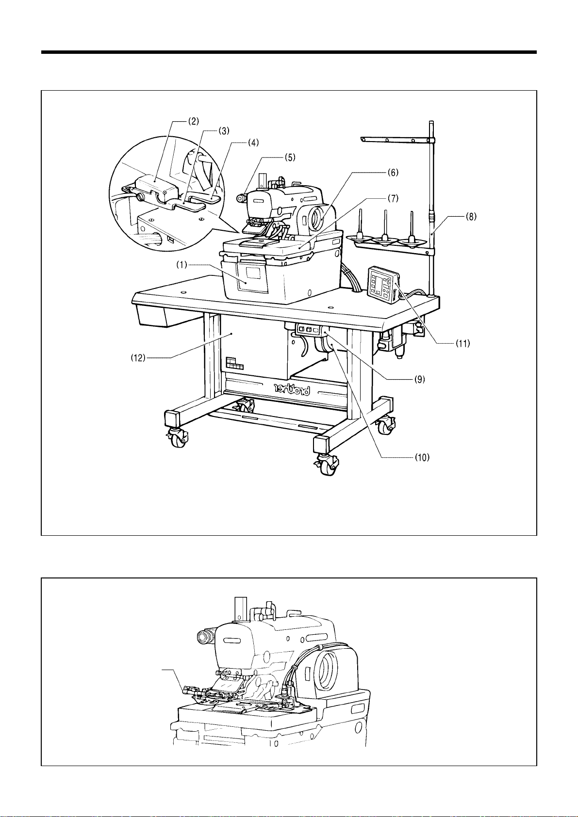
1. NAMES OF EACH PART
(1) Front cover (2) Hand switch (3) Cloth presser switch (4) Start switch
(5) EMERGENCY STOP switch (6) Upper shaft pulley (7) Feed bracket (8) Spool stand
(9) Power switch (10) Motor (11) Operation panel (12) Control box
Fly indexer (-52 specifications)
3123Q
Fly indexer
2380Q

2. SPECIFICATIONS
RH-981A
2
2. SPECIFICATIONS
2-1. Specifications
Specification RH-981A-00 RH-981A-01 RH-981A-02, RH-981A-52
Application Men’s clothes and ladies’ clothes Jeans and work clothes
Sewing speed 1,000 - 2,200rpm (100-rpm steps)
Stitch length 5 - 50 mm 5 - 38 mm
L1 14 - 18 mm L5 28 - 32 mm
L2 18 - 22 mm L6 32 - 36 mm
L3 22 - 26 mm L7 36 - 40 mm
L4 26 - 30 mm
Stitch pitch 0.5 - 2.0 mm
Stitch width 1.5 - 3.2 mm
Tacking length 0 - 20 mm
Work clamp height 12 mm 16 mm
Starting method Dual switch (cloth presser switch and start switch) or single switch
Feed method
Intermittent feed by three pulse motors (X, Y, θ)
Needle DO X 558 Nm 80 - Nm 120 (Schmetz 558)
Safety equipment
Built-in emergency stop function and automatic stopping device which stops the machine
when the safety circuit is activated
Motor Inverter-type induction motor
Air pressure
Main regulator: 0.5MPa
Knife pressure regulator: 0.3MPa
Air consumption 43.2 l/ min. (8 cycles/min.)
Noise level 85dB at max. speed of 2,200r pm, measured according to ISO 10821
Dimensions 1,200 mm (W) X 590 mm(D) X 1,120 mm (H)
Work table legs T-shape height-adjustable type
Power supply
Single-phase 220 V
3-phase 220 V, 380 V, 400 V
Maximum electric power consumption: 1kvA
Weight 163.5 kg
Fly indexer specifications (-52 specifications)
Standard Large size
Max. hole spacing
50.8 mm
(2 inch)
57.15 mm
(2 1/4 inch)
Max. overall feed amount
152.4 mm
(2 inch X 3)
285.75 mm
(2 1/4 inch X 5)
No. of holes 3 - 4*
1
3 - 6*
1
Horizontal sewing margin 9 - 21 mm (9 - 11 mm*
2
)
Vertical sewing margin 30 - 40 mm
*1 The cloth feed bar F assembly (sold separately) can be
processed and used so that 1 to 9 buttonholes can be sewn.
*2 L5 - L7 specifications
Hole spacing
0792Q
Vertical sewing
margin
Horizontal
sewing
margin
No. of holes
Overall feed amount
Lower thread trimmer
Upper thread trimmer
Long type Short type
Fly indexer
-00 -- -
-01 --
-02 - -
-52 -
* -02 and -52 specifications are further divided into L1 - L7
specifications in accordance with the stitch lengt h. Please be sur e
to specify the stitch length when ordering.
2. SPECIFICATIONS
RH-981A
3
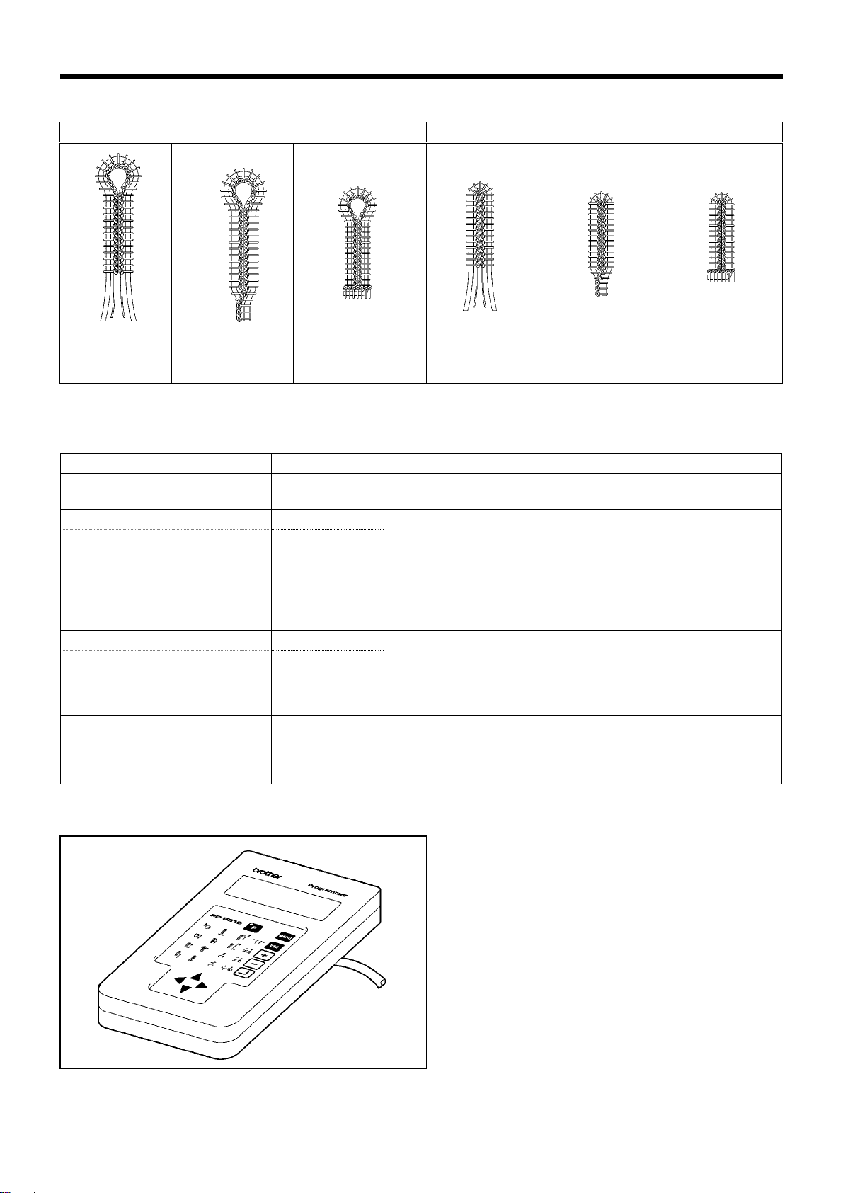
2-2. Sewing shape
Eyelet buttonhole Straight buttonhole
Without bar
tacking
With taper With straight bar
tacking (*)
Without bar
tacking
With taper With straight bar
tacking (*)
* The DIP switch settings must be changed. (Refer to page 74.)
2-3. Optional parts
Parts name Parts code
Two-pedal foot switch S42838-101
This allows the work clamp to raised and lowered and the
sewing machine to be started by pedal operation.
Waist belt presser
Cloth presser (L3W) set
Cloth presser (L4W) set
S43701-001
S43704-001
When sewing eyelet buttonholes into wa ist belts with which
have differences in thickness, this presser provides secure
clamping for the differ ent thickness. It prevents an y slippage
of the material during sewing.
Upper thread nipper
S43406-301
This device prevents the thread from pulling out at the sewing
start, thus contributing to a m ore accurate and higher-qual ity
seam finish.
Fly indexer
Fly indexer assembly for L1, L2
and L5 specification s
Fly indexer assembly for L3, L4,
L6 and L7 specification s
S44279-101
S44281-101
This is an indexer which is specially for use when sewing flys.
It allows from one to nine buttonholes to be set, and
automatically feeds the mater ial. Using this de vic e makes the
sewing of buttonholes for flys much quicker.
Special lapel cutting dev i ce
S53906-201
Eyelet buttonhole and straight buttonhole can be sewn
automatically without replacing hammer and knife. It is
effective for men’s jacket cycle sewing (eyelet buttonhole-
flower hole).
2-4. PD-9810, Programmer
You can use the icon keys to retrieve p arameter s at a
single touch, and to displa y them as ic ons on the LED
screen so that the settings can be changed easil y. It
allows you to easily transfer data between different
sewing machines.
2381
Q
2. SPECIFICATIONS
RH-981A
4
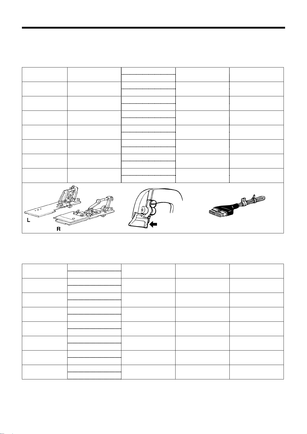
2-5. Replacement parts list for specification changes
The sewing machine can be cha nged to an y one of L1 - L7 f or - 02 and -52 specif icatio ns by rep lacing the s pecif ied
parts with the appropriate parts given below.
-02 specifications
Plate R assemblySpecifications
(buttonhole length)
Replacement parts set
Plate L assembly
Hammer Specification harnes s
S38576-301 S37702-001 (S12)L1
(14 - 18 mm)
S44238-001
S38577-201 S37704-001 (S16)
S43337-000
S38578-301 S37704-001 (S16)L2
(18 - 22 mm)
S44239-001
S38579-201 S37706-001 (S20)
S43338-000
S38580-301 S37706-001 (S20)L3
(22 - 26 mm)
S44240-001
S38581-201 S37708-001 (S24)
S43339-000
S38582-301 S37708-001 (S24)L4
(26 - 30 mm)
S44271-001
S38583-201 S42053-001 (S28)
S43340-000
S41470-101 S37197-001 (26)L5
(28 - 32 mm)
S44272-001
S41471-101 S37199-001 (30)
S43341-000
S41472-101 S37199-001 (30)L6
(32 - 36 mm)
S44273-001
S41473-101 S37201-001 (34)
S43342-000
S41474-101 S37201-001 (34)L7
(36 - 40 mm)
S44274-001
S41475-101 S35093-001 (38)
S43343-000
Note: There is 10 mm of difference in the knife cutting position between L1 - L4 and L5 - L7 specifications. (Refer to
page 63.)
-52 specifications
Plate R assemblySpecifications
(buttonhole length)
Plate L assembly
Hammer Specification harness Cloth feed plate R
S38576-301 S37702-001 (S12)L1
(14 - 18 mm)
S38577-201 S37704-001 (S16)
S43360-000 S43809-001
S38578-301 S37704-001 (S16)L2
(18 - 22 mm)
S38579-201 S37706-001 (S20)
S43361-000 S43809-001
S38580-301 S37706-001 (S20)L3
(22 - 26 mm)
S38581-201 S37708-001 (S24)
S43362-000 S42139-101
S38582-301 S37708-001 (S24)L4
(26 - 30 mm)
S38583-201 S42053-001 (S28)
S43363-000 S42139-101
S41470-101 S37197-001 (26)L5
(28 - 32 mm)
S41471-101 S37199-001 (30)
S43364-000 S43809-001
S41472-101 S37199-001 (30)L6
(32 - 36 mm)
S41473-101 S37201-001 (34)
S43365-000 S42139-101
S41474-101 S37201-001 (34)
L7
(36 - 40 mm)
S41475-101 S35093-001 (38)
S43366-000 S42139-101
Note: There is 10 mm of differenc e in the knif e cutting pos ition betwe en L1 - L4 and L5 - L7 spec ific ations. (R efer
to page 63.)
0797Q
0799Q
3. INSTALLATION
RH-981A
5
3. INSTALLATION
CAUTION
Machine installation should only be carried o ut
by a qualified technician.
Contact your Brother dealer or a qualified
electrician for any electrical work that may need to
be done.
The sewing machine weighs mor e than 87 kg.
The installation should b e carried out by two or
more people.
Do not connect the power cord until installat ion
is complete, otherwise the machine may
operate if the start switch is pressed by mistake,
which could result in injury.
All cords should be secured at least 25 mm
away from any moving parts.
Furthermore, do not excessivel y bend the cor ds
or secure them too firmly staples, otherwise
there is the danger that fire or electric shocks
could occur.
Be sure to connect the ground. If the ground
connection is not secure, you run a high risk of
receiving a serious electric shock, and problems
with correct operation may also occur.
Install the belt covers to the machine head and
motor.
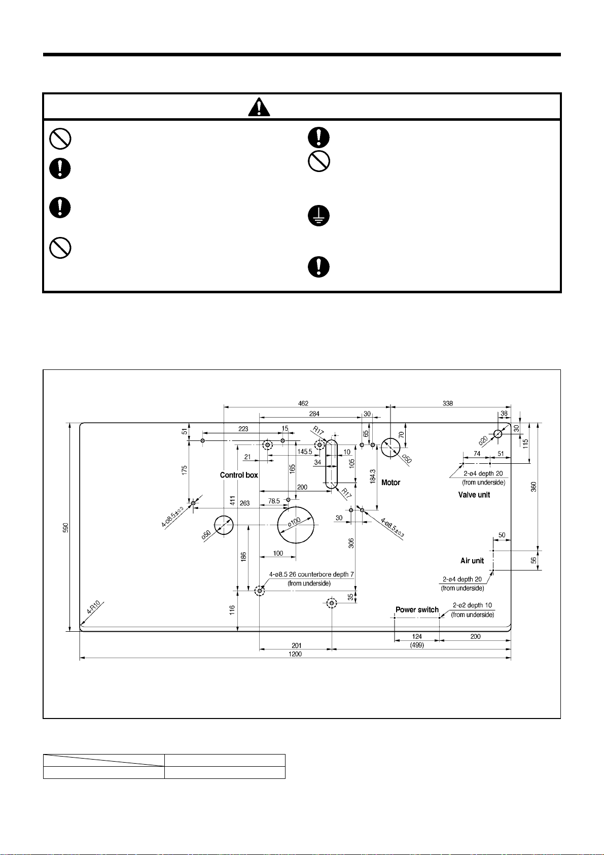
3-1. Table processing diagram
The top of the table should be 50 mm in thickness and should be strong enough to hold the weight and withstand the
vibration of the sewing machine. Drill holes in the table as shown in the diagram below.
* There is the special table indicated below.
Model code
Table/legs assembly 127-981-04902
0800Q
3. INSTALLATION
RH-981A
6
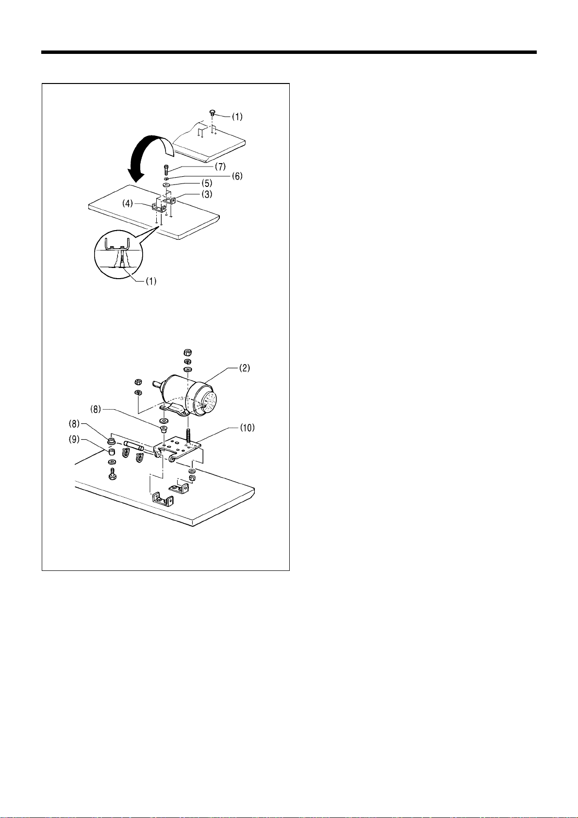
3-2. Installing the motor
1. Insert the four nuts (1) into the work table.
2. Turn the work table upside down to make it easier to
install the motor (2).
3. Align the holder plate (3) and the motor plate (4)
with the nuts (1), and t hen install them with the four
washers (5), the four spring washers (6) and the
four bolts (7).
4. Place the eight accessory cushions (7) and the four
accessory cushion collars (8) onto the motor base
plate (9), and then install the motor as shown in the
illustration.
Note: The vibration of the motor may cause the bolts
to come loose. Make sure that the bolts are
securely tightened.
3125Q
3124Q
3. INSTALLATION
RH-981A
7
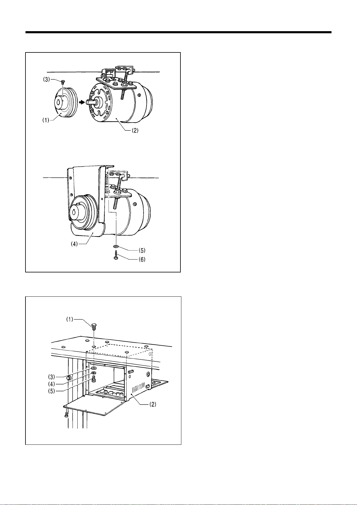
3-3. Installing the motor pulley
1. Place the motor pulley (1) onto the shaft of the
motor (2) so that the key grooves are alig ned, and
then tighten the set screws (3) so that the center of
the V groove in the motor pulley (1) is aligned as
closely as possible with the center of the belt hole in
the power table.
2. Install the m otor rear cover support (4) with the two
flat washers (5) and the two screws (6).
Note: Check that the motor rear cover support (4)
does not touch the motor pulley (1) or the
edge of the motor.
3-4. Installing the control box
1. Insert the four nuts (1) into the work table.
2. Open the front and rear covers of the control box
(2).
3. Align the control box (2) with the nuts (1), and then
install it with the four flat washers (3), spring
washers (4) and bolts (5).
Note: Be careful not to drop any small parts such
as washers onto the circuit board when
installing the bolts.
3126Q
3127Q
3128Q

3. INSTALLATION
RH-981A
8
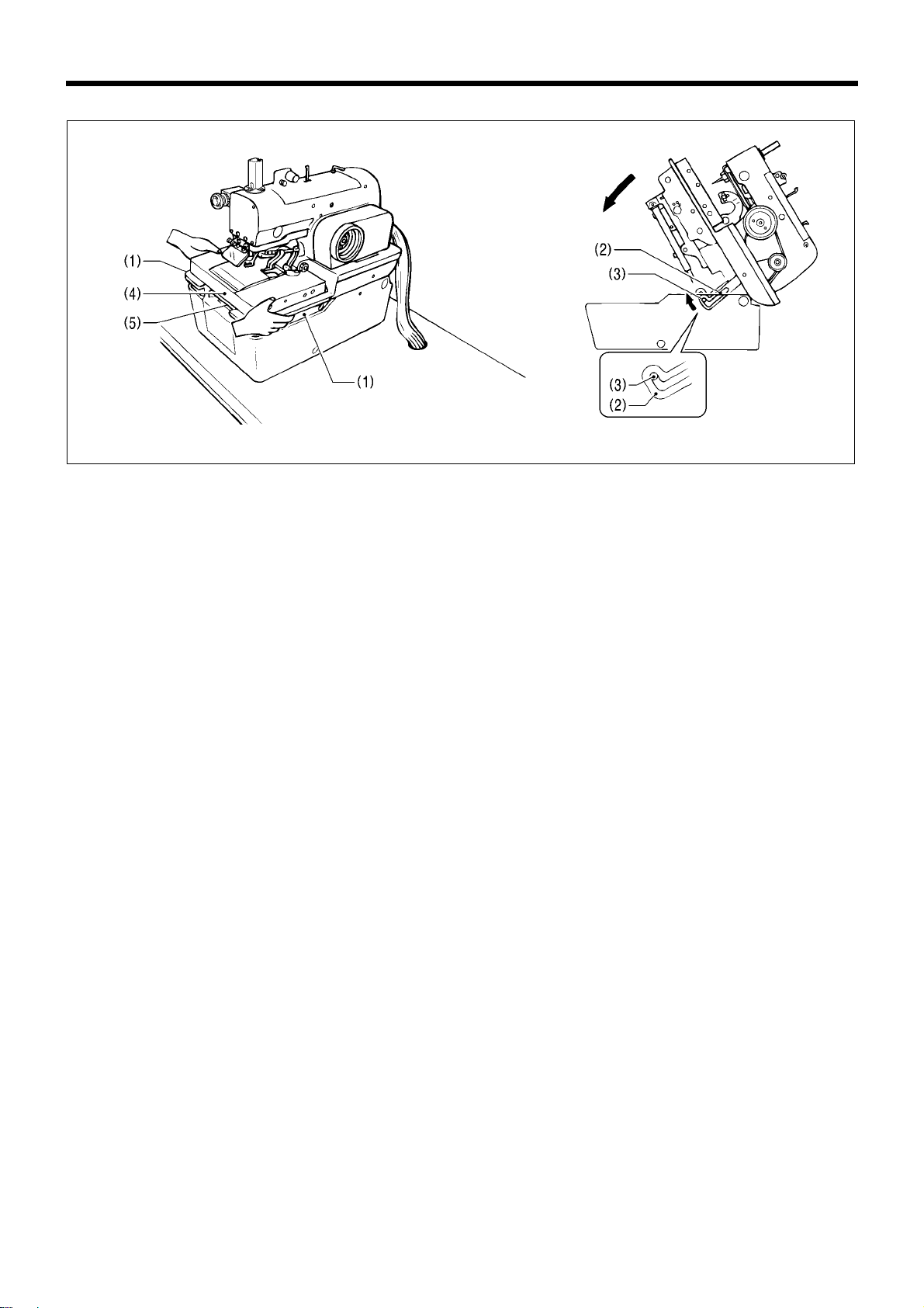
3-5. Installing the machine head
1. Insert the accessory bed base cushions A (1) into the bed base, and then plac e the machine head on top of the
work table.
Note: When placing the machine head on top of the work table, have two or more people there to hold the
handles and rear of the head as indicated in the illustration.
2. Open the front cover (2), and then use the bolt (3), washer (4), rubber s heet (5), bed stand cushion A (1) , large
washer (6) and nut (7) to attach the front right corner of the bed base to the work table.
3. Attach the bed base to the work table in two places inside the base in the same way as in step 2. above.
4. Remove the bolt (8) and the washer.
Note: The bolt (8) and washer should be kept, as they will be needed again if the machine head is moved.
5. Raise the machine head, and then attach the front left corner of the bed base to the work table in the same way as
in the steps above.
Note: Make sure that steps 2. to 4. above have been completed before raising the machine head.
6. Install the bed base cover (9) to the rear of the bed (10) with the four screws (11).
Note: Be careful not to injure yourself on the spring hinge.
2980Q
2981Q
2982Q
3. INSTALLATION
RH-981A
9
Raising the machine head
1. While holding the handles of the machine head (1) with both hands, gently raise the machine head.
Note: Be sure to turn the power supply off before raising the machine head.
2. If you wish to keep the machine head in the raised position, i nsert the head support lever (2) securely into the
hinge lever support shaft (3).
Note: Always check that the head support lever (2) and the hinge lever support shaft (3) are meshed.
Lowering the machine head
Pull the machine head down toward you gently, remove the head support lever (2) from the hinge lever support shaft
(3), and then gently lower the machine head.
Note: Do not hold the mac hine head by the feed bracket (4) or X feed shaft A (5) when it is bein g raised and
lowered.
2983Q
When machine
head is lowered
When machine head is raised
2984Q
3. INSTALLATION
RH-981A
10
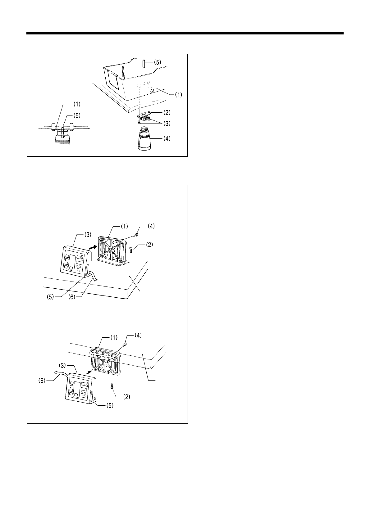
3-6. Installing the oil container
1. Install the oil draining cap suppor t (2) to th e base of
the bed base (1) with the two screws (3).
2. Sc rew the oil container (4) into the oil draining cap
support (2).
3. Push the oil draining spring pin (5) into the bed base
(1) until the pin is flush with the surface of the base.
4. Lower the machine head. (Refer to "Lowering the
machine head" on previous page.)
3-7. Installing the operation panel
The operation panel ca n be installed to either the top
or bottom of the work table.
1. Install the rear frame (1) to the work table (top or
bottom) with the four wood screws (2).
2. Install the front frame assembly (3) to the rear
frame (1) with the four screws (4).
* The vertical orientation of the front frame
assembly (3) is the same whether it is installed to
the top or the bottom of the work table.
* Pull the harnesses such as the ground harness
out of the way so that t he operation panel side
cover (5) can be opened and closed.
3. Insert the connector cord (6) into the control box
through the hole at the side of the box.
2985Q
2986Q
2987Q
Top of work table
Bottom of work table
Table
2988Q
Table
3. INSTALLATION
RH-981A
11
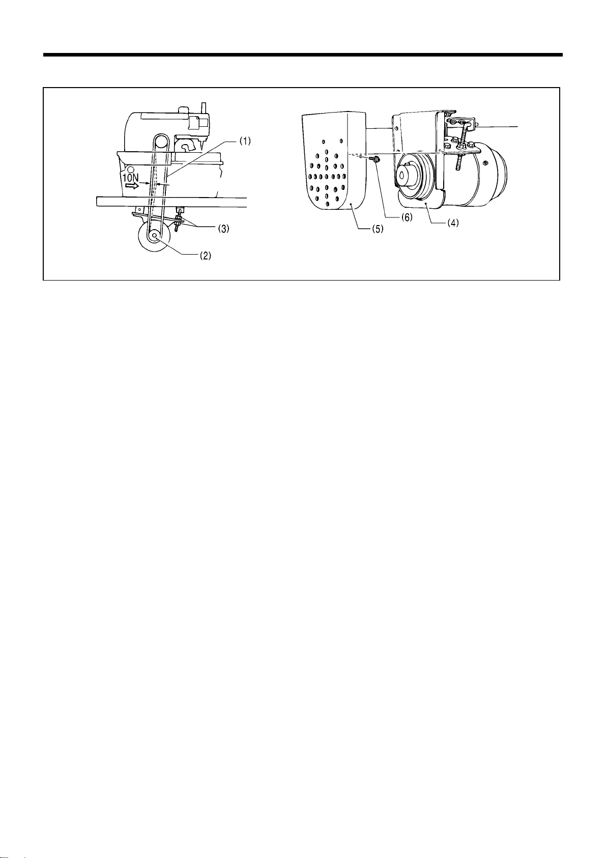
3-8. Tightening the V-belt
1. Open the rear cover.
2. Pass the V-belt (1) through the base of the bed base and through the hole in the work table.
3. Place the V-belt (1) onto the motor pulley (2).
4. Check that there is approximately 10 mm of deflection in the V-belt (1) when it is pushed in the middle with a load
of 10 N.
If the tightness needs adjusting, loosen the t wo nuts (3) and move the m otor up or down. After adjusting, t ighten
the nuts (3).
Note: Check that the motor rear cover support (4) does not touch the motor pulley (1) or the edge of the motor.
5. Install the motor cover (5) with the three screws (6).
Note: After a long period of use, the V-belt will become run in and will loosen around the motor pulley. When
this happens, turn off the power and adjust by the procedure given in step 4. above.
2990Q
2991Q
Approx.10 mm
3. INSTALLATION
RH-981A
12
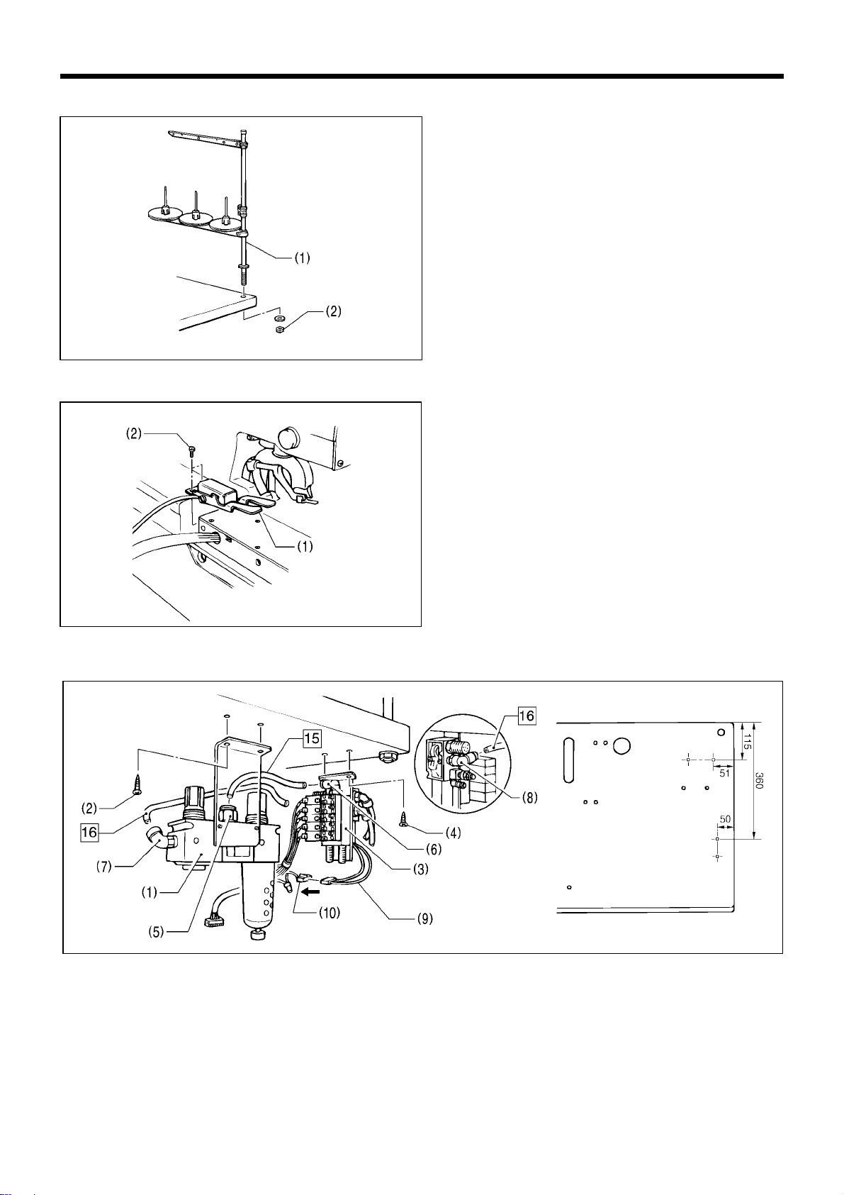
3-9. Installing the spool stand
1. To assemble the spool stand (1), follow the
instructions in the m anual that c ame with the spool
stand (1).
2. Secure the spoo l stand (1) to the rear right corner
of the work table with the washer and nut (2).
3-10. Installing the hand switch
Install the hand switch (1) with the two screws (2).
3-11. Installing the air unit and the valve unit
1. Install the air unit (1) to the underside of the work table with the two screws (2).
2. Install the valve unit (3) with the two screws (4).
3. Connect air tube No. 15 to the intermediate joint (5) of the air un it (1) and to the j o int (6) of the va lv e un it ( 3), and
connect air tube No. 16 to joints (7) and (8).
Connecting the valve cables
Insert the cable (9) which is coming out of the valve unit to the 2-pin connector (10) of the valve cable assembly.
2989Q
2992Q
Installation position
Air unit
Valve unit
2387Q
3129Q
3. INSTALLATION
RH-981A
13
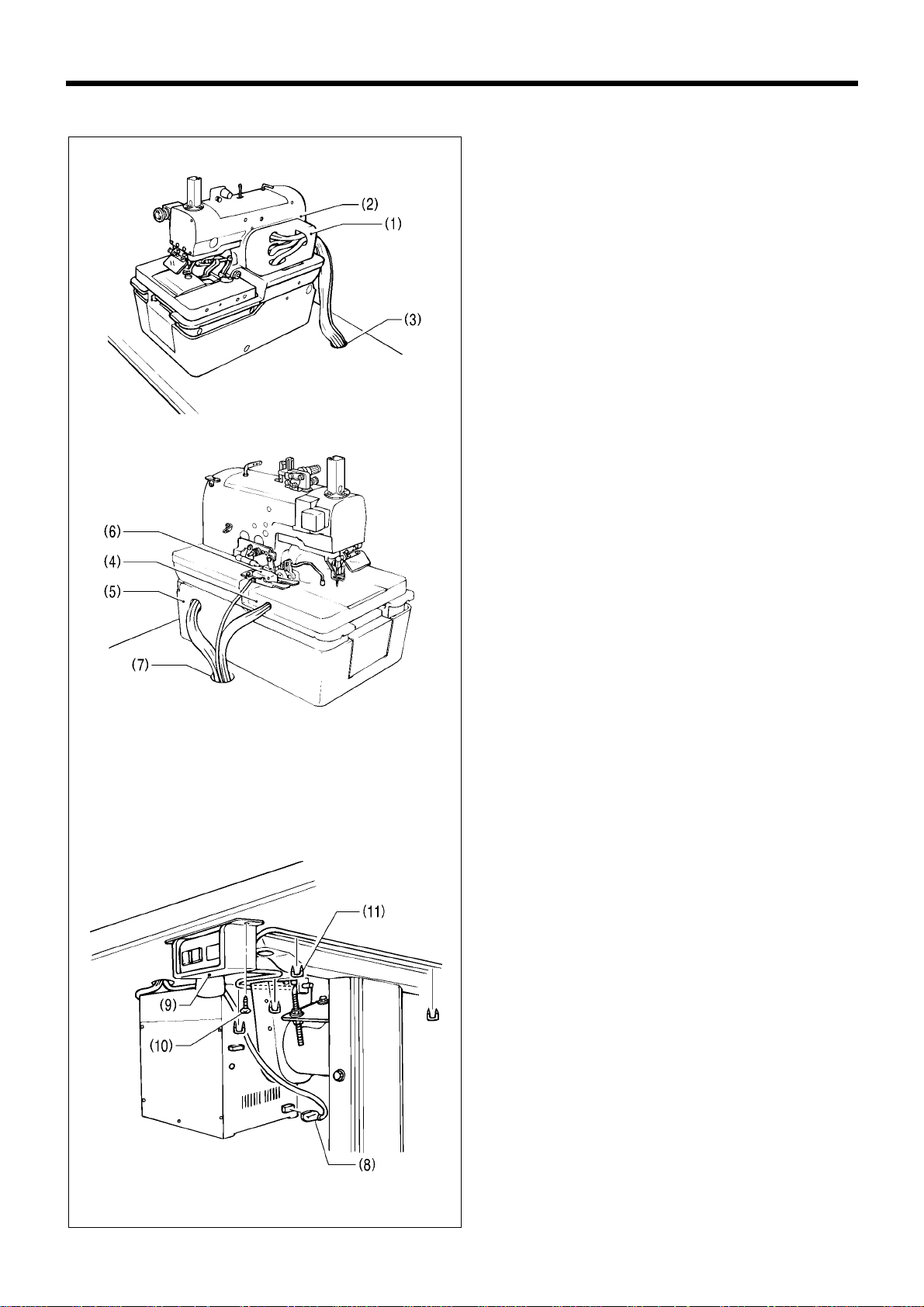
3-12. Connecting the wiring
1. Pass the cable and air tube which are coming out of
the belt cover (1) and the machine head ( 2) thro ugh
the cable hole (3) in the work table.
2. Pass the cables and air tube which are com ing out
of the feed bracket (4) and the lef t side of the bed
base (5) and the cable for the hand switch (6)
through the cable hole (7) in the work table.
Note: Leave enough looseness in the cables so
that they will not be pulled when the
machine head is tilted back.
Adjust the looseness after all connections to
the control box are complete.
3. Connect the hand switch connector (8) to the control
box connector.
4. Install th e power switch (9) to the underside of the
work table with the two screws (10).
5. Secure the cables using staples (11) (in four
locations).
2994Q
3130Q
3131Q
3. INSTALLATION
RH-981A
14
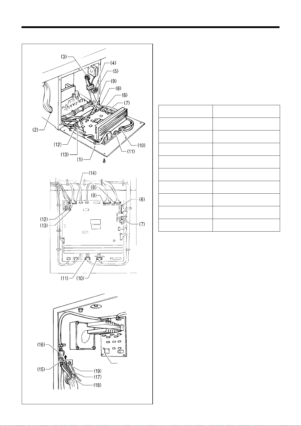
3-12-1. Connections inside the control box
1. Open the rear cover (1) of the control box.
2. Pass the cables through the holes (2) and (3) in th e
side of the control box.
3. Loosen the screw (5), and then connect the three
ground cables (4) that are coming f rom the m ac hine
head.
4. Securely insert each of the connectors (6) - (14) as
indicated below.
Machine head
connectors
(Connection indications)
* This is indicated on the P.C. board.
Connector (6)
(12-pin with [1] mark)
P1 (ORG)
Connector (7)
(5-pin with [2] mark)
P2 (SYNCHRO)
Connector (8)
(9-pin with [3] mark)
P3 (HEAD)
Connector (9)
(12-pin with [4] mark)
P4 (AIR)
Connector (10)
(5-pin with [6] mark)
P6 (YPM) (BLUE)
Connector (11)
(5-pin with [7] mark)
P7 (XPM)
Connector (12)
(16-pin with [8] mark)
P8 (EXINA)
Connector (13)
(18-pin with [9] mark)
P9 (EXINB)
Connector (14)
(10-pin)
P18 (PANEL)
5. Insert the connector (15) (6-pin with [1][R] mark) to
the connector (16).
6. Loosen the middle screw (19) and then install the
ground cable (17) and the thr ee ground cables (18)
from the operation panel.
7. Secure the cables with the c abl e clamp as shown in
the illustration.
Note: W hen secur ing the cables, do not l et any of
the cables touch the components on the
circuit board or the heat s ink. Furthermore,
adjust the lengths of the cables from outside
the control box so that there is no looseness
in the cables inside the control box.
2997Q
2998Q
2999Q
PMD circuit
Board
3. INSTALLATION
RH-981A
15
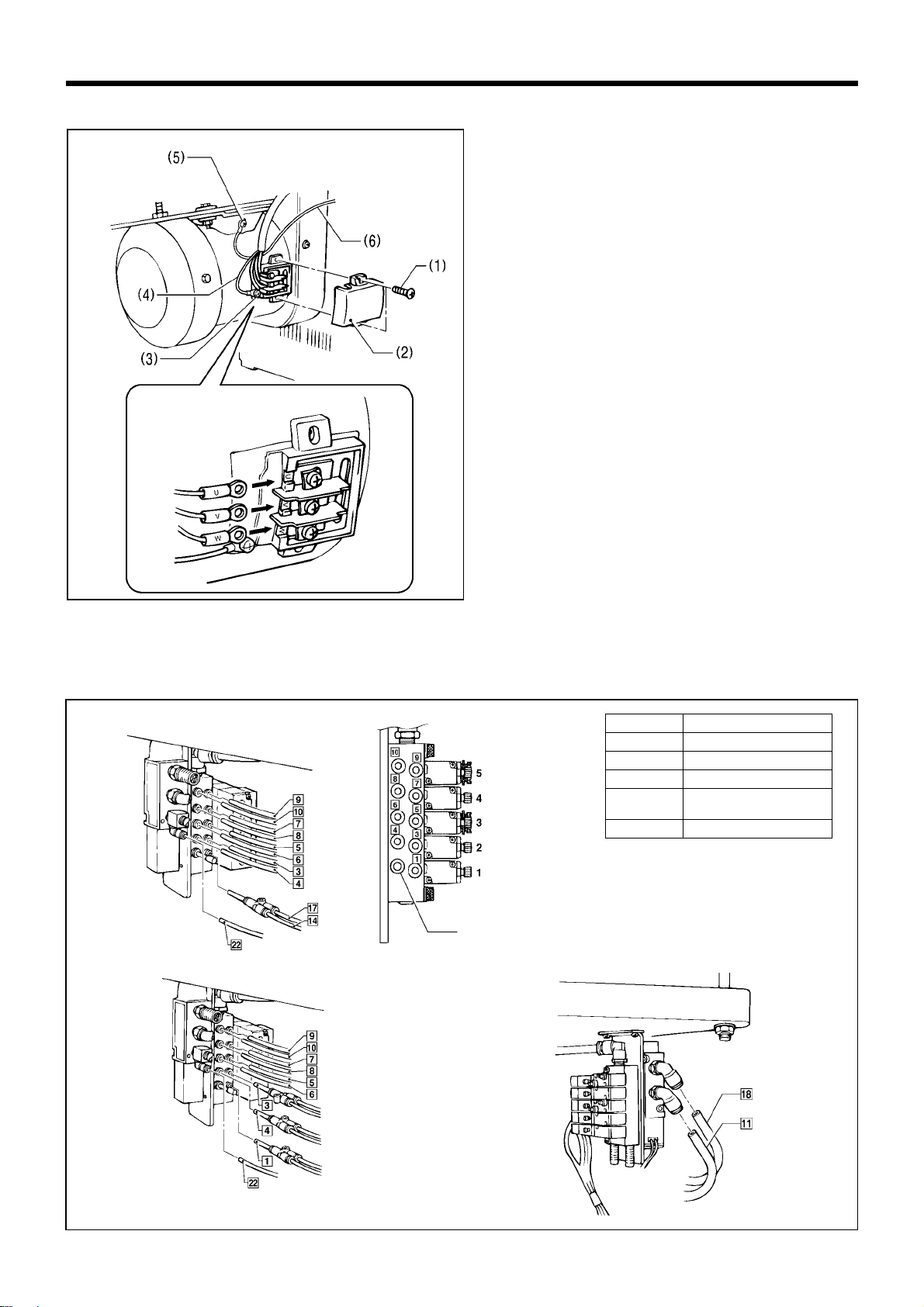
3-12-2. Connecting the motor cables
1. Remove the screws (1), and then open the terminal
block cover (2) of the motor.
2. Loosen the screw (3) and connect the ground cable
(4) for the motor.
3. Loosen the screw (5) and connect the ground cable
(6) from the control box.
4. Connect the cables so that the cable m arks (U, V,
W) match the symbols on the screw terminals.
5. Close the cover (2).
Note: Be careful not to clamp the cables when
closing the cover.
3-12-3. Connecting the air tubes
Connect the air tubes to the joints of the solenoid valve assembly, using the illustration below as a reference.
Numbers are marked on each of the air hoses which come out of the sewing machine.
3000Q
0827Q
Label No.
Solenoid valve
5
Upper thread trimming
4
Upper thread tightening
3
Lower thread tr
i
mm
i
ng *1
2
Cloth spreading
(Auxiliary clamp arm *2)
1
Wor k clamp
*1 If the lower thread trimmer is not
installed, solenoid valve [3] is not
used.
*2 The auxiliary clamp arm can only be
used for machines with -02
specification.
0826Q
Plug 4
< -00, -01 >
0829Q
0828Q
< -02 >
3. INSTALLATION
RH-981A
16
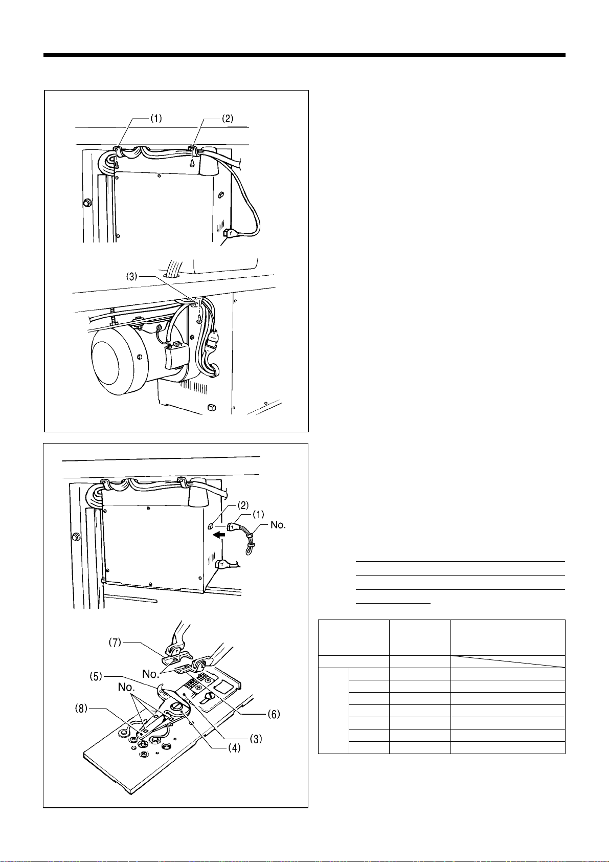
3-12-4. Securing the cables
Note: Leav e enough loos eness in t he cables s o that
they will not be pulled when the machine head
is tilted back.
1. Pass the cable through the cable holder (1), and
then secure the cable holder (1) to the und erside of
the work table with the screw.
2. Pass the air tube and the hand switch cable through
the cable holder (2), and then secure the cable
holder (2) to the underside of the work table with the
screw.
3. Place the machine head cable together with the
valve cable assembly and motor cable, pas s them
all through the cable holder (3), and th en sec ur e the
cable holder (3) to the underside of the work table
with the screw.
Insert the specific ation harnes s (1) into the control box
connector (2).
Note: Check that the label number on the
specification harness (1) matches the movable
knife (R) (3), movable knife (L) (4), thread
handler (5), work clamp (R) (6), work clamp (L)
(7) and movable knife driving cam (8) numbers
before inserting the spec ification harness (1).
(If a connector with an incorrect label n umber
is connected, it may cause problem s such as
damage to the sewing machine or thread
trimming errors.)
Specification
Label No.
of harness
Right/left work clamp No.
Right/left mo v abl e knife No.
Thread handler No.
-00, -01 0
L1 1 1
L2 2 2
L3 3 3
L4 4 4
L5 5 5
L6 6 6
-02
L7 7 7
* There is 10 mm of difference in the knife installat ion
positions between L1 - L4 and L5 - L7.
3132Q
3002Q
3004Q
3003Q
3. INSTALLATION
RH-981A
17
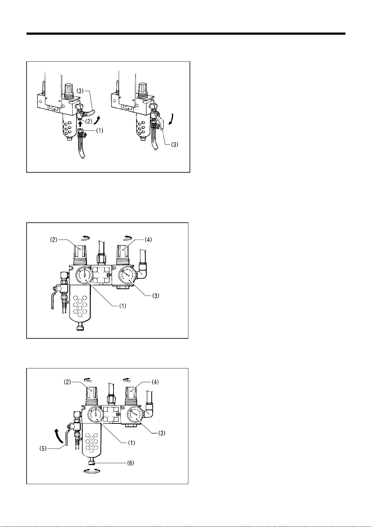
3-13. Installing the air tubes
Connect the air tube from the compressor to the air unit underneath the work table.
1. T urn the nut (1) at the end of the air tube, and the n
connect the tube to the valve (2).
2. Open the air cock (3) on the compressor.
Check that there is no air leaking from the valve
connection.
3. Open the cock (3) by turning it in the direction of the
arrow.
The meter needle will move clockwise.
4. Adjust the air pressure.
3-13-1. Adjusting the air pressure
Set the air pressure for the k nife pres sur e adj ustment regulator (3) to the lowest pressur e at which the knife can still
cut the material. Set the standard air pressure for the main regulator (1) to 0.5 MPa.
To increase the air pressure
1. Gently lif t the k nob (2 ) of the m ain r egulator (1) and
turn it in the direction of the arrow in the illustration.
The pressure will increase when the knob (2) is
turned clockwise.
2. Gently lift the knob (4) of the knife pressure
adjustment regulator (3) and turn it in the dir ection
of the arrow in the illustration.
The pressure will increase when the knob (4) is
turned clockwise.
* The pressure for the knife pressure adjustment
regulator (3) is adjusted to 0.3 MPa. Be careful not
to increase this pressure needlessly, otherwise
poor cutting performanc e or damage to the knife
may result.
To decrease the air pressure
1. Close the cock (5). (The needle will remain at the
high pressure position.)
2. Turn the knob screw (6) in the d irec tion of the ar row
in the illustration to loosen it. Make sure that you
turn it in the correct direction.
The air will escape from the reservoir and the needle
will drop.
3. Tighten the knob screw (6).
4. To reduce the air pressure, gently lift knob (2) or
knob (4) and turn it counterclockwise.
5. Open the cock (5). Air will enter the reservoir and
the needle will move
3006Q
(0.3MPa)
(0.5MPa)
3007Q
(0.5Mpa)
(0.3Mpa)
To close
To tighten
To loosen
3005Q
Closed
Open
3. INSTALLATION
RH-981A
18
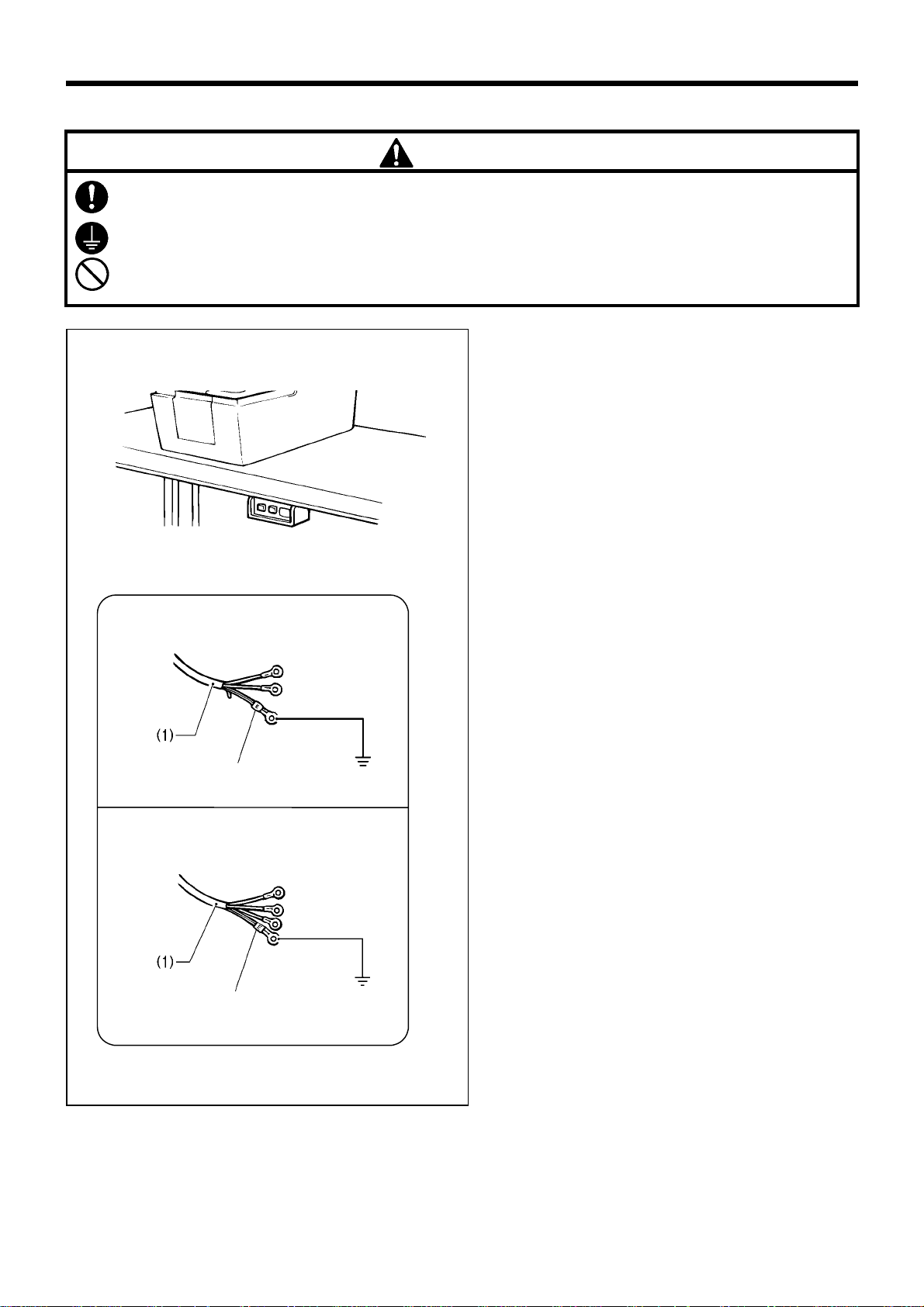
3-14. Connecting the power cord
CAUTION
Contact your Brother dealer or a qualified electrician for any electrical work that may need to be done.
Be sure to connect the ground. If the gr ound connection is not secure, you run a high risk of receiving a
serious electric shock, and problems with correct operation may also occur.
Do not connect the power cord until installation is complete, otherwise the machine may operate if the start
switch is pressed by mistake, which could result in injury.
1. Attach an appropriate plug to the power cord (1).
(The green and yellow wire is the ground wire.)
2. Insert the plug into properly-grounded AC power
supply.
Note: Do not use extension cords, otherwise
machine operation problems may result.
0838Q
Three phase
Green and yellow wire
(ground wire)
3134Q
Single phase
Green and yellow wire
(ground wire)
3133Q
3. INSTALLATION
RH-981A
19
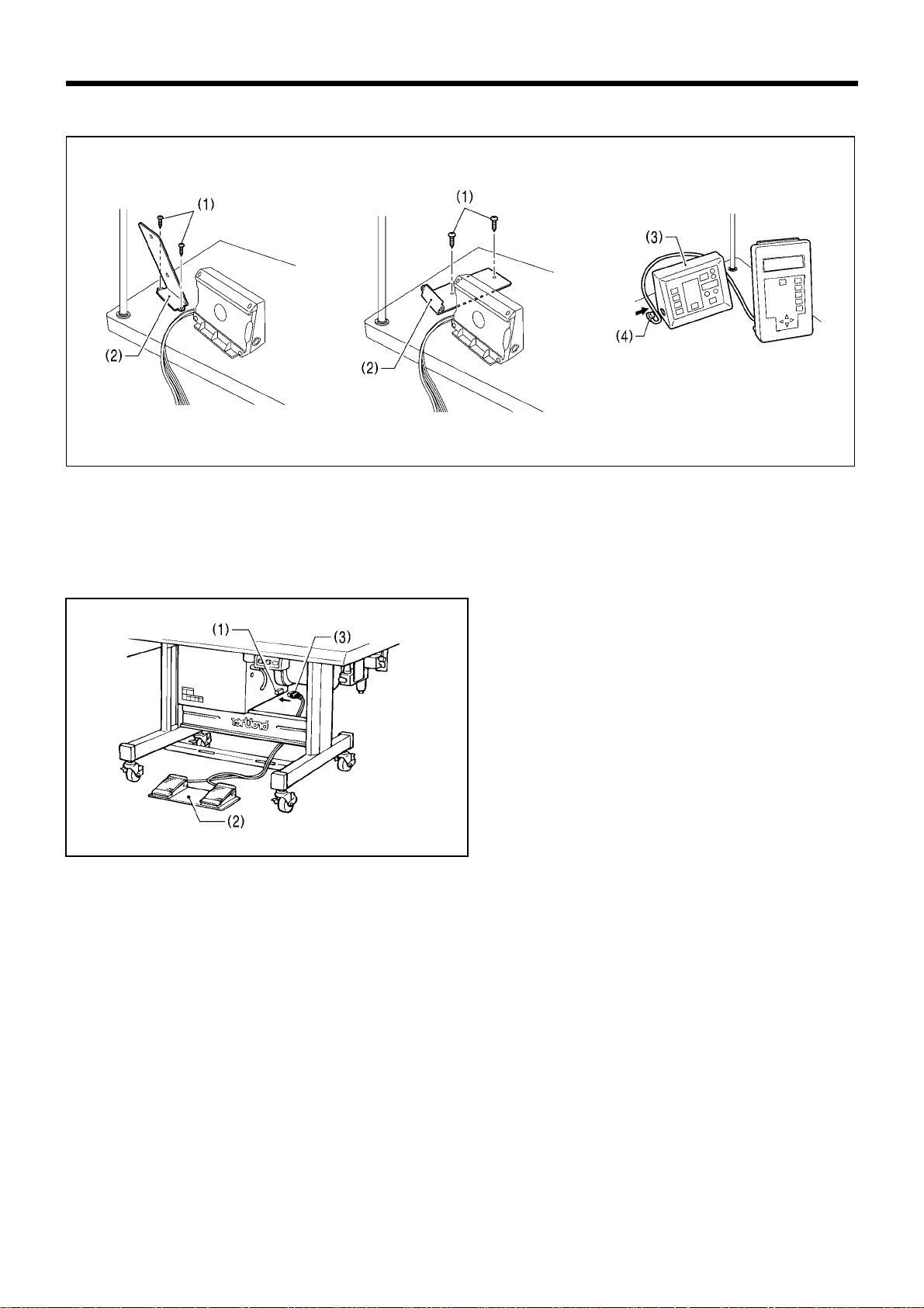
3-15. Installing the programmer (sold separately)
1. Install the programmer support (2) to the work table with the two screws (1).
2. Insert the programmer connector (4) securely into the left side of the operation panel (3).
3-16. Installing the foot switch (option)
Insert the connector (3) of the foot switch (2) into the
control box connector (1).
[Vertical]
3010Q 3011Q
3012Q
[Flat]
3135Q
3. INSTALLATION
RH-981A
20
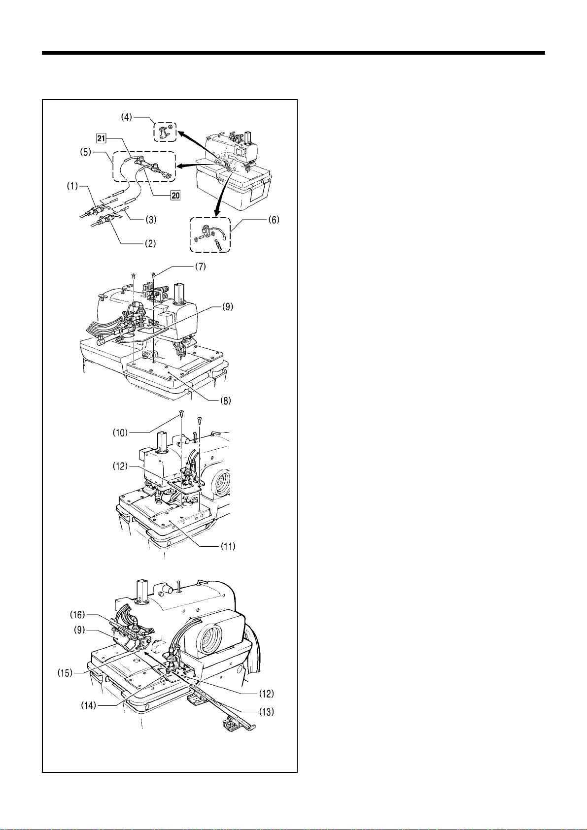
3-17. Installing the indexer (option)
3-17-1. Installing the indexer main unit
1. After disconnecting air tubes [20] and [21], insert the
two plugs (3) into joints (1) and (2). In addition,
remove parts (4), (5) and (6) indicated in the
illustration.
2. Remove the screws (7) from feed bracket cover (L)
(8), and then install feed base (L) (9).
3. Remove the screws (10) from feed bracket cover
(R) (11), and then install feed base (R) (12).
4. Pas s the cloth feed bar (13) bet ween the rollers of
feed bar guide (R) (14) and feed bar guide (L) (15),
and place it on top of feed base (L) (9) and feed
base (R) (12).
* Push down the chuck pin (16) and c heck that it
goes smoothly into all of the holes in the cloth
feed bar (13).
If it does not go in smoothly, re-adjust the
installation positions of feed base (L) (9) and feed
base (R) (12).
3015Q
3016Q
3017Q
3018Q
Loading...