


SERVICE MANUAL
MODEL: PT-2300/2310/2450
SERVICE MANUAL
MODEL: PT-2300/2310/2450
PREFACE
This publication is a service manual covering the specifications, theory of operation, disassembly/reassembly procedure, and troubleshooting and error message of the Brother PT2300/2310/2450. It is intended for service personnel and other concerned persons to accurately and quickly provide after-sale service for our PT-2300/2310/2450.
To perform appropriate maintenance so that the machine is always in best condition for the customer, the service personnel must adequately understand and apply this manual.
This manual is made up of four chapters and appendices.
CHAPTER I |
SPECIFICATIONS |
CHAPTER II |
MECHANISMS |
CHAPTER III |
ELECTRONICS |
CHAPTER IV |
TROUBLESHOOTING AND ERROR MESSAGE |
APPENDICES |
1. SOFTWARE TO WRITE THE SERIAL NUMBER |
|
2. CIRCUIT DIAGRAMS |
© Copyright Brother 2001
All rights reserved.
No part of this publication may be reproduced in any form or by any means without permission in writing from the publisher.
Specifications are subject to change without notice.
CHAPTER I
SPECIFICATIONS
CONTENTS
CHAPTER I SPECIFICATIONS......................................................................... |
I-1 |
||
1.1 |
MECHANICAL SPECIFICATIONS ........................................................................ |
I-1 |
|
|
1.1.1 |
External Appearance ...................................................................................... |
I-1 |
|
1.1.2 |
Keyboard........................................................................................................ |
I-2 |
|
1.1.3 |
Display ........................................................................................................... |
I-2 |
|
1.1.4 |
Printing Mechanism........................................................................................ |
I-2 |
|
1.1.5 |
Tape Cassette ................................................................................................ |
I-3 |
|
1.1.6 |
Tape Cutter .................................................................................................... |
I-3 |
1.2 |
ELECTRONICS SPECIFICATIONS ...................................................................... |
I-9 |
|
|
1.2.1 |
Character Generator....................................................................................... |
I-9 |
|
1.2.2 |
Power Supply ................................................................................................. |
I-9 |
1.3 |
KEY COMMANDS FOR SPECIAL FUNCTIONS ................................................... |
I-9 |
|
|
1.3.1 |
Initializing ....................................................................................................... |
I-9 |
|
1.3.2 |
Demonstration Print........................................................................................ |
I-9 |
i
CHAPTER I SPECIFICATIONS
1.1MECHANICAL SPECIFICATIONS
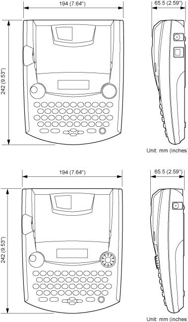
1.1.1External Appearance
(PT-2300/2310)
(PT-2450)
Fig. 1.1-1 PT-2300/2310/2450
(1)Dimensions (W x D x H) 194 x 242 x 65.5 mm (7.64" x 9.53" x 2.59")
(2)Weight
Machine proper |
Approx. 900 g |
In package |
Approx. 1.6 kg (PT-2300/2450) |
|
Approx. 2.9 kg (PT-2310/2450cc) |
|
(including batteries, a tape cassette, and user's manual) |
I-1

1.1.2Keyboard
(1) |
Entry system |
Rubber key pad |
(2) |
Number of alphanumeric and symbol keys |
39 |
(3) |
Number of function keys |
12 (including “On/Off ( ) ” key) |
(4) |
Key arrangement |
See Fig. 1.1-2. |
(5) |
Navigation dial (PT-2450) |
Rotary switch : 20 positions / cycle |
|
|
Set key : 1 |
1.1.3Display
(1) |
Display type |
Liquid crystal display (LCD) |
(2) |
Display composition |
16 x 59 dots |
(3) |
Number of indicators |
20 (See Fig. 1.1-2.) |
(4) |
Dot size |
0.65 mm(25.6mils) wide by 0.65 mm(25.6mils) high |
(5) |
Field-of-view angle adjustment |
Fixed by a resistor |
1.1.4Printing Mechanism
(1) |
Print method |
Thermal transfer onto plastic tapes (laminate tape and |
|||
|
|
non-laminated tape) or special tapes (instant lettering tape, |
|||
|
|
non-laminated thermal film tape, iron-on transfer tape, and |
|||
|
|
porous-stamp tape) |
|||
|
|
(Fixed print head and tape feeding mechanism) |
|||
(2) |
Print speed |
10 mm/second (Typical) |
|||
(3) |
Print head |
|
|
|
|
|
Type |
Thermal print head |
|||
|
Heat generator |
Consists of 112 heating elements vertically aligned |
|||
|
|
(PT-2450 : 128 heating elements) |
|||
|
Size of heating element |
0.195 mm (7.7 mils) wide by 0.141 mm (5.6 mils) high |
|||
(4) |
Character size |
|
|
|
|
|
|
|
|
|
|
|
|
Character size |
|
Height x Width (dots) |
|
|
|
|
|
|
|
|
|
Size 6 |
|
1.55 mm x 1.13 mm (11 x 8) |
|
|
|
|
|
|
|
|
|
Size 9 |
|
1.97 mm x 1.41 mm (14 x 10) |
|
|
|
|
|
|
|
|
|
Size 12 |
|
2.82 mm x 2.12 mm (20 x 15) |
|
|
|
|
|
|
|
|
|
Size 18 |
|
4.51 mm x 3.38 mm (32 x 24) |
|
|
|
|
|
|
|
|
|
Size 24 |
|
5.92 mm x 4.37 mm (42 x 31) |
|
|
|
|
|
|
|
|
|
Big <12 mm> |
|
7.61 mm x 5.64 mm (54x 40) |
|
|
|
|
|
|
|
|
|
Size 36 |
|
9.02 mm x 6.77 mm (64 x 48) |
|
|
|
|
|
|
|
|
|
Size 42 (PT-2300/2310) |
|
10.72 mm x 8.04 mm (76 x 57) |
|
|
|
|
|
|
|
|
|
Size 48 (PT-2450) |
|
11.84 mm x 8.74 mm (84 x 62) |
|
|
|
|
|
|
|
|
|
Big <18 mm> (PT-2300/2310) |
13.54 mm x 10.30 mm (96 x 73) |
|
|
|
|
|
|
|
|
|
|
Big <24 mm> (PT-2450) |
16.07 mm x 11.99 mm (114 x 85) |
|
|
|
|
|
|
|
|
*The height and width of the printed character are different depending on characters. The values in the above list refer to the values of ‘H’ of HELSINKI.
*The character size indicates the point size.
I-2
1.1.5Tape Cassette
(1) |
Cassette |
Cartridge type |
|
(2) Types of tape cassettes |
|
|
|
|
• Laminated tape cassette |
Laminate tape, ink ribbon, and adhesive base tape |
|
|
• Non-laminated tape cassette |
Non-laminate tape and ink ribbon |
|
|
• Instant lettering tape cassette |
Instant lettering tape and ink ribbon |
|
|
• Non-laminated thermal film |
Non-laminated thermal film tape |
|
|
tape cassette |
|
|
|
• Iron-on transfer tape cassette |
Iron-on transfer tape and ink ribbon |
|
|
• Stamp tape cassette |
Porous-stamp tape and base paper |
|
|
• Cloth tape cassette |
Cloth tape and ink ribbon |
|
(3) |
Tape size |
|
|
|
|
|
|
|
|
Width |
Length |
|
|
|
|
|
Laminate tape |
6, 9, 12, 18, 24 |
8 m |
|
|
mm |
(5 m for the fluorescent coating tape) |
|
|
|
|
|
|
|
|
|
Non-laminate tape |
6, 9, 12, 18, 24 |
8 m |
|
|
mm |
|
|
|
|
|
|
Instant lettering tape |
18 mm |
8 m |
|
|
|
|
|
Non-laminate thermal film |
12, 18 mm |
8 m |
|
tape |
|
|
|
|
|
|
|
Iron-on transfer tape |
18 mm |
6 m |
|
|
|
|
|
Porous-stamp tape |
18, 24 mm |
3 m |
|
|
|
|
|
Cloth tape |
12 mm |
4 m |
|
|
|
|
(4)Tape cassette packed with the machine
Laminated tape cassette containing a 12-mm-wide black ink ribbon, laminate tape, and adhesive base tape
1.1.6Tape Cutter
(1) |
Tape cutting |
Automatic cutter (scissors type) |
(2) |
Cutter unit |
Not user-replaceable |
I-3
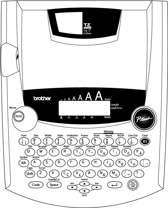
PT-2300/2310 U.S.A.
Fig. 1.1-2 Key Arrangement (1)
I-4
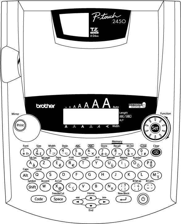
PT-2450 BELGIUM
Fig. 1.1-2 Key Arrangement (2)
I-5
PT-2450 FRENCH
Fig. 1.1-2 Key Arrangement (3)
I-6

PT-2450 GERMAN
Fig. 1.1-2 Key Arrangement (4)
I-7

PT-2450 U.K.
Fig. 1.1-2 Key Arrangement (5)
I-8
1.2ELECTRONICS SPECIFICATIONS
1.2.1Character Generator
(1) |
Internal characters |
U.S.A. (PT-2300/2310) |
179 characters |
|
|
|
U.K./ FRA/ BEL (PT-2450) |
199 characters |
|
|
|
GER (PT-2450) |
|
216 characters |
(2) |
Internal font |
HELSINKI, BRUSSELS, FLORIDA, US (PT-2300/2310) |
||
|
|
HELSINKI, BRUSSELS, FLORIDA, BELGIUM, |
||
|
|
LOS ANGELS, SAN DIEGO, ISTANBUL, US (PT-2450) |
||
(3) |
Internal memory |
Text buffer |
99 characters (PT-2300/2310) |
|
|
|
|
255 characters (PT-2450) |
|
|
|
File memory |
300 characters (PT-2300/2310) |
|
|
|
|
2500 characters (PT-2450) |
|
1.2.2 Power Supply |
|
|
|
|
(1) |
Automatic power off |
Yes |
|
|
|
|
Normal mode : 5 min. ± 30 sec. |
|
|
|
|
IF mode : 30 min. ± 30 sec. (PT-2300/2310) |
||
1.3KEY COMMANDS FOR SPECIAL FUNCTIONS
1.3.1Initializing
Powering on the machine with both the Code and R keys held down will initialize the machine.
1.3.2Demonstration Print
Pressing the D key with the Code key held down will start demonstration print. (This key command takes effect only when no data is entered.)
I-9
CHAPTER II
MECHANISMS
CONTENTS
CHAPTER II MECHANISMS.............................................................................. |
II-1 |
||
2.1 |
THEORY OF OPERATION ................................................................................... |
II-1 |
|
|
2.1.1 |
Print Mechanism ............................................................................................ |
II-1 |
|
2.1.2 Roller Holder ASSY Setting & Retracting Mechanism..................................... |
II-3 |
|
|
2.1.3 Tape & Ribbon Feed Mechanism.................................................................... |
II-4 |
|
|
2.1.4 Automatic Tape Cutter Mechanism................................................................. |
II-6 |
|
|
2.1.5 Roller Holder ASSY & Cassette Cover Interlocking Mechanism...................... |
II-7 |
|
2.2 |
DISASSEMBLY & REASSEMBLY......................................................................... |
II-8 |
|
|
2.2.1 |
Disassembly Procedure.................................................................................. |
II-8 |
|
[ 1 ] |
Removing the Battery Lid and Batteries....................................................... |
II-8 |
|
[ 2 ] |
Removing the Tape Cassette and Tape Separator Stick.............................. |
II-9 |
|
[ 3 ] |
Removing the Bottom Cover ....................................................................... |
II-10 |
|
[ 4 ] |
Removing the Cassette Cover, Chassis ASSY and Shield Plate.................. |
II-12 |
|
[ 5 ] |
Removing the Main PCB and Rubber Key Pad............................................ |
II-18 |
|
[ 6 ] |
Removing the Switch ASSY ........................................................................ |
II-20 |
|
[ 7 ] |
Removing the Blind Cover........................................................................... |
II-20 |
|
[ 8 ] |
Removing the Power Supply PCB ............................................................... |
II-21 |
|
[ 9 ] |
Removing the Battery Terminals ................................................................. |
II-22 |
|
2.2.2 |
Reassembly Procedure .................................................................................. |
II-23 |
|
[ 1 ] |
Installing the Battery Terminals ................................................................... |
II-23 |
|
[ 2 ] |
Installing the Power Supply PCB ................................................................. |
II-24 |
|
[ 3 ] |
Installing the Blind Cover............................................................................. |
II-26 |
|
[ 4 ] |
Installing the Switch ASSY .......................................................................... |
II-26 |
|
[ 5 ] |
Installing the Rubber Key Pad ..................................................................... |
II-27 |
|
[ 6 ] |
Installing the Main PCB ............................................................................... |
II-28 |
|
[ 7 ] |
Installing the Chassis ASSY and Shield Plate .............................................. |
II-29 |
|
[ 8 ] |
Installing the Bottom Cover ......................................................................... |
II-34 |
|
[ 9 ] |
Installing the Cassette Cover ....................................................................... |
II-36 |
i
[ 10 ] |
Installing the Tape Cassette and Tape Separator Stick................................ |
II-36 |
[ 11 ] |
Loading Batteries and Installing the Battery Lid ........................................... |
II-37 |
[ 12 ] |
Demonstration Print and Final Check .......................................................... |
II-38 |
ii

CHAPTER II MECHANISMS
2.1THEORY OF OPERATION
2.1.1Print Mechanism
(1)Structure of Thermal Head
This machine uses thermal transfer printing. The thermal print head has a heat generator consisting of 112 heating elements (PT-2450 : 128 heating elements ) which are vertically aligned as shown in Fig. 2.1-1.
Each heating element is 0.195 mm wide by 0.141 mm high.
Fig. 2.1-1 Heat Generator of Thermal Head
(2)Printing Process
When the cylindrical rubber platen is pressed against the thermal print head with the tape* and ink ribbon** sandwiched inbetween, the CPU applies electric power to the selected ones of those 112 heating elements. (PT-2450 : 128 heating elements)
*Laminate tape when using laminated tape cassettes.
Non-laminated tape when using non-laminated tape cassettes. Instant lettering tape when using instant lettering tape cassettes.
Non-laminated thermal film tape when using non-laminated thermal film tape cassettes. Iron-on transfer tape when using iron-on transfer tape cassettes.
Cloth tape when using cloth tape cassettes.
**When using non-laminated thermal film tape cassettes or stamp tape cassettes, no ink ribbon is sandwiched.
[For tape cassettes except non-laminated thermal film tape cassettes and stamp tape cassettes]
If the selected heating element(s) generates heat, the ink on the sandwiched ribbon will be melted and transferred to the tape, producing a dot(s) on the tape. The ink ribbon and the tape are advanced and then the next heating cycle is repeated, thus forming a character on the tape.
[For non-laminated thermal film tape cassettes]
If the selected heating element(s) generates heat, the thermal film tape develops itself to produce a dot on the tape. The tape is advanced and the next heating cycle is repeated, thus forming a character on the tape.
II-1
[For stamp tape cassettes]
If the selected heating element(s) generates heat, the porous-stamp tape will be melted so that a pore (pores) will be formed in the tape. The tape is advanced and the next heating cycle is repeated, thus forming a character of pores on the tape. The printed stamp tape can be used as the face of a stamp. When the stamp is pressed against the ink-pad, it will absorb ink through the pores.
For laminated tape cassettes, instant lettering tape cassettes, and iron-on transfer tape cassettes, the CPU processes the print data to generate a mirror image so that the printed character can be seen normally when viewed from the other side of the printed face of the tape.
(3)Character Formation
While the DC motor feeds the tape and ink ribbon (only the tape when using non-laminated thermal film tape cassettes or stamp tape cassettes) by 0.141 mm, the thermal head generates heat once. The feed amount is decided by sending each five pulses of the signal as one dot (0.141 mm) when the photo interrupter detects the encode gear assembled onto the motor shaft. The feed amount of 0.141 mm is smaller than the width (0.195 mm) of the heating elements so that the heat generated at one heating cycle will overlap with the next heating cycle. This forms a character having no gap between adjacent printed dots.
II-2

2.1.2Roller Holder ASSY Setting & Retracting Mechanism
This mechanism consists of the roller release lever, roller holder release rod, and roller holder ASSY.
The roller holder ASSY supports the platen and the tape feed sub roller so that they can move perpendicularly to the head ASSY and the tape feed roller, respectively, as well as rotating freely.
Loading a tape cassette and closing the cassette cover pushes down the roller release lever which moves the roller holder release rod to the left (when viewed from the front of the machine). This pivots the roller holder ASSY around the shaft provided on the chassis so as to press the roller holder ASSY against the head ASSY side.
The platen is pressed perpendicularly against the head ASSY with the tape and ink ribbon (only the tape when using non-laminated thermal film tape cassettes or stamp tape cassettes) sandwiched inbetween under a uniform load by the platen (upper and lower) spring.
At the same time, the platen gear becomes engaged with the platen idle gear.
Also, the tape feed sub roller is pressed perpendicularly against the tape feed roller built in the tape cassette with the tape (and base paper when using laminated tape cassettes or stamp tape cassettes) sandwiched inbetween under a uniform load by the roller holder upper spring and roller holder lower spring. At the same time, the sub roller gear becomes engaged with the tape idle gear.
If you open the cassette cover, the roller release lever pops up, which shifts the roller holder release rod so that the roller holder ASSY is retracted from the head ASSY, providing you with enough space to replace the tape cassette.
Head ASSY
Adhesive base tape
Platen idle gear
Tape feed roller
Tape feed sub roller
Platen roller
Roller holder ASSY
(Tape feed) platen gear
Platen roller
(Tape feed) sub roller gear
Laminate tape
Tape cassette
Ink ribbon
Chassis ASSY
Roller release lever
Shaft Roller holder release rod
Platen lower spring
Platen upper spring
(Top)
Tape feed sub roller
Fig. 2.1-2 Roller Holder ASSY Setting & Retracting Mechanism
II-3
2.1.3Tape & Ribbon Feed Mechanism
This mechanism consists of a DC motor, gear train, and roller holder ASSY.
(1)Tape Feeding
When you load a tape cassette and close the cassette cover, the tape feed roller inside the cassette and the tape feed sub roller in the roller holder ASSY sandwich the tape (the laminate tape and adhesive base tape when using laminated tape cassettes) inbetween, as described in Subsection 2.1.2.
As the DC motor rotates, the rotation is transmitted via the gear train to the tape idle gear (which rotates the tape feed sub roller gear) and the platen idle gear (which rotates the tape feed platen gear). Accordingly, the sandwiched tape and ink ribbon will be advanced. (When a laminated tape cassette is mounted, the sandwiched laminate tape and adhesive base tape and ink ribbon will be advanced together.)
The feeding amount of the platen is slighty less than that of the tape feed sub roller.
Adhesive
base tape |
Transparent laminate tape |
|
|
Tape feed |
|
roller |
|
(Tape feed) |
|
sub roller gear |
Head ASSY |
Platen idle gear |
|
|
Roller holder ASSY |
Platen roller |
|
|
DC motor |
|
Photo interrupter ASSY |
Tape idle gear
Encode gear
Platen idle gear
Chassis ASSY
Fig. 2.1-3 Tape Feeding Mechanism
II-4
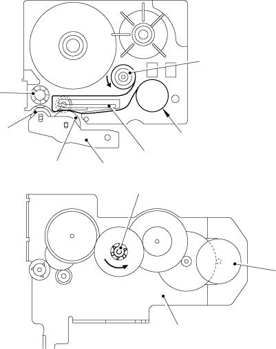
(2)Adhesive Base Tape Feeding (only for laminated tape cassettes)
A laminated tape cassette contains both a transparent laminate tape roll and a separate adhesive base tape roll.
When a transparent laminate tape and an adhesive base tape pass through the contact point (between the tape feed roller and tape feed sub roller), they are then bonded together into a single, printed tape. The ink printed on the laminate tape is, therefore, sealed up with the adhesive base tape.
(3)Ink Ribbon Feeding (except for non-laminated thermal film tape cassettes and stamp tape cassettes)
As the DC motor rotates, the ribbon drive cam located at the middle of the gear train rotates counterclockwise. When fitted on the ribbon drive cam, the ribbon take-up roll in the tape cassette also rotates to take up the ink ribbon.
To apply proper tension to the ink ribbon between the platen and the ribbon drive cam, the feed amount of the ribbon drive cam is slightly greater than that of the tape feed gear. The difference between the tape feed speeds at the platen and at the ribbon drive cam is absorbed by the clutch spring which is integrated in the ribbon drive cam and allows the cam to slip.
This way, the ink ribbon is kept tense, which enables the ribbon to clearly separate from the tape at the stabilized angle after printing.
Ribbon take-up roll
Tape feed roller
Tape feed sub roller
Ink ribbon
Head ASSY
Platen roller |
Roller holder ASSY |
|
|
|
Ribbon drive cam |
DC motor
Chassis ASSY
Fig. 2.1-4 Ribbon Feeding Mechanism
II-5

2.1.4Automatic Tape Cutter Mechanism
The cutter ASSY consists of a stationary blade and a movable blade driven by the cutter motor.
Upon completion of printing and tape feeding, the CPU activates the cutter motor whose clockwise rotation is transmitted via the idle gears to the cutter moving gear.
As the cutter moving gear rotates counterclockwise, its boss "X" (which is fitted in the opening of the movable blade) actuates the movable blade to pivot it around shaft "Y." Consequently, the cutter cuts the printed tape routing through the movable and stationary blades, just like a scissors.
After that, the CPU keeps the cutter motor on. When the movable blade comes back to the home position, its end "Z" activates the cutter sensor actuator which presses the cutter sensor. The moment the CPU receives the sensor signal, it stops the cutter motor.
Cutter double gear
Stationary blade
Cutter motor
Full cutter sensor PRO ASSY
Tape
“Y” Movable blade
“X”
Cutter moving gear
“Z” Actuator
Fig. 2.1-5 Automatic Tape Cutter Mechanism
II-6

2.1.5Roller Holder ASSY & Cassette Cover Interlocking Mechanism
Closing the cassette cover pushes down the roller release lever and brings the top of the lever into the hooked section provided on the inside of the cassette cover.
As described in Subsection 2.1.2 “Roller Holder ASSY Setting & Retracting Mechanism”, the roller release lever shifts the roller holder release rod so that the roller holder ASSY is pressed towards the head ASSY side.
Tape cassette |
Head ASSY |
|
Shaft
Platen roller Tape feed sub roller
Chassis ASSY
Roller release lever
Roller holder ASSY
Roller holder release rod
Roller release lever
Roller holder release spring
|
Roller holder |
|
|
release rod |
|
(Roller Holder ASSY retracted) |
(Roller Holder ASSY engaged) |
|
Fig. 2.1-6 |
Roller Release Lever and Roller Holder Release Rod |
|
Hooked section |
Cassette cover |
|
Cassette cover
Fig. 2.1-7 Roller Holder ASSY & Cassette Cover Interlocking Mechanism
Opening the cassette cover pulls up the roller release lever placed in the hooked section of the cassette cover, which shifts the roller holder release rod so that the roller holder ASSY is retracted from the head ASSY side by the platen lower spring.
II-7

2.2DISASSEMBLY & REASSEMBLY
2.2.1Disassembly Procedure
[ 1 ] Removing the Battery Lid and Batteries
(1)Turn the machine upside down.
(2)Press section "A" of the battery lid to remove, then take out batteries.
Section “A”
Battery lid
Bottom cover
Batteries
Bottom cover
Fig. 2.2-1 Removing the Battery Lid and Batteries
II-8
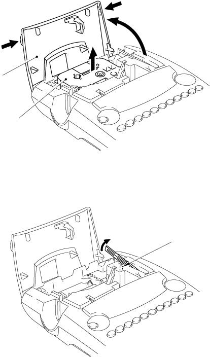
[ 2 ] Removing the Tape Cassette and Tape Separator Stick
(1)Place the machine rightside up and open the cassette cover fully.
(2)Pull the tape cassette up and out of the machine.
Cassette cover
Tape cassette
Fig. 2.2-2 Removing the Tape Cassette
(3)Pull the tape separator stick up.
Hook
Fig. 2.2-3 Removing the Tape Separator Stick
II-9
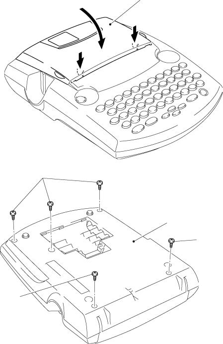
[ 3 ] Removing the Bottom Cover
(1)Close the cassette cover while pressing down section "B."
(2)Turn the machine upside down.
(3)Remove five screws from the bottom cover.
(4)Apply your fingers to the bottom cover and pull it up.
Cassette cover
Section “B”
Section “B”
Screws
Bottom cover
Screw
Screw
Fig. 2.2-4 Removing the Bottom Cover (1)
II-10
(5)Separate the bottom cover from the upper cover.
(6)Open the bottom cover to the left as shown below.
(7)Attach the tweezers onto the positive (+) and negative (-) terminals in order to discharge the capacitor mounted on the main PCB.
(8)Disconnect the power supply harness from the main PCB.
(9)Disconnect the USB/IF harness from the main PCB (PT-2300/2310).
(10)Release the grounding wire from the rib provided on the upper cover and remove the screw that secures the grounding wire to the chassis ASSY.
(PT-2300/2310)
Tweezers
Positive (+) terminal
Negative (-) |
USB/IF |
harness |
|
terminal |
(Front) |
|
|
|
Power supply harness |
(PT-2450)
Tweezers
Positive (+) terminal
(Front)
Negative (-) terminal
Power supply harness
Bottom cover
Screw
Grounding wire
Upper cover
Main PCB
Bottom cover
Screw
Grounding wire
Upper cover
Main PCB
Fig. 2.2-5 Removing the Bottom Cover (2)
Note: Check that the lower feet are tightly attached to the bottom cover without any gaps, peeling-off, or overreaching.
II-11

[ 4 ] Removing the Cassette Cover, Chassis ASSY and Shield Plate
CAUTION: During the following job, handle the connectors and harnesses gently so as not to damage them.
(1)Take off the cassette cover from the upper cover. The roller release lever will pop up.
Cassette cover
Roller release lever
Upper cover
Fig. 2.2-6 Removing the Cassette Cover
(2)Remove the switch ASSY harness which is soldered at 6 places, from the main PCB.
Note: However, if only the chassis ASSY is removed, the soldered switch ASSY must not be removed.
Switch ASSY harness
Main PCB
Upper cover
Fig. 2.2-7 Removing the Chassis ASSY and Shield Plate (1)
II-12

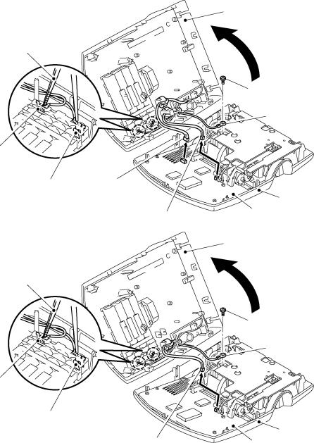
(4)Disconnect the following harnesses from the main PCB.
-Cutter motor harness
-Full cutter sensor harness
-Photo interrupter harness
(5)Remove the harness the main PCB by melting the solder.
-DC motor harness
(6)Disconnect the head cable from the main PCB.
(7)Remove the two screws of the chassis ASSY.
(8)Remove the shield plate from the chassis ASSY.
(9)Lift the chassis ASSY up and out of the upper cover.
Screws
Shield Plate
DC motor harness
Chassis ASSY
Photo interrupter harness
Head cable
Full cutter sensor harness
Cutter motor harness
Upper cover
Main PCB
Fig. 2.2-8 Removing the Chassis ASSY and Shield Plate (2)
II-13
 Loading...