

2 609 932 287 - Buch Seite 1 Mittwoch, 22. Oktober 2003 1:58 13
Bedienungsanleitung
Operating instructions
Instructions d’emploi
Instrucciones de servicio
Manual de instruções
Istruzioni d’uso
Gebruiksaanwijzing
Betjeningsvejledning
Bruksanvisning
Brukerveiledningen
Käyttöohje
Οδηγία χειρισµού
Kullan∂m k∂lavuzu
PSR 9,6 VE-2
PSR 12 VE-2
PSR 14,4 VE-2
* Des idées en action.
PSR 18 VE-2
Deutsch
English
Français
Español
Português
Italiano
Nederlands
Dansk
Svenska
Norsk
Suomi
Eλληvικά
Türkçe
2 609 932 287 - Buch Seite 1 Mittwoch, 22. Oktober 2003 1:58 13
10
1
2
3
9
4
5
6
PSR 9,6 VE-2
PSR 12 VE-2
PSR 14,4 VE-2
PSR 18 VE-2
A
6
8
7
B
2 • 2 609 932 287 • 03.10
12 11
13
2 609 932 287 - Buch Seite 1 Mittwoch, 22. Oktober 2003 1:58 13
C
14
E
➊➋
D
14
F
➌ ➍ ➎
G
➏
➐
3 • 2 609 932 287 • 03.10
H
➒ ➓
➑
2
3
4
5
6
7
8
9
*
■
■
■
■
2 609 932 287 - Buch Seite 1 Mittwoch, 22. Oktober 2003 1:58 13
Gerätekennwerte
Akku-Bohrschrauber PSR 9,6 VE-2 PSR 12 VE-2 PSR 14,4 VE-2 PSR 18 VE-2
Bestellnummer 0 603 943 6.. 0 603 943 5.. 0 603 943 4.. 0 603 943 3..
Leerlaufdrehzahl
1. Gang [min
2. Gang [min
Drehmomenteinstellbereich [Nm] 0,7 –9,0 0,7 –9,0 0,7– 9,0 0,7 – 9,0
max. Drehmoment harter/
weicher Schraubfall nach
ISO 5393
max. Bohr-Ø (1./2. Gang)
Stahl [mm] 10/8 10/10 10/10 12/12
Holz [mm] 18/16 20/19 28/20 30/ 22
Schrauben-Ø, max. [mm] 6 6 7 8
Bohrfutterspannbereich [mm] 1–10 1–10 1–10 1–10
Bohrspindelgewinde 3/8" 3/8" 3/8" 3/8"
Gewicht ohne Akku, ca. [kg] 1,0 1,0 1,0 1,2
Akku
Temperaturüberwachung NTC NTC NTC NTC
Nennspannung [V=] 9,6 12 14,4 18
Kapazität [Ah] 1,5 1,5 1,5 1,5
Gewicht, ca. [kg] 0,5 0,6 0,75 1,0
Bitte die Bestellnummer Ihrer Maschine beachten. Die Handelsbezeichnungen einzelner Maschinen können variieren.
-1
] 0 – 390 0 – 390 0 – 400 0 – 400
-1
] 0 – 1 250 0–1 250 0–1 250 0 – 1 250
[Nm] 22/8 24/12 30/16 42/22
Geräteelemente
1 Gangwahlschalter
Drehmoment-Einstellring
Schnellspannbohrfutter
Ein-/Ausschalter
Drehrichtungsumschalter
Schrauberklinge*
Akku*
Akku-Entriegelungstaste
Softgrip
10 Akku-Schrauber Display
11 Schraubendrehereinsatz (Bit)*
12 Universalbithalter*
13 Sicherungsschraube
14 Innensechskantschlüssel*
Abgebildetes oder beschriebenes Zubehör gehört
teilweise nicht zum Lieferumfang.
Bestimmungsgemäßer Gebrauch
Das Gerät ist bestimmt zum Eindrehen und Lösen von Schrauben sowie zum Bohren in Holz,
Metall, Keramik und Kunststoff.
4 • 2 609 932 287 • 03.10
Deutsch - 1
Zu Ihrer Sicherheit
Gefahrloses Arbeiten mit dem
Gerät ist nur möglich, wenn Sie
die Bedienungsanleitung und
die Sicherheitshinweise vollständig lesen und die darin ent-
folgen. Zusätzlich müssen die allgemeinen
Sicherheitshinweise im beigefügten Heft befolgt werden.
Schutzbrille tragen.
Bei langen Haaren Haarschutz tragen. Nur mit
eng anliegender Kleidung arbeiten.
Vor jeder Benutzung Gerät und Akku überprü-
fen. Werden Schäden festgestellt, Gerät nicht
weiter benutzen. Reparatur nur von einem
Fachmann durchführen lassen. Gerät nie
selbst öffnen.
Vor allen Arbeiten am Gerät (z. B. Wartung,
Werkzeugwechsel, usw.) sowie bei dessen
Transport und Aufbewahrung den Drehrichtungsumschalter stets in Mittelstellung
bringen.
unbeabsichtigtem Betätigen des Ein-/Ausschalters.
haltenen Anweisungen strikt be-
Sonst besteht Verletzungsgefahr bei
A
■
■
■
2 609 932 287 - Buch Seite 2 Mittwoch, 22. Oktober 2003 1:58 13
■
■
■
■
■
■
■
7
8
■
3
3
7
4
4
4
4
■ Überzeugen Sie sich vor der Benutzung vom
sicheren Sitz des Akkus im Gerät.
Verwenden Sie geeignete Suchgeräte, um
verborgene Versorgungsleitungen aufzuspüren, oder ziehen Sie die örtliche Versorgungsgesellschaft hinzu.
Kontakt mit Elektroleitungen kann zu Feuer
und elektrischem Schlag führen.
Beschädigung einer Gasleitung kann zur Explosion führen. Eindringen in eine Wasserleitung verursacht Sachbeschädigung.
Gerät gut festhalten: Beim Festziehen können
kurzzeitig hohe Reaktionsmomente auftreten.
Sichern Sie das Werkstück. Ein mit Spann-
vorrichtungen oder Schraubstock festgehaltenes Werkstück ist sicherer gehalten als mit Ihrer Hand.
Niemals Kindern die Benutzung des Gerätes
gestatten.
Bosch kann nur dann eine einwandfreie Funktion des Gerätes zusichern, wenn das für dieses Gerät vorgesehene Original-Zubehör verwendet wird.
Akku und Ladegerät
Unbedingt die beiliegende Bedienungsanleitung des Ladegerätes lesen!
Akku nicht öffnen sowie vor Stoß schützen.
Trocken und frostsicher aufbewahren.
Erwärmten Akku vor dem Laden abkühlen lassen.
Akku vor Hitze und Feuer schützen: Explosionsgefahr! Akku nicht auf Heizkörper ablegen
oder längere Zeit starker Sonneneinstrahlung
aussetzen, Temperaturen über 50 °C schaden.
Den Akku nicht in den Hausmüll, ins Feuer
oder ins Wasser werfen.
Vor der Inbetriebnahme
Akku laden
Ein neuer oder längere Zeit nicht verwendeter
Akku bringt erst nach ca. 5 Lade- und Entladezyklen seine volle Leistung.
Zur Entnahme des Akkus
drücken und den Akku nach unten heraus-
ten
ziehen. Keine Gewalt anwenden.
Der Akku ist mit einer NTC-Temperaturüberwachung ausgestattet, welche Ladung nur im Temperaturbereich zwischen 0 °C und 45 °C zulässt.
Dadurch wird eine hohe Akku-Lebensdauer erreicht.
die Entriegelungstas-
Eine wesentlich verkürzte Betriebszeit nach der
Aufladung zeigt an, dass die Akkus verbraucht
sind und ersetzt werden müssen.
Hinweise zum Umweltschutz beachten.
Werkzeugwechsel
Das Bohrfutter
Werkzeug eingesetzt werden kann. Das Werkzeug einsetzen.
Die Hülse des Schnellspannbohrfutters
Hand kräftig zudrehen. Das Bohrfutter wird dadurch automatisch verriegelt.
Drehen Sie die Hülse in Gegenrichtung um das
Werkzeug zu entnehmen.
durch Drehen öffnen, bis das
von
Schrauben (siehe Bild )
Die Schrauberklinge 6 direkt in das Bohrfutter
einspannen oder bei Verwendung von Schraubendrehereinsätzen (Bits)
versalbithalter
12 verwenden.
11 zusätzlichen Uni-
Inbetriebnahme
Akku einsetzen
Den Drehrichtungsumschalter 5 auf Mitte = Einschaltsperre stellen und den geladenen Akku
den Griff einrasten lassen.
in
Ein-/Ausschalten
Zur Inbetriebnahme des Gerätes den Ein-/Ausschalter
Zum
schalter
drücken und gedrückt halten.
Die Maschine läuft je nach Druck
auf den Ein-/Ausschalter
abler Drehzahl zwischen 0 und Maximum. Leichter Druck bewirkt eine
kleine Drehzahl und macht somit
einen sanften, kontrollierten Anlauf
möglich. Das Gerät nicht so stark
belasten, dass es zum Stillstand
kommt.
Ausschalten des Gerätes den Ein-/Aus-
loslassen.
mit vari-
Mechanische Gangwahl
Mit dem Gangwahlschalter 1 können zwei Drehzahlbereiche vorgewählt werden:
1. Gang: Niedrige Drehzahl, große Kraft.
2. Gang: Hohe Drehzahl, geringere Kraft.
Die Gänge dürfen nur bei stillstehender Ma-
schine umgeschaltet werden. Rastet der Gang
nicht ganz ein, kurz den Ein-/Ausschalter
cken.
drü-
5 • 2 609 932 287 • 03.10
Deutsch - 2
2 609 932 287 - Buch Seite 3 Mittwoch, 22. Oktober 2003 1:58 13
5
4
7
➯
Vollautomatische Spindelarretierung
(Auto-Lock)
Bei nicht gedrücktem Ein-/Ausschalter 4 wird die
Bohrspindel arretiert.
Dies ermöglicht ein schnelles, bequemes und
einfaches Wechseln des Einsatzwerkzeuges im
Bohrfutter.
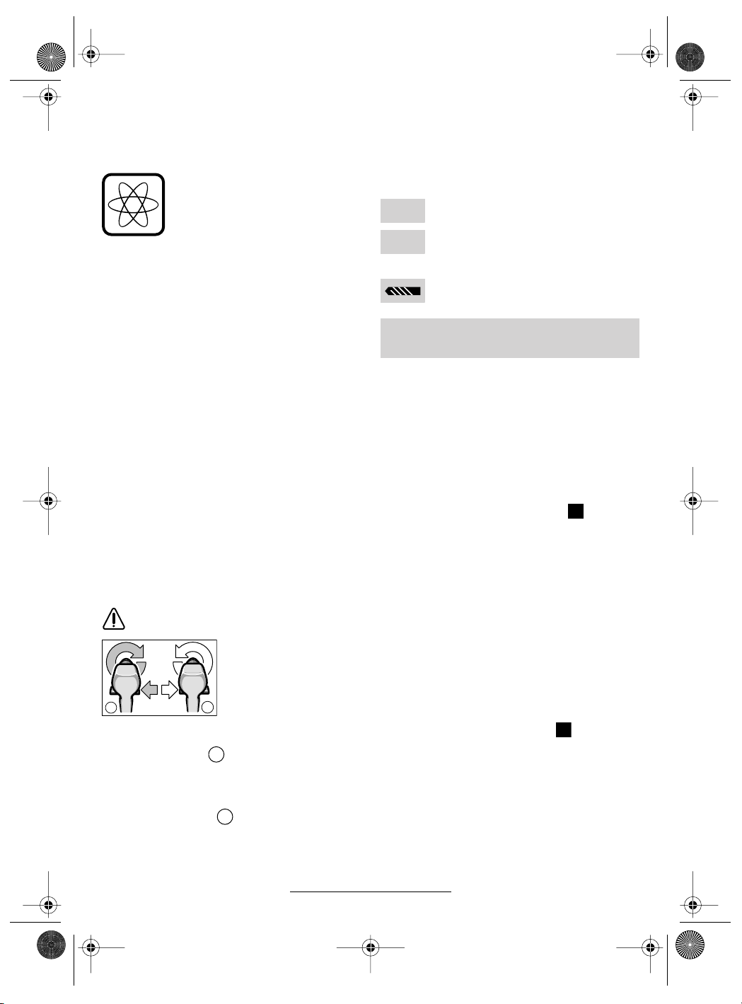
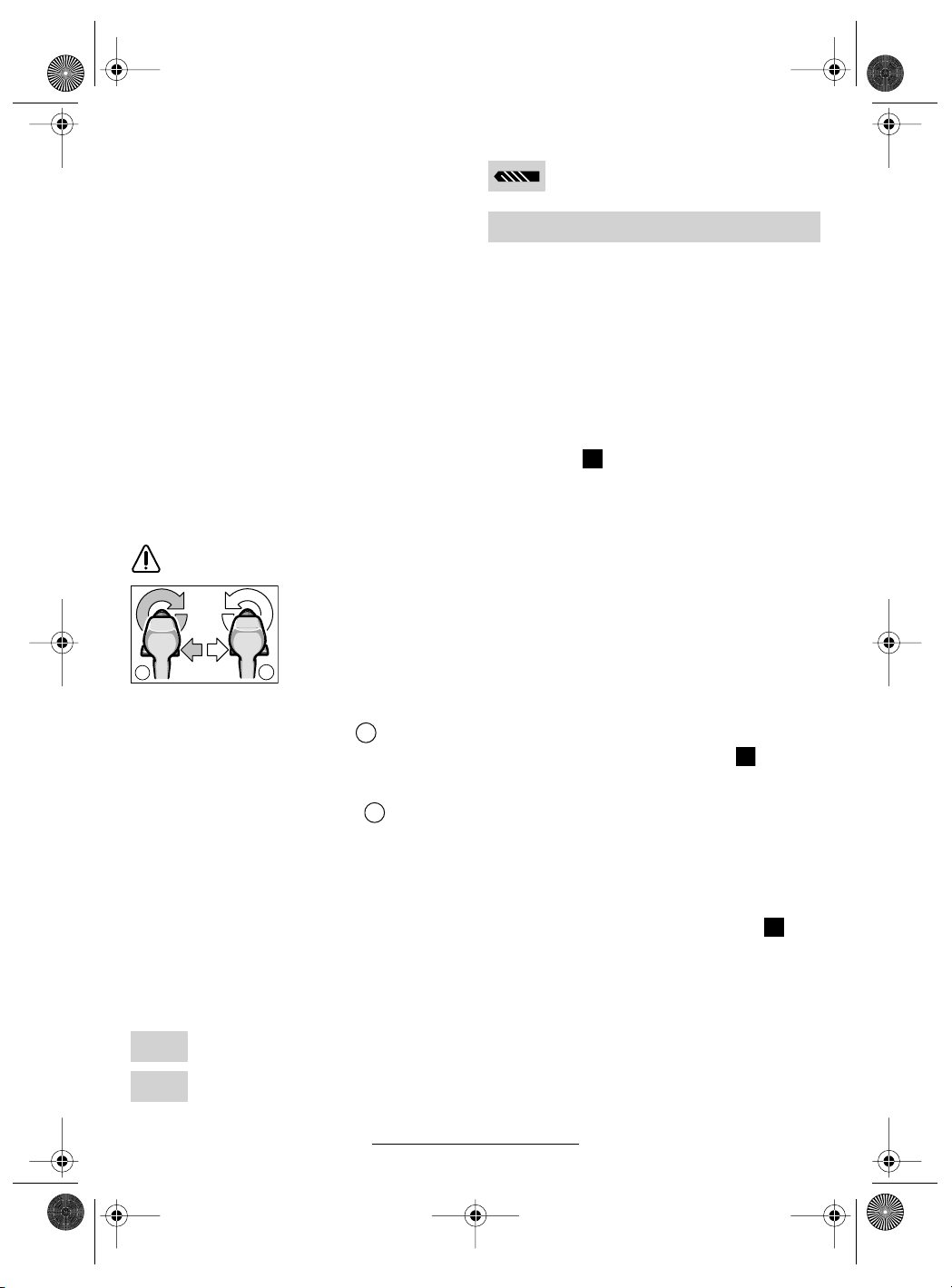
Umschalten der Drehrichtung
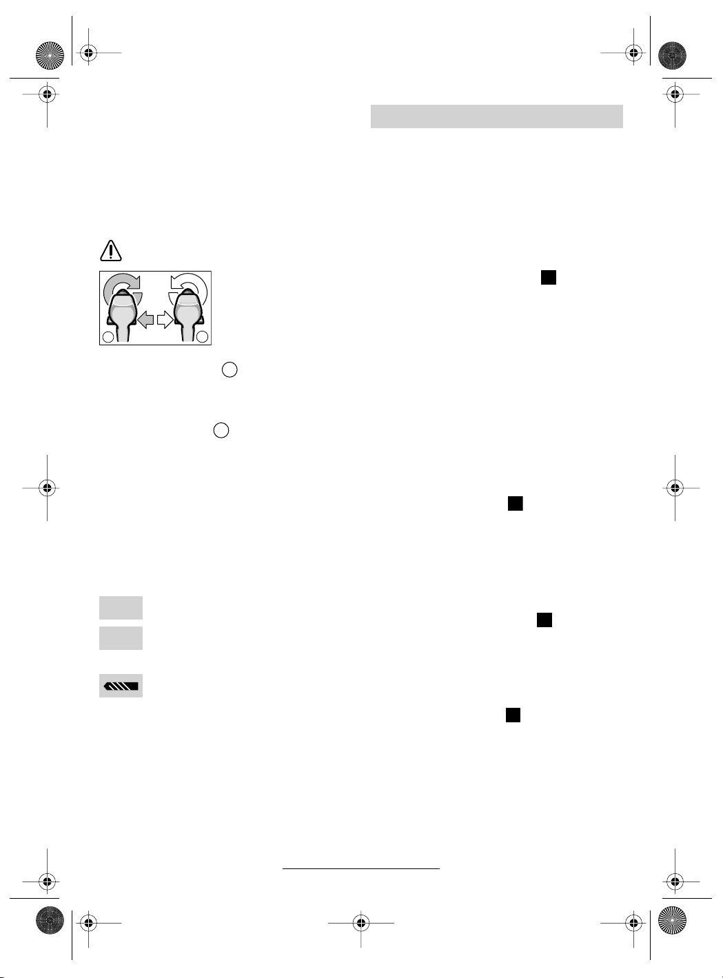
Den Drehrichtungsumschalter 5 nur bei
Stillstand betätigen.
Mit dem Drehrichtungsumschalter
Drehrichtung der Maschine umgeschaltet. Bei
a
Drehrichtung rechts ( )
Den Drehrichtungsumschalter nach links bis zum
Anschlag durchdrücken (Normalbetrieb: Bohren,
Eindrehen von Schrauben etc.).
Drehrichtung links ( )
Den Drehrichtungsumschalter nach rechts bis
zum Anschlag durchdrücken (Lösen bzw. Herausdrehen von Schrauben und Muttern).
betätigtem Ein-/Aus-
b
schalter
nicht möglich.
a
b
wird die
ist dies jedoch
Drehmoment einstellen
Bei richtiger Einstellung des Drehmoments öffnet
die Überrastkupplung, sobald die Schraube bündig in das Material eingedreht bzw. das eingestellte Drehmoment erreicht ist. Beim Herausdrehen eine höhere Einstellung wählen, bzw. auf
das Symbol „Bohren“ stellen.
Schwache Einstellung, z. B. kleine
1
Schrauben, weiche Werkstoffe.
Starke Einstellung, z. B. große Schrau-
25
ben, harte Werkstoffe.
Bohren
Den Drehmoment-Einstellring 2 auf das
Symbol „Bohren“ stellen.
Akku-Schrauber Display
Das Display
aktiviert.
Nach einiger Zeit schaltet sich das Display in den
Standby-Modus. Das Display
setzen des Akkus
beiden Tasten am Display wieder aktiviert werden.
Bei Temperaturen unter 0 °C ist die Funktion des
Displays eingeschränkt.
Warnhinweise (siehe Bild )
Die Funktion der Warnhinweise ist auch im
Standby-Modus gegeben.
➊
Der Akku ist fast entladen:
Der Motor ist überhitzt:
➋
➯ Schalten Sie das Gerät ab oder lassen Sie
es einige Zeit unbelastet im Leerlauf laufen,
um es abzukühlen. Warten Sie, bis die Anzeige erlischt.
10 wird beim Einsetzen des Akkus 7
10 kann durch Ein-
oder durch Drücken einer der
E
Laden Sie den Akku auf.
Einstellungshilfe
Die Anzeige dient der Orientierung. Die Werte
sind durch einen praktischen Versuch zu überprüfen.
Materialwahl (siehe Bild )
Wählen Sie das zu bearbeitende Material durch
(mehrfaches) Drücken der linken Taste aus:
F
➌ Stahl
➍ Weichholz
➎ Hartholz
Das Beispiel zeigt: Hartholz.
Anwendungswahl (siehe Bild )
Wählen Sie den Anwendungsfall durch (mehrfaches) Drücken der rechten Taste aus:
G
➏+➑ Schraube eindrehen (4 Durchmesserbe-
reiche)
➐+➑ Loch bohren (2 Durchmesserbereiche)
Empfehlung (siehe Bild )
Die Anzeige liefert eine Empfehlung für die optimale Einstellung Ihres Akku-Bohrschraubers.
Stellen Sie die vorgeschlagenen Werte an Ihrem
Akku-Bohrschrauber ein.
H
➒ 1. Gang/ 2. Gang
➓ Drehmomentbereich (Stufe 1–5, 5 – 15,
15–25, „Bohren“)
Das Beispiel zeigt: 2. Gang, Drehmomentbereich 5–15.
6 • 2 609 932 287 • 03.10
Deutsch - 3

2 609 932 287 - Buch Seite 4 Mittwoch, 22. Oktober 2003 1:58 13
Bohrfutter wechseln
■ Vor allen Arbeiten am Gerät den Akku her-
ausnehmen.
Das Bohrfutter ist gegen das Lösen von der Bohrspindel mit der Sicherungsschraube 13 gesichert.
Das Bohrfutter ganz öffnen und die Sicherungsschraube 13 durch Drehen im Uhrzeigersinn vollständig herausschrauben (siehe Bild ).
Bohrfutter lösen (siehe Bild )
Die Maschine auf eine standfeste Unterlage
(z. B. Werkbank) legen. Die Maschine festhalten
und das Bohrfutter wie eine Schraube durch
Linksdrehen lösen (
futter wird durch einen Schlag auf den langen
Schaft des Innensechskantschlüssels 14 gelöst.
➊). Ein festsitzendes Bohr-
Bohrfutter festziehen (siehe Bild )
Die Montage des Bohrfutters erfolgt in umgekehrter Reihenfolge (
).
➋
B
C
D
Arbeitshinweise
Softgrip
Die rückseitig angebrachte Griff-Fläche 9 (Softgrip) erhöht die Abrutschsicherheit und sorgt dadurch für bessere Griffigkeit und Handlichkeit des
Gerätes.
Durch die Gummierung wird gleichzeitig eine vibrationshemmende Wirkung erzielt.
Tipps
■ Verwenden Sie nur zum Schraubenkopf passende Schrauberklingen/Bits.
■ Bei Eindrehen größerer, längerer Schrauben
in harten Werkstoffen am besten vorbohren.
■ Beim Bohren in Metall nur einwandfreie geschärfte HSS-Bohrer (HSS = HochleistungsSchnell-Schnittstahl) verwenden. Entsprechende Qualität garantiert das Bosch-Zubehör-Programm.
Wartung und Reinigung
■ Vor allen Arbeiten am Gerät den Akku her-
ausnehmen.
■ Gerät und Lüftungsschlitze stets sauber
halten, um gut und sicher zu arbeiten.
Sollte das Gerät trotz sorgfältiger Herstellungsund Prüfverfahren einmal ausfallen, ist die Reparatur von einer autorisierten Kundendienststelle
für Bosch-Elektrowerkzeuge ausführen zu lassen.
Bei allen Rückfragen und Ersatzteilbestellungen
bitte unbedingt die 10-stellige Bestellnummer laut
Typenschild des Gerätes angeben.
Umweltschutz
Rohstoffrückgewinnung statt
Müllentsorgung
Gerät, Zubehör und Verpackung
sollten einer umweltgerechten Wiederverwertung zugeführt werden.
Diese Anleitung ist aus chlorfrei gefertigtem Recycling-Papier hergestellt.
Zum sortenreinen Recycling sind Kunststoffteile
gekennzeichnet.
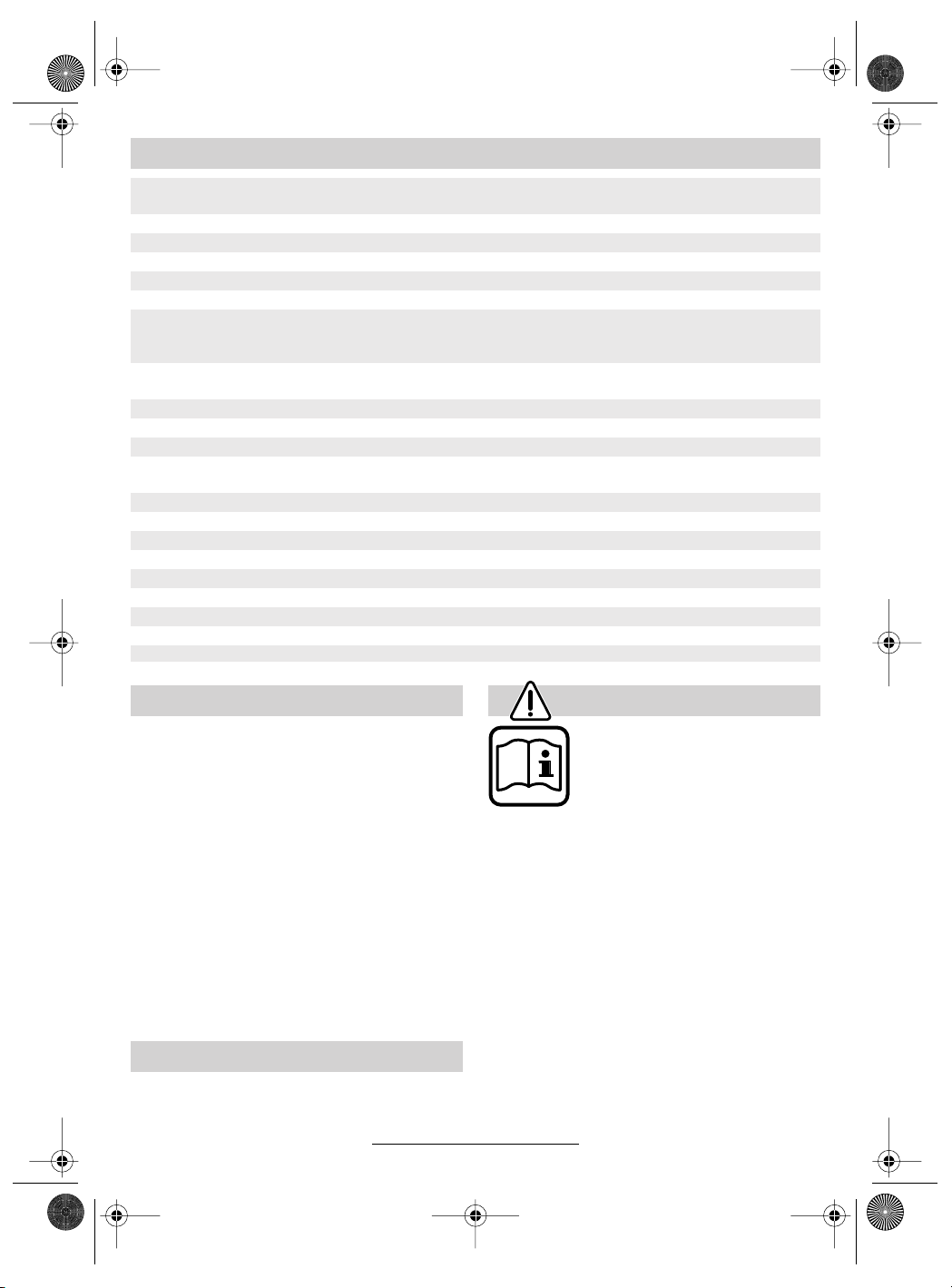
Nickel-Cadmium-Akku:
Wenn Ihr Produkt mit einem Nickel-CadmiumAkku ausgerüstet ist,
muss der Akku gesammelt, recycelt oder auf
umweltfreundliche Weise
entsorgt werden.
Defekte oder verbrauchte Akkus müssen gemäß
Richtlinie 91/157/EWG recycelt werden.
Nicht mehr gebrauchsfähige Akkus/Batterien
können direkt abgegeben werden bei:
Deutschland
Recyclingzentrum Elektrowerkzeuge
Osteroder Landstraße 3
37589 Kalefeld
Schweiz
Batrec AG
3752 Wimmis BE
In Deutschland sind nicht mehr gebrauchsfähige
Geräte zum Recycling beim Handel abzugeben
oder (ausreichend frankiert) direkt einzuschicken
an:
Recyclingzentrum Elektrowerkzeuge
Osteroder Landstraße 3
37589 Kalefeld
7 • 2 609 932 287 • 03.10
Deutsch - 4
2 609 932 287 - Buch Seite 5 Mittwoch, 22. Oktober 2003 1:58 13
Geräusch-/Vibrationsinformation Service und Kundenberater
Messwerte ermittelt entsprechend EN 50 260.
Der A-bewertete Schalldruckpegel des Gerätes
ist typischerweise kleiner als 70 dB (A).
Der Geräuschpegel beim Arbeiten kann
85 dB (A) überschreiten.
Gehörschutz tragen!
Die Hand-Arm-Vibration ist typischerweise niedriger als 2,5 m/s
2
.
Explosionszeichnungen und Informationen
zu Ersatzteilen finden Sie unter:
www.bosch-pt.com
www.powertool-portal.de, das Internetportal
für Heimwerker und Gartenfreunde
www.dha.de, das komplette Service-Angebot
der Deutschen Heimwerker Akademie
Deutschland
Robert Bosch GmbH
Servicezentrum Elektrowerkzeuge
Zur Luhne 2
37589 Kalefeld
✆ Service: ....................................... 01 80 - 3 35 54 99
........................................... +49 (0) 55 53 / 20 22 37
Fax:
✆ Kundenberater: ...................... 01 80 - 3 33 57 99
Österreich
ABE Service GmbH
Jochen-Rindt-Straße 1
1232 Wien
✆ Service: ..................................... +43 (0)1 / 61 03 80
............................................... +43 (0)1 / 61 03 84 91
Fax:
✆ Kundenberater:............ +43 (0)1 / 797 22 3066
E-Mail: abe@abe-service.co.at
8 • 2 609 932 287 • 03.10
Schweiz
✆ Service: ................................. +41 (0)1 / 8 47 16 16
Fax:
✆ Kundenberater:...... Grüne Nr. 0 800 55 11 55
Wir erklären in alleiniger Verantwortung, dass dieses Produkt mit den folgenden Normen oder normativen Dokumenten übereinstimmt: EN 50 260
(Akku-Geräte) bzw. EN 60 335 (Akku-Ladegeräte) gemäß den Bestimmungen der Richtlinien
73/23/EWG, 89/336/EWG, 98/37/EG.
Dr. Egbert Schneider Dr. Eckerhard Strötgen
Senior Vice President Head of Product
Engineering Certification
Robert Bosch GmbH, Geschäftsbereich Elektrowerkzeuge
Änderungen vorbehalten
Deutsch - 5
.................................................. +41 (0)1 / 8 47 16 57
Konformitätserklärung
03
2 609 932 287 - Buch Seite 1 Mittwoch, 22. Oktober 2003 1:58 13
Tool Specifications
Cordless screwdriver PSR 9,6 VE-2 PSR 12 VE-2 PSR 14,4 VE-2 PSR 18 VE-2
Order number 0 603 943 6.. 0 603 943 5.. 0 603 943 4.. 0 603 943 3..
No-load speed
1st gear [rpm] 0– 390 0– 390 0 –400 0 – 400
2nd gear [rpm] 0– 1 250 0–1 250 0 – 1 250 0 – 1 250
Torque adjustment range [Nm] 0.7 –9.0 0.7– 9.0 0.7 – 9.0 0.7 –9.0
max. torque for hard/soft
screwdriving application
according to ISO 5393
Maximum drilling Ø
(1st/2nd gear)
Steel [mm] 10/8 10/10 10/ 10 12/ 12
Wood [mm] 18/16 20/19 28 / 20 30/22
Screw diameter, max. [mm] 6 6 7 8
Chuck clamping range [mm] 1–10 1–10 1–10 1–10
Drill spindle thread 3/8" 3/8" 3/8" 3/8"
Weight without battery,
approx.
Battery
Temperature control NTC NTC NTC NTC
Rated voltage [V=] 9.6 12 14.4 18
Capacity [Ah] 1.5 1.5 1.5 1.5
Weight, approx. [kg] 0.5 0.6 0.75 1.0
Please observe the order number of your machine. The trade names of the individual machines may vary.
[Nm] 22/8 24/12 30/ 16 42/ 22
[kg] 1.0 1.0 1.0 1.2
Machine Elements
1 Gear selector
2 Torque setting ring
3 Keyless chuck
4 On/Off switch
5 Rotational direction switch
6 Screwdriver bit*
7 Battery*
8 Battery unlocking button
9 Soft grip
10 Display
11 Screwdriver attachment (bit)*
12 Universal bit holder*
13 Locking screw
14 Allen key*
* Not all of the accessories illustrated or described are
included as standard delivery.
Intended Use
The machine is intended for the screwing in and
loosening of screws as well as for drilling in wood,
metal, ceramic and plastic.
9 • 2 609 932 287 • 03.10
English - 1
For Your Safety
Working safely with this machine is possible only when the
operating and safety information
are read completely and the instructions contained therein are
strictly followed. In addition, the
general safety notes in the enclosed booklet
must be observed.
■ Wear safety goggles.
■ For long hair, wear hair protection. Work only
with closely fitting clothes.
■ Before each use, check the machine and bat-
tery. If damage is detected, do not use the machine. Have repairs performed only by a qualified technician. Never open the machine yourself.
■ Before any work on the machine itself (e. g.
maintenance, tool change, etc.) as well as
when transporting and storing, always set
the rotational direction switch to the centre
position. Otherwise danger of injury is given
when unintentionally actuating the On/Off
switch.
2 609 932 287 - Buch Seite 2 Mittwoch, 22. Oktober 2003 1:58 13
■ Convince yourself before using that the battery
is securely seated in the machine.
■ Use appropriate detectors to determine if
utility lines are hidden in the work area or
call the local utility company for assistance.
Contact with electric lines can lead to fire and
electric shock. Damaging a gas line can lead
to explosion. Penetrating a water line causes
property damage.
■ Hold the machine tightly: When driving in
screws, high reaction moments can briefly occur.
■ Secure the workpiece. A workpiece clamped
with clamping devices or in a vice is held more
secure than by hand.
■ Never allow children to use the machine.
■ Bosch is only able to ensure perfect operation
of the machine if the original accessories intended for it are used.
Battery and Battery Charger
■ The enclosed operating instructions for the
battery charger must be read carefully!
■ Do not open the battery, and protect it from impact. Store in a dry and frost-free place.
■ Allow a heated battery to cool before charging.
■ Protect the battery from heat and fire: Danger
of explosion! Do not place the battery on radiators or expose to strong sun rays for a longer
time; temperatures over 50 °C cause damage.
■ Do not dispose of the battery in household
waste or discard into fire or water.
Before Putting into Operation
Battery Charging
A battery that is new or has not been used for a
longer period does not develop its full capacity
until after approximately 5 charging/discharging
cycles.
To remove the battery 7, press the unlocking buttons 8 and pull out the battery downwards. Do not
exert any force.
The battery is equipped with an NTC temperature
control which allows charging only within a temperature range of between 0 °C and 45 °C. A long
battery service life is achieved in this manner.
A significantly reduced working period after
charging indicates that the batteries are used and
must be replaced.
■ Observe the notes on environmental protection.
10 • 2 609 932 287 • 03.10
English - 2
Changing the Tool
Open the drill chuck 3 by turning until the tool can
be inserted. Insert the tool.
Firmly tighten the sleeve of the keyless chuck 3
by hand. This automatically locks the chuck.
Rotate the sleeve in the reverse direction to remove the tool.
Screwdriving (see figure )
Directly clamp the screwdriver bit 6 into the drill
chuck or use the additional universal bit holder 12
when operating with hex shank bits 11.
A
Initial Operation
Inserting the Battery
Set the rotational direction switch 5 to the centre
position = lock-off and allow the charged battery 7 to engage into the handle.
Switching On and Off
To start the machine, press the On/Off switch 4
and keep it depressed.
The machine runs with variable
speed between 0 and maximum,
depending on the pressure applied
to the On/Off switch 4. Light pressure results in a low rotational
speed thus allowing smooth, controlled starts. Do not strain the machine so heavily that it comes to a
standstill.
To switch off the machine, release the On/Off
switch 4.
Gear Selection, Mechanical
Two speed ranges can be preselected with the
gear selector 1:
1st gear: Low rotational speed, high power.
2nd gear: High rotational speed, less power.
The speed settings may only be changed when
the machine is motionless. If the speed setting
has not quite notched in properly, briefly press
the On/Off switch 4.
2 609 932 287 - Buch Seite 3 Mittwoch, 22. Oktober 2003 1:58 13
Fully Automatic Spindle Locking
(Auto-Lock)
The drill spindle is locked when the On/Off
switch 4 is not pressed.
This makes quick and easy changing of the tool
in the drill chuck possible.
Reversing the Rotational Direction
Operate the rotational direction
switch 5 only at a standstill.
The rotational direction
switch 5 is used to reverse the rotational direction of the machine. How-
a
Right Rotation ( )
Turn the rotational direction switch through to the
left stop (normal operation: drilling, screwdriving,
etc.).
Left Rotation ( )
Press the rotational direction switch through to
the right stop (for loosening and unscrewing
screws and nuts).
ever, this is not possible
b
with the On/Off switch 4
actuated.
a
b
Setting the Torque
With the correct setting, the clutch disengages as
soon as the screw is driven flush into the material
or the set torque is reached. Select a higher setting when driving out screws, or set to the “Drilling” symbol.
Low setting, e. g., small screws, soft
1
materials.
High setting, e. g., large screws, hard
25
materials.
Drilling
Set the torque setting ring 2 to the “Drilling” symbol.
Cordless Screwdriver Display
The display 10 is activated when the battery 7 is
inserted.
After a while the display switches to the stand-by
mode. The display 10 can be activated again by
inserting the battery 7 or by pressing one of the
two push-button keys on the display.
For temperatures below 0 °C the function of the
display is limited.
Warning Indicators (see figure )
The function of the warning indicators is also operative in stand-by mode.
E
➊ The battery is almost empty:
➯ Recharge the battery.
The motor is starting to overheat:
➋
➯ Switch the machine off and allow to cool
down. Alternatively, run the machine at full
speed without load until the warning indicator
goes out.
Adjustment Aid
The display is for guidance. The settings are to
be checked by carrying out a practical test.
Material Selection (see figure )
Select the material to be worked by (multiple)
pressing of the left push-button key:
F
➌ Steel
➍ Softwood
➎ Hardwood
Shown in the example: Hardwood.
Application Selection (see figure )
Select the application by (multiple) pressing of
the right push-button key:
G
➏+➑ Driving in screws (4 Diameter ranges)
➐+➑ Drilling holes (2 Diameter ranges)
Recommendation (see figure )
The indication gives a recommendation for the
optimum setting of your cordless screwdriver. Adjust the proposed values on your cordless screwdriver.
H
➒ 1st gear/ 2nd gear
➓ Torque range (Level 1 – 5, 5– 15,
15 – 25, “Drilling”)
Shown in the example: 2nd gear; Torque
range 5 – 15.
11 • 2 609 932 287 • 03.10
English - 3
2 609 932 287 - Buch Seite 4 Mittwoch, 22. Oktober 2003 1:58 13
Replacing the Drill Chuck
■ Before any work on the machine itself, remove the battery.
The locking screw 13 secures the drill chuck
against loosening from the drill spindle. Fully
open the drill chuck and completely unscrew the
locking screw 13 by turning in clockwise direction
(see figure ).
B
Loosening the Drill Chuck
(see figure )
Place the machine on a stable surface (e. g.
workbench). Hold the machine firmly and loosen
the chuck by turning to the left, as when unscrewing a screw (
the long end of the Allen key 14 a sharp blow.
C
➊). Loosen a tight chuck by giving
Tightening the Drill Chuck
(see figure )
The drill chuck is mounted in reverse order (➋).
D
Operating Instructions
Soft grip
The gripping surface 9 on the rear of the handle
(soft grip) reduces the danger of slipping and
thereby improves the grip on the machine and the
handling.
At the same time, the rubber coating achieves a
vibration-reducing effect.
Tips
■ Use only screwdriver bits that fit properly in the
head of the screw.
■ When driving in larger and/or longer screws in
hard material, it is advisable to drill a pilot hole
first.
■ For drilling in metal, use only perfectly sharpened HSS drills. The appropriate quality is
guaranteed by the Bosch accessories program.
Maintenance and Cleaning
■ Before any work on the machine itself, remove the battery.
■ For safe and proper working, always keep
the machine and the ventilation slots clean.
If the machine should fail despite the care taken
in manufacturing and testing procedures, repair
should be carried out by an after-sales service
centre for Bosch power tools.
In all correspondence and spare parts orders,
please always include the 10-digit order number
given on the nameplate of the machine.
Environmental Protection
Recycle raw materials instead of disposing as
waste
The machine, accessories and packaging should
be sorted for environmental-friendly recycling.
These instructions are printed on recycled paper
manufactured without chlorine.
The plastic components are labelled for categorized recycling.
Nickel-cadmium-battery:
If your product is equipped
with a nickel-cadmium-battery, the battery must be
collected, recycled or disposed of in an environmentally-friendly way.
Defective or worn out batteries must be recycled
according to the guidelines 91/157/EEC.
Batteries no longer suitable for use can be
directly returned at:
Great Britain
Robert Bosch Ltd. (B.S.C.)
P.O. Box 98
Broadwater Park
North Orbital Road
Denham-Uxbridge
Middlesex UB 9 5HJ
✆ Service............................ +44 (0) 18 95 / 83 87 82
✆ Advice line.................... +44 (0) 18 95 / 83 87 91
............................................. +44 (0)18 95 / 83 87 89
Fax
12 • 2 609 932 287 • 03.10
English - 4
2 609 932 287 - Buch Seite 5 Mittwoch, 22. Oktober 2003 1:58 13
Noise/Vibration Information
Measured values determined according to
EN 50 260.
Typically the A-weighted sound pressure level of
the product is less than 70 dB (A).
The noise level when working can exceed
85 dB (A).
Wear hearing protection!
The typical hand/arm vibration is below 2.5 m/s
Service and Customer
Assistance
Exploded views and information on spare
parts can be found under:
www.bosch-pt.com
Great Britain
Robert Bosch Ltd. (B.S.C.)
P.O. Box 98
Broadwater Park
North Orbital Road
Denham-Uxbridge
Middlesex UB 9 5HJ
✆ Service............................ +44 (0) 18 95 / 83 87 82
✆ Advice line .................... +44 (0) 18 95 / 83 87 91
............................................. +44 (0) 18 95 / 83 87 89
Fax
Ireland
Beaver Distribution Ltd.
Greenhills Road
Tallaght-Dublin 24
✆ Service................................... +353 (0)1 / 414 9400
.................................................... +353 (0)1 / 459 8030
Fax
Australia
Robert Bosch Australia Ltd.
RBAU/SPT2
1555 Centre Road
P.O. Box 66 Clayton
3168 Clayton/Victoria
✆ ............................................... +61 (0)1 / 800 804 777
............................................... +61 (0)1 / 800 819 520
Fax
www.bosch.com.au
E-Mail: CustomerSupportSPT@au.bosch.com
New Zealand
Robert Bosch Limited
14-16 Constellation Drive
Mairangi Bay
Auckland
New Zealand
✆ ..................................................... +64 (0)9 / 47 86 158
..................................................... +64 (0)9 / 47 82 914
Fax
2
.
Declaration of Conformity
We declare under our sole responsibility that this
product is in conformity with the following standards or standardization documents. EN 50 260
(Battery powered products) and EN 60 335 (Battery charger) according to the provisions of the directives 73/23/EEC, 89/336/EEC, 98/37/EC.
03
Dr. Egbert Schneider Dr. Eckerhard Strötgen
Senior Vice President Head of Product
Engineering Certification
Robert Bosch GmbH, Geschäftsbereich Elektrowerkzeuge
Subject to change without notice
13 • 2 609 932 287 • 03.10
English - 5
2 609 932 287 - Buch Seite 1 Mittwoch, 22. Oktober 2003 1:58 13
Caractéristiques techniques
Perceuse-visseuse sans fil PSR 9,6 VE-2 PSR 12 VE-2 PSR 14,4 VE-2 PSR 18 VE-2
Référence 0 603 943 6.. 0 603 943 5.. 0 603 943 4.. 0 603 943 3..
Régime à vide
ère
1
vitesse [tr/min] 0 – 390 0 – 390 0 – 400 0 – 400
ème
2
vitesse [tr/min] 0 –1 250 0–1 250 0–1 250 0 – 1 250
Plage de réglage du couple [Nm] 0,7 –9,0 0,7 –9,0 0,7– 9,0 0,7 – 9,0
Couple max. vissage dur/
tendre suivant ISO 5393
Ø perçage max.
ère/2ème
(1
vitesse)
Acier [mm] 10/8 10/10 10/10 12 / 12
Bois [mm] 18/16 20/19 28/20 30 / 22
Ø des vis, max. [mm] 6 6 7 8
Fixation du mandrin de
perçage
Fixation de la broche 3/8" 3/8" 3/8" 3/8"
Poids sans accumulateur,
env.
Accumulateur
Contrôle de température NTC NTC NTC NTC
Tension nominale [V=] 9,6 12 14,4 18
Capacité [Ah] 1,5 1,5 1,5 1,5
Poids, env. [kg] 0,5 0,6 0,75 1,0
Faire attention au numéro de référence de la machine. Les désignations commerciales des différentes machines peuvent
varier.
[Nm] 22/8 24/12 30/16 42 / 22
[mm] 1–10 1–10 1–10 1–10
[kg] 1,0 1,0 1,0 1,2
Eléments de la machine Utilisation conformément à la
1 Commutateur de vitesse
2 Bague de réglage du couple
3 Mandrin à serrage rapide
4 Interrupteur Marche/Arrêt
5 Commutateur du sens de rotation
6 Lame de tournevis*
7 Accumulateur*
8 Touche de déverrouillage de l’accumulateur
9 Point d’appui souple (antidérapant)
10 Ecran digital de la perceuse-visseuse
sans fil
11 Embout tournevis*
12 Porte-embout universel*
13 Vis de retenue
14 Clé mâle pour vis à six pans creux*
* Les accessoires reproduits ou décrits ne sont pas
forcément fournis avec la machine.
14 • 2 609 932 287 • 03.10
Français - 1
destination de l’appareil
L’appareil est conçu pour le vissage et le dévissage des vis ainsi que pour le perçage dans le
bois, le métal, le céramique et les matières plastiques.
Pour votre sécurité
Pour travailler sans risque avec
cet appareil, lire intégralement
au préalable les instructions
d’utilisation et les remarques
concernant la sécurité. Respec-
ter scrupuleusement les indications et les consignes qui y sont données.
Respecter en plus les indications générales
de sécurité se trouvant dans le cahier ci-joint.
■ Porter des lunettes de protection.
■ Les personnes portant les cheveux longs doi-
vent se munir d’un protège-cheveux. Ne travailler qu’avec des vêtements près du corps.
2 609 932 287 - Buch Seite 2 Mittwoch, 22. Oktober 2003 1:58 13
■ Avant chaque utilisation, vérifier l’appareil et
l’accumulateur. Ne jamais mettre en marche
un appareil endommagé. Les réparations ne
doivent être confiées qu’à un spécialiste. Ne
jamais ouvrir l’appareil soi-même.
■ Avant d’effectuer des travaux sur l’appareil
(p. ex. travaux d’entretien, changement
d’outils, etc.) et avant de le transporter ou
stocker, toujours mettre le commutateur de
sens de rotation en position médiane. Si-
non, il y a risque de blessure lorsqu’on appuie
par mégarde sur l’interrupteur Marche/Arrêt.
■ Avant utilisation, toujours contrôler que l’accumulateur est correctement en place.
■ Utiliser des détecteurs appropriés afin de
déceler des conduites cachées ou consulter les entreprises de distribution (de gaz et
d’électricité) locales.
Un contact avec des conduites d’électricité
peut provoquer un incendie ou un choc électrique. L’endommagement d’une conduite de
gaz peut provoquer une explosion. La perforation d’une conduite d’eau provoque des dégâts
matériels.
■ Bien tenir la machine : Lors du vissage, il peut
y avoir des couples de réaction élevés.
■ Bloquer la pièce à travailler. Une pièce à tra-
vailler serrée par des dispositifs de serrage ou
dans un étau est fixée de manière plus sûre
que si elle est seulement tenue d’une main.
■ Ne jamais permettre aux enfants d’utiliser cet
appareil.
■ Bosch ne peut garantir un fonctionnement impeccable que si les accessoires Bosch d’origine prévus pour cet appareil sont utilisés.
Accumulateur et chargeur
■ Lire absolument le mode d’emploi du char-
geur ci-joint !
■ Ne pas ouvrir l’accumulateur. Le protéger de
tout choc mécanique. L’entreposer dans un
endroit sec et à l’abri du gel.
■ Avant de recharger un accumulateur surchauffé, le laisser refroidir.
■ Protéger l’accumulateur contre toute exposition à la chaleur ou au feu : risque d’explosion ! Ne pas poser l’accumulateur sur un
corps chaud (radiateur, par exemple). Ne pas
l’exposer trop longtemps à un fort ensoleillement. Les températures dépassant 50 °C lui
sont néfastes.
■ Ne pas jeter l’accu à la poubelle, ni dans les
flammes ou dans l’eau.
Avant la mise en service
Recharge de l’accumulateur
Un accu neuf ou un accu qui n’a pas été utilisé
pendant une période assez longue, n’atteint sa
pleine puissance qu’après environ cinq cycles de
charge et de décharge.
Pour sortir l’accumulateur 7, appuyer sur les boutons de déverrouillage 8 et retirer l’accumulateur
vers le bas. Ne pas forcer.
L’accumulateur est doté d’un dispositif de surveillance de la température NTC ne permettant la
charge que dans une plage de température comprise entre 0 °C et 45 °C. La longévité de l’accumulateur s’en trouve ainsi accrue.
Si le temps de service des accus se raccourcit
considérablement après un processus de
charge, cela indique que les accus sont usés et
qu’ils doivent être remplacés.
■ Observer les consignes relatives à la protection de l’environnement.
Changement de l’outil
Ouvrir le mandrin de perçage 3 par un mouvement de rotation jusqu’à ce que l’outil puisse être
monté. Monter l’outil.
Bien visser la douille du mandrin de perçage à
serrage rapide 3 en la tournant fortement à la
main. Le mandrin de perçage se trouve alors verrouillé automatiquement.
Tourner le corps dans le sens inverse pour retirer
l'outil.
Vissage (voir figure )
Serrer les lames de tournevis 6 directement dans
le mandrin de perçage ou en cas d’utilisation
d’embouts tournevis (bits) 11, utiliser en plus un
porte-embout universel 12.
A
Mise en service
Mise en place de l’accumulateur
Mettre le commutateur du sens de rotation 5
dans la position médiane = verrouillage de mise
en fonctionnement et faire encliqueter l’accu
chargé 7 dans la poignée.
15 • 2 609 932 287 • 03.10
Français - 2
2 609 932 287 - Buch Seite 3 Mittwoch, 22. Oktober 2003 1:58 13
Mise en fonctionnement/Arrêt
Afin de mettre l’appareil en fonctionnement,
appuyer sur l’interrupteur Marche/Arrêt 4 et le
maintenir appuyé.
En fonction de la pression exercée
sur l’interrupteur Marche/Arrêt 4,
l’appareil fonctionne à une vitesse
comprise entre 0 et le maximum.
Une légère pression fait tourner
l’appareil à petite vitesse, ce qui
permet un démarrage précis et en
douceur. Ne pas trop solliciter l’appareil qui risque sinon de s’arrêter.
Afin d’arrêter l’appareil, relâcher l’interrupteur
Marche/Arrêt 4.
Commutation mécanique de la vitesse
Le commutateur de vitesse 1 permet de sélectionner deux plages de vitesse de rotation :
ère
vitesse : Petite vitesse, force élevée.
1
ème
vitesse : Vitesse élevée, force faible.
2
On ne peut changer de vitesse que lorsque la
machine est à l'arrêt. Si la vitesse ne s'enclenche
pas complètement, appuyer un court instant sur
l'interrupteur Marche/Arrêt 4.
Blocage de broche automatique
(Auto-Lock)
Lorsque l’interrupteur Marche/Arrêt 4 n’est pas
appuyé, la broche de perçage est bloquée.
Ceci permet de remplacer l’outil utilisé dans le
mandrin de manière rapide, aisée et facile.
Inversion du sens de rotation
N’actionner le commutateur du sens de
rotation 5 qu’à l’arrêt total de l’appareil.
Le sens de rotation de
l’appareil peut être modifié à l’aide du commutateur du sens de rota-
a
Rotation à droite ( )
Pousser à fond le commutateur du sens de rotation vers la gauche (service normal : perçage,
vissage, etc.).
Rotation à gauche ( )
Repousser à fond le commutateur du sens de rotation vers la droite « Rotation à droite » (pour les
travaux de desserrage, de dévissage de vis et
d’écrous).
tion 5. Cela n’est toute-
b
fois pas possible en
actionnant l’interrupteur
Marche/Arrêt 4.
a
b
Réglage du couple
Le réglage est correct lorsque l’embrayage à
crans est déclenché dès que la tête de la vis affleure le matériau ou que le couple préréglé est
atteint. Pour dévisser, choisir un réglage plus
élevé, ou régler sur le symbole « Perçage ».
Couple réduit p. ex. petites vis, maté-
1
riaux tendres.
Couple élevé, p. ex. vis de taille impor-
25
tante, matériaux durs.
Perçage
Positionner la bague de réglage du couple 2 sur le symbole « Perçage ».
Ecran digital de la
perceuse-visseuse sans fil
L’écran digital 10 est activé une fois que l’accumulateur 7 est mis en place.
Après un certain temps, l’écran digital se met en
mode de veille. Pour réactiver l’écran digital 10,
mettre en place l’accumulateur 7 ou appuyer sur
l’une des deux touches se trouvant sur l’écran digital.
Le fonctionnement de l’écran digital se trouve réduit à des températures inférieures à 0 °C.
Avertissements (voir figure )
Les avertissements sont indiqués même en
mode de veille.
E
➊ L’accumulateur est presque déchargé :
➯ Recharger l’accumulateur.
Le moteur est trop chaud :
➋
➯ Arrêter l’appareil ou le laisser tourner à vide
pendant un certain temps afin de le refroidir.
Attendre que l’affichage s’éteigne.
Aide de réglage
L’affichage est donné à titre de référence. Les valeurs de réglage doivent être contrôlées par un
essai pratique.
Choix du matériau (voir figure )
Choisir le matériau à travailler en appuyant (plusieurs fois) sur la touche gauche :
F
➌ Acier
➍ Bois tendre
➎ Bois dur
Ici, à titre d’exemple : bois dur.
16 • 2 609 932 287 • 03.10
Français - 3
2 609 932 287 - Buch Seite 4 Mittwoch, 22. Oktober 2003 1:58 13
Sélection de l’utilisation (voir figure )
Sélectionner le travail à effectuer en appuyant
(plusieurs fois) sur la touche droite :
G
➏+➑ Visser une vis (4 plages de diamètres)
➐+➑ Percer un trou (2 plages de diamètres)
Recommandation (voir figure )
L’affichage vous donne une recommandation
pour un réglage optimal de votre perceuse-visseuse sans fil. Régler les valeurs recommandées
sur votre perceuse-visseuse sans fil.
➒ 1
ère
vitesse/2
ème
vitesse
H
➓ Plage de couple (position 1 – 5, 5 – 15, 15 – 25,
« Perçage »)
ème
Ici, à titre d’exemple : 2
couple 5 – 15.
vitesse, plage de
Changement du mandrin
■ Avant toute intervention sur l’appareil pro-
prement dit, retirer l’accumulateur.
Le mandrin de perçage est fixé à l’aide de la vis
de blocage 13 qui l’empêche de se détacher de
la broche de perçage. Ouvrir complètement le
mandrin de perçage et dévisser complètement la
vis de blocage 13 par un mouvement de rotation
dans le sens des aiguilles d’une montre (voir fi-
B
gure ).
Desserrer le mandrin (voir figure )
Poser la machine sur un support stable (p. ex.
établi). Maintenir la machine et dévisser le mandrin comme si c’était une vis, en tournant à gau-
➊). Un mandrin qui serait trop serré peut
che (
être desserré en donnant un léger coup sur le
côté le plus long de la clé mâle coudée pour vis à
six pans creux 14.
Serrer le mandrin (voir figure )
Pour monter le mandrin, procéder en sens inverse (
).
➋
C
D
Instructions d’utilisation
Softgrip
La surface arrière de la poignée 9 évite un glissement de la main et permet ainsi une meilleure
maniabilité de l'appareil.
Grâce au revêtement en caoutchouc, les vibrations sont également atténuées.
Conseils d’utilisation
■ N’utiliser que des lames de tournevis et des
embouts de vissage adaptés à la tête de la vis.
■ Lors du vissage de vis de taille et de longueur
importantes dans des matériaux durs, il est recommandé de percer un avant-trou.
■ Lors de perçage dans les métaux, n’utiliser
que des forets HSS en bon état et bien affûtés
(HSS = aciers super rapides). Le programme
d’accessoires Bosch garantit la qualité des forets.
Nettoyage et entretien
■ Avant toute intervention sur l’appareil pro-
prement dit, retirer l’accumulateur.
■ Pour obtenir un travail sûr et satisfaisant,
nettoyer régulièrement l’appareil ainsi que
ses ouïes de refroidissement.
Si, malgré tous les soins apportés à la fabrication
et au contrôle de l’appareil, celui-ci devait avoir
un défaut, la réparation ne doit être confiée qu’à
une station de service après-vente agréée pour
outillage Bosch.
Pour toute demande de renseignements ou commande de pièces de rechange, nous préciser impérativement le numéro de référence à dix chiffres de la machine.
17 • 2 609 932 287 • 03.10
Français - 4
2 609 932 287 - Buch Seite 5 Mittwoch, 22. Oktober 2003 1:58 13
Instructions de protection de
l’environnement
Récupération des matières premières plutôt
qu’élimination des déchets
Les machines, comme d’ailleurs leurs accessoires et emballages, doivent pouvoir suivre chacune une voie de recyclage appropriée.
Ce manuel d’instructions a été fabriqué à partir
d’un papier recyclé blanchi sans chlore.
Nos pièces plastiques ont ainsi été marquées en
vue d’un recyclage sélectif des différents matériaux.
Accumulateur NickelCadmium : Au cas où vo-
tre produit serait équipé
d’un accu Nickel-Cadmium, l’accu doit être récupéré, recyclé ou éliminé
en conformité avec les réglementations se rapportant à l’environnement.
Les accus usés ou défectueux doivent être recyclés conformément à la directive 91/157/CEE.
Les accus/piles dont on ne peut plus se servir
peuvent être déposés directement auprès de :
Suisse
Batrec AG
3752 Wimmis BE
Bruits et vibrations
Valeurs de mesure obtenues conformément à la
norme européenne 50 260.
La mesure réelle (A) du niveau sonore de l’outil
est inférieure à 70 dB (A).
Le niveau sonore en fonctionnement peut dépasser 85 dB (A).
Munissez-vous d’une protection acoustique !
La vibration de l’avant-bras est en-dessous de
2
2,5 m/s
.
Service Après-Vente
Vous trouverez des vues éclatées ainsi que
des informations concernant les pièces de rechange sous :
www.bosch-pt.com
France
Information par Minitel 11
Nom : Bosch Outillage
Loc : Saint Ouen
Dépt : 93
Robert Bosch France S.A.
Service Après-vente/Outillage
B.P. 67-50, Rue Ardoin
93402 St. Ouen Cedex
✆ Service conseil client.................... 0143 11 9002
Numéro Vert
Belgique
.................................... 0 800 05 50 51
✆ ..................................................... +32 (0)2 / 525 51 43
..................................................... +32 (0)2 / 525 54 20
Fax
E-Mail : Outillage.Gereedschappen@be.bosch.com
Suisse
✆ .................................................... +41 (0)1 / 8 47 16 16
.................................................... +41 (0)1 / 8 47 16 57
Fax
✆ Service conseil client................. 0 800 55 11 55
Déclaration de conformité
Nous déclarons sous notre propre responsabilité
que ce produit est en conformité avec les normes
ou documents normalisés : EN 50 260 (appareils
sans fil) respectivement EN 60 335 (chargeurs
électriques) conformément aux termes des réglementations 73/23/CEE, 89/336/CEE, 98/37/CE.
03
Dr. Egbert Schneider Dr. Eckerhard Strötgen
Senior Vice President Head of Product
Engineering Certification
Robert Bosch GmbH, Geschäftsbereich Elektrowerkzeuge
18 • 2 609 932 287 • 03.10
Sous réserve de modifications
Français - 5
2 609 932 287 - Buch Seite 1 Mittwoch, 22. Oktober 2003 1:58 13
Características técnicas
Atornilladora taladradora
accionada por acumulador
PSR 9,6 VE-2 PSR 12 VE-2 PSR 14,4 VE-2 PSR 18 VE-2
Número de pedido 0 603 943 6.. 0 603 943 5.. 0 603 943 4.. 0 603 943 3..
Revoluciones en vacío
1ª velocidad [min-1] 0 – 390 0 – 390 0 – 400 0 – 400
2ª velocidad [min-1] 0 – 1 250 0–1 250 0–1 250 0 – 1 250
Ajuste del par de giro [Nm] 0,7 – 9,0 0,7 – 9,0 0,7– 9,0 0,7 – 9,0
Par de giro máx. en uniones
a rosca rígidas/blandas
según ISO 5393
[Nm] 22/8 24/12 30/16 42/ 22
Ø de perforación máx.
(1ª /2ª velocidad)
Acero [mm] 10/8 10/10 10/10 12/12
Madera [mm] 18 / 16 20/19 28/20 30/22
Ø de tornillo, máx. [mm] 6 6 7 8
Capacidad de sujeción del
portabrocas
[mm] 1–10 1–10 1–10 1–10
Rosca del husillo de taladrar 3/8" 3/8" 3/8" 3/8"
Peso sin acumulador, aprox. [kg] 1,0 1,0 1,0 1,2
Acumulador
Control de temperatura NTC NTC NTC NTC
Tensión nominal [V=] 9,6 12 14,4 18
Capacidad [Ah] 1,5 1,5 1,5 1,5
Peso, aprox. [kg] 0,5 0,6 0,75 1,0
Preste atención al nº de pedido de su máquina. Las denominaciones comerciales en ciertas máquinas pueden variar.
Elementos del aparato
1 Selector de velocidades
2 Anillo de ajuste de par
3 Portabrocas de sujeción rápida
4 Interruptor de conexión/desconexión
5 Selector de sentido de giro
6 Punta de atornillar*
7 Acumulador*
8 Tecla de desenclavamiento del acumulador
9 Softgrip
10 Display de la atornilladora
11 Lámina de destornillador (bit)*
12 Soporte universal de bits*
13 Tornillo de seguridad
14 Llave macho hexagonal*
* Los accesorios descritos e ilustrados no correspon-
den en parte al material que se adjunta de serie.
allí comprendidas. Adicionalmente deberán
respetarse las instrucciones de seguridad generales comprendidas en el folleto adjunto.
■ Ponerse unas gafas de protección.
■ Si tiene el pelo largo, recójaselo bajo una pro-
tección adecuada. Trabajar únicamente con
vestimenta ceñida al cuerpo.
■ Antes de cada utilización controlar el aparato
y el acumulador. En caso de detectar algun
daño, no continuar usando el aparato. Hacerlo
reparar solamente por personal técnico espe-
Para su seguridad
Solamente puede trabajar sin peligro con el aparato si lee ínte-
gramente las instrucciones de
manejo y las indicaciones de seguridad, ateniéndose estrictamente a las recomendaciones
cializado. No abrir jamás el aparato por su pro-
Utilización reglamentaria
pia cuenta.
El aparato ha sido proyectado para enroscar y
aflojar tornillos, así como para taladrar en madera, metal, cerámica y materiales sintéticos.
19 • 2 609 932 287 • 03.10
Español - 1
A
2 609 932 287 - Buch Seite 2 Mittwoch, 22. Oktober 2003 1:58 13
■ Siempre colocar en posición central el se-
lector del sentido de giro antes de cualquier manipulación en el aparato (p. ej.
mantenimiento, cambio de útil, etc.) así
como al transportarlo y guardarlo. En caso
contrario existe el riesgo de lesión al accionar
accidentalmente el interruptor de conexión/
desconexión.
■ Asegúrese antes de su utilización que el acumulador esté firmemente sujeto en el aparato.
■ Utilice unos instrumentos de exploración
adecuados para detectar tuberías y cables
ocultos, o consulte a su compañía abastecedora local.
El contacto con cables eléctricos puede provocar un incendio o sacudida eléctrica. El deterioro de tuberías de gas puede producir una
explosión. La perforación de una tubería de
agua puede causar daños materiales.
■ Sujetar el aparato firmemente: al trabajar pueden presentarse brevemente unos pares de
reacción elevados.
■ Asegure la pieza de trabajo. Una pieza de tra-
bajo fijada con unos dispositivos de sujeción, o
en un tornillo de banco, se mantiene sujeta de
forma mucho más segura que con la mano.
■ Jamás permita que los niños utilicen el aparato.
■ Bosch solamente puede garantizar el funcionamiento correcto del aparato si se utilizan los
accesorios originales previstos.
Acumulador y cargador
■ ¡Es imprescindible leer las instrucciones
de manejo del cargador que se adjuntan!
■ No abrir el acumulador, y protegerlo contra
golpes. Guardarlo en un lugar seco y libre de
heladas.
■ Dejar enfriar un acumulador caliente antes de
cargarlo.
■ Proteger el acumulador del calor y del fuego:
¡Peligro de explosión! No depositar el acumulador sobre radiadores ni exponerlo durante
tiempo prolongado al sol; las temperaturas por
encima de los 50 °C pueden dañarlo.
■ No tirar el acumulador a la basura, fuego o
agua.
Antes de la puesta en
funcionamiento
Carga del acumulador
Un acumulador nuevo o que no haya sido usado
durante largo tiempo alcanza su plena potencia
después de aprox. 5 ciclos de carga y descarga.
Para desmontar el acumulador 7 presionar las
teclas de desenclavamiento 8 y sacarlo, tirando
de él hacia abajo sin brusquedad.
El acumulador está equipado con un sensor de
temperatura NTC que solamente permite la
carga a temperaturas entre 0 °C y 45 °C. Con
esto se consigue una larga duración del acumulador.
Si después de cargar los acumuladores el tiempo
de funcionamiento fuese muy reducido, ello es
señal de que están agotados y deben sustituirse.
■ Ténganse en cuenta las instrucciones para
protección del medio ambiente.
Cambio de útil
Abrir suficientemente el portabrocas 3 e insertar
el útil.
Apretar firmemente a mano el casquillo del portabrocas de sujeción rápida 3. De esta manera
se enclava automáticamente el portabrocas.
Girar el casquillo en dirección contraria para retirar el útil.
Atornillado (ver figura )
Sujetar la punta de atornillar 6 directamente en el
portabrocas, o en caso de utilizar láminas de
destornillador (bits) 11, emplear adicionalmente
un portaláminas universal 12.
Puesta en servicio
Montaje del acumulador
Colocar el selector de sentido de giro 5 en la posición del centro = bloqueador de conexión, e insertar en la empuñadura, hasta que enclave, el
acumulador cargado 7.
Conexión y desconexión
Para la puesta en marcha del aparato presionar
y mantener accionado el interruptor de conexión/
desconexión 4.
La máquina funciona con un número de revoluciones variable entre 0 y máximo según la presión
ejercida sobre el interruptor de
conexión/desconexión 4. Presionándolo ligeramente, se consigue
un régimen de giro reducido, lo que
permite una puesta en marcha
suave y controlada. No solicitar el
aparato de manera que llegue a detenerse.
Para desconectar el aparato soltar el interruptor
de conexión/desconexión 4.
20 • 2 609 932 287 • 03.10
Español - 2
E
2 609 932 287 - Buch Seite 3 Mittwoch, 22. Oktober 2003 1:58 13
Selector mecánico de velocidad
Con el selector de velocidades 1 pueden ajustarse dos márgenes de velocidad:
1ª velocidad: Velocidad de giro baja,
2ª velocidad: Velocidad de giro elevada,
Las velocidades deben conectarse únicamente
con la máquina detenida. Si la velocidad entrase
con dificultad, presionar brevemente el interruptor de conexión/desconexión 4.
par elevado.
par bajo.
Enclavamiento automático del husillo
(Auto-Lock)
El husillo de taladrar se mantiene enclavado al
no accionar el interruptor de conexión/desconexión 4.
Ello permite cambiar el útil montado en el portabrocas de forma sencilla, cómoda y rápida.
Conmutación del sentido de giro
Accionar el selector de sentido de giro 5
solamente con el aparato detenido.
El selector de sentido de
giro 5 sirve para invertir el
sentido de giro de la máquina. Ello no es posible,
a
Dirección de giro a derechas ( )
Girar a la izquierda hasta el tope el selector de
sentido de giro (modo de operación normal: taladrar, atornillar, etc.).
Dirección de giro a izquierdas ( )
Presionar hasta el tope hacia la derecha el selector de sentido de giro (para aflojar o desenroscar
tornillos y tuercas).
sin embargo, si se man-
b
tiene presionado el interruptor de conexión/desconexión 4.
a
b
Ajuste del par
Si el ajuste es correcto, se activa el embrague limitador en el momento en que el tornillo quede a
ras con el material, o bien, al alcanzar el par de
giro ajustado. Al desenroscar debe seleccionarse un ajuste más elevado o el símbolo de “Taladrar”.
Par bajo p. ej. tornillos pequeños, mate-
1
riales blandos.
Par elevado, p. ej. para tornillos gran-
25
des o materiales duros.
Taladrar
Colocar el anillo de ajuste del par 2 sobre el símbolo “Taladrar”.
Display de la atornilladora
El display 10 se activa al insertar el acumulador 7.
Transcurrido cierto tiempo, el display cambia automáticamente a la modalidad standby. El display 10 puede activarse insertando el acumulador 7 o presionando una de las dos teclas del display.
A temperaturas por debajo de 0 °C queda restringido el funcionamiento del display.
Símbolos de advertencia
(ver figura )
La función de advertencia está activa también en
la modalidad standby.
➊ El acumulador está casi descargado:
➯ Cargar el acumulador.
Motor sobrecalentado:
➋
➯ Desconectar el aparato, o dejarlo funcionar
en vacío cierto tiempo, para refrigerarlo. Esperar hasta que se apague la indicación de advertencia.
Ayudas para el ajuste
La indicación es orientativa. Deberá probarse a
continuación si los valores recomendados son
correctos.
Selección del material (ver figura )
Seleccionar el material correspondiente pulsando la tecla izquierda tantas veces como sea
necesario:
F
➌ Acero
➍ Madera blanda
➎ Madera dura
En el ejemplo se muestra: madera dura.
Selección de la aplicación (ver figura )
Seleccionar la aplicación pulsando la tecla derecha tantas veces como sea necesario:
G
➏+➑ Enroscar tornillos (4 márgenes de
diámetro)
➐+➑ Perforar (2 márgenes de diámetro)
21 • 2 609 932 287 • 03.10
Español - 3

2 609 932 287 - Buch Seite 4 Mittwoch, 22. Oktober 2003 1:58 13
Recomendación (ver figura )
En el display se le indica el ajuste óptimo recomendado para la atornilladora taladradora. Ajustar los valores recomendados en la atornilladora.
H
➒ 1ª velocidad/ 2ª velocidad
➓ Margen del par (etapas 1 – 5, 5– 15,
15 – 25, “Taladrar”)
En el ejemplo se muestra: 2ª velocidad, margen del par 5 – 15.
Cambio de portabrocas
■ Antes de cualquier manipulación en el apa-
rato extraer el acumulador.
El portabrocas va sujeto con un tornillo de seguridad 13 para evitar que se afloje del husillo de
taladrar. Abrir completamente el portabrocas y
aflojar el tornillo de seguridad 13 girándolo en el
sentido de las agujas del reloj (ver figura ).
B
Desmontaje del portabrocas
(ver figura )
Apoyar la máquina sobre una base de asiento rígida (p. ej. un banco de trabajo). Sujetar la máquina y aflojar el portabrocas girándolo hacia la
izquierda igual que un tornillo (
cas firmemente sujeto, se afloja aplicando un
golpe sobre el extremo largo de la llave macho
hexagonal 14.
C
➊). Un portabro-
Consejos prácticos
■ Utilizar solamente láminas de destornillador
adecuadas a la cabeza del tornillo.
■ Al enroscar tornillos de mayor tamaño y longitud en materiales duros, se recomienda realizar un taladrado previo.
■ Al taladrar en metal, utilizar solamente brocas HSS perfectamente afiladas (HSS = acero
de corte rápido de gran rendimiento). El programa de accesorios Bosch garantiza la correspondiente calidad.
Mantenimiento y limpieza
■ Antes de cualquier manipulación en el apa-
rato extraer el acumulador.
■ Mantener siempre limpios el aparato y las
rejillas de refrigeración para poder trabajar
con seguridad.
Si a pesar de los esmerados procesos de fabricación y control, el aparato llegase a averiarse, la
reparación deberá encargarse a un taller de servicio autorizado para herramientas eléctricas
Bosch.
Al realizar consultas o solicitar piezas de repuesto, es imprescindible indicar siempre el número de pedido de 10 dígitos que figura en la
placa de características del aparato.
Montaje del portabrocas (ver figura )
El montaje del portabrocas se realiza siguiendo
los pasos en orden inverso (
).
➋
D
Instrucciones de trabajo
Softgrip
El material especial 9 al dorso de la empuñadura
tiene unas propiedades antideslizantes que permiten un mejor agarre y manejabilidad del aparato.
Además, este material amortigua las vibraciones.
22 • 2 609 932 287 • 03.10
Español - 4
Protección del medio ambiente
Recuperación de materias primas en lugar de
producir desperdicios
El aparato, los accesorios y el embalaje debieran
someterse a un proceso de recuperación que
respete el medio ambiente.
Estas instrucciones se han impreso sobre papel
reciclado sin la utilización de cloro.
Para efectuar un reciclaje selectivo se han identificado las piezas de plástico.

2 609 932 287 - Buch Seite 5 Mittwoch, 22. Oktober 2003 1:58 13
Acumuladores de Ní-
quel Cadmio: Si su pro-
ducto utiliza acumuladores de Níquel Cadmio,
guarde los acumuladores
agotados para su reciclaje
o eliminación de forma
ecológica.
Los acumuladores defectuosos o inservibles deben reciclarse conforme a la directriz 91/157/CEE.
Los acumuladores/pilas agotados pueden entregarse directamente a su distribuidor habitual de
Bosch:
España
Servicio Central de Bosch
Servilotec, S.L.
Polig. Ind. II, 27
Cabanillas del Campo
✆ ........................................................... +34 901 11 66 97
www.bosch-pt.com
Información sobre ruidos y
vibraciones
Determinación de los valores de medición según
norma EN 50 260.
El nivel de presión de sonido, típico, medido con
un filtro tipo A, es normalmente menor de
70 dB (A).
El nivel de ruido, con la máquina trabajando, podrá sobrepasar circunstancialmente 85 dB (A).
¡Usar protectores auditivos!
El nivel de vibraciones típico en la mano/brazo
es menor de 2,5 m/s
2
.
Venezuela
Robert Bosch S.A.
Final Calle Vargas. Edf. Centro Berimer P.B.
Boleita Norte
Caracas 107
✆ ..................................................... +58 (0)2 / 207 45 11
México
Robert Bosch S.A. de C.V.
✆ Interior:............................ +52 (0)1 / 800 627 1286
✆ D.F.:...................................... +52 (0)1 / 52 84 30 62
E-Mail: arturo.fernandez@mx.bosch.com
Argentina
Robert Bosch Argentina S.A.
Córdoba 5160
1414 Buenos Aires (Capital Federal)
Atención al Cliente
✆ ................................................. +54 (0)810 / 555 2020
E-Mail: herramientas.bosch@ar.bosch.com
Perú
Autorex Peruana S.A.
República de Panamá 4045,
Lima 34
✆ ...................................................... +51 (0)1 / 475-5453
E-Mail: vhe@autorex.com.pe
Chile
EMASA S.A.
Irarrázaval 259 – Ñuñoa
Santiago
✆ ....................................................... +56 (0)2 / 520 3100
E-Mail: emasa@emasa.cl
Servicio técnico y asistencia al
cliente
Los dibujos de despiece e informaciones sobre las piezas de repuesto las encontrará en
internet bajo:
www.bosch-pt.com
España
Robert Bosch España, S.A.
Departamento de ventas
Herramientas Eléctricas
C/Hermanos García Noblejas, 19
28037 Madrid
✆ Asesoramiento al cliente.... +34 901 11 66 97
........................................................... +34 91 327 98 63
Fax
23 • 2 609 932 287 • 03.10
Español - 5
Declaración de conformidad
Declaramos bajo nuestra sola responsabilidad
que este producto está en conformidad con las
normas o documentos normalizados siguientes:
EN 50 260 (aparatos accionados por acumulador), o bien EN 60 335 (cargadores de acumuladores) de acuerdo con las regulaciones
73/23/CEE, 89/336/CEE, 98/37/CE.
03
Dr. Egbert Schneider Dr. Eckerhard Strötgen
Senior Vice President Head of Product
Engineering Certification
Robert Bosch GmbH, Geschäftsbereich Elektrowerkzeuge
Reservado el derecho de modificaciones

2 609 932 287 - Buch Seite 1 Mittwoch, 22. Oktober 2003 1:58 13
Dados técnicos do aparelho
Aparafusadoraperfuradora a bateria
PSR 9,6 VE-2 PSR 12 VE-2 PSR 14,4 VE-2 PSR 18 VE-2
Nº de encomenda 0 603 943 6.. 0 603 943 5.. 0 603 943 4.. 0 603 943 3..
Rotações em vazio
1ª marcha [min-1] 0 – 390 0 –390 0 – 400 0 – 400
2ª marcha [min-1] 0 – 1 250 0 – 1 250 0 – 1 250 0– 1 250
Faixa de ajuste do binário [Nm] 0,7 – 9,0 0,7– 9,0 0,7 –9,0 0,7 – 9,0
máx. binário para
aparafusamento duro/
macio conforme ISO 5393
[Nm] 22/8 24/12 30 / 16 42/22
máx. Ø de perfuração
(1ª/2ª marcha)
Aço [mm] 10/8 10/10 10/10 12/12
Madeira [mm] 18/16 20/19 28/20 30/22
Parafusos Ø, máx. [mm] 6 6 7 8
Capacidade do mandril de
brocas
[mm] 1–10 1–10 1–10 1–10
Rosca da árvore
portabrocas
3/8" 3/8" 3/8" 3/8"
Peso sem acumulador,
aprox.
[kg] 1,0 1,0 1,0 1,2
Acumulador
Controle da temperatura NTC NTC NTC NTC
Tensão nominal [V=] 9,6 12 14,4 18
Capacidade [Ah] 1,5 1,5 1,5 1,5
Peso, aprox. [kg] 0,5 0,6 0,75 1,0
Por favor observar o número de encomenda da sua máquina. A designação comercial de diversas máquinas pode variar.
Elementos do aparelho Utilização de acordo com as
1 Selector de velocidades
2 Anel de ajuste do binário
3 Mandril de brocas de fixação rápida
4 Interruptor de ligar/desligar
5 Comutador da direcção de rotações
6 Ponta para parafusos*
7 Acumulador*
8 Tecla de destravamento do acumulador
9 Softgrip (punho macio)
10 Display da aparafusadora a bateria
11 Ponta de chave de fendas (bit)*
12 Suporte universal de bits*
13 Parafuso de segurança
14 Chave de interior sextavado*
* Os acessórios ilustrados e descritos nas instruções
de serviço nem sempre são abrangidos pelo conjunto
de fornecimento!
24 • 2 609 932 287 • 03.10
Português - 1
disposições
O aparelho é determinado para aparafusar e soltar parafusos, assim como para furar em madeira, cerâmica e plástico.
Para sua segurança
Um trabalho seguro com o aparelho só é possível após ter lido
completamente as instruções de
serviço e as indicações de segurança e após observar rigorosa-
mente as indicações nelas contidas. Adicionalmente deverá seguir as indicações gerais de segurança que se encontram
no caderno em anexo.
■ Usar óculos de protecção.
■ Utilizar uma protecção para cabelos no caso
de cabelos compridos. Trabalhar exclusivamente com roupas justas.

A
2 609 932 287 - Buch Seite 2 Mittwoch, 22. Oktober 2003 1:58 13
■ Controlar o aparelho e o acumulador antes de
toda utilização. O aparelho não deve continuar
a ser utilizado se forem verificados danos. Reparações só devem ser efectuadas por um especialista. Jamais abra o aparelho.
■ Colocar o comutador de sentido de rotação
sempre na posição central antes de trabalhar no aparelho (p. ex. manutenção, substituição de ferramentas etc.), assim como
durante o transporte e arrecadação. Caso
contrário há risco de lesões no caso de um
accionamento involuntário do interruptor de
ligar/desligar.
■ Assegure-se do assento perfeito do acumulador no aparelho antes da utilização.
■ Utilize aparelhos detectores apropriados
para detectar cabos de alimentação ou
peça apoio da sua firma de abastecimento.
O contacto com cabos eléctricos pode provocar incêndio e choque eléctrico. O dano de
uma linha de gás pode levar a uma explosão.
Uma perfuração de um tubo de água provoca
um dano material.
■ Segurar firmemente o aparelho: Ao apertar, é
possível que durante instantes ocorram altos
momentos de reação.
■ Fixar a peça a ser trabalhada. Uma peça a
ser trabalhada fixa através de dispositivos de
fixação ou torno de bancada está mais fixo do
que quando segurado com a mão.
■ Jamais deverá permitir que crianças utilizem
este aparelho.
■ A Bosch só pode assegurar um funcionamento perfeito do aparelho, se para este aparelho foram utilizados acessórios originais previstos para tal.
Acumulador e carregador
■ É imprescindível ler a instrução de serviço
do carregador em anexo!
■ Não abrir o acumulador e protegê-lo contra
golpes. Guardar em local seco e a prova de
geada.
■ Deixe acumuladores aquecidos esfriarem antes de recarregá-los.
■ Proteger o acumulador contra calor e fogo:
Perigo de explosão! Não colocar o acumulador sobre o aquecedor, ou expô-lo por tempo
prolongado aos raios de sol, evitar temperaturas acima de 50 °C.
■ Não jogar o acumulador no lixo doméstico, no
fogo ou na água.
Antes de colocar em
funcionamento
Carregar o acumulador
Um acumulador novo ou um que não foi utilizado
por muito tempo, apenas alcança a sua plena potência após aprox. 5 ciclos de carga e descarga.
Para retirar o acumulador 7 deverá pressionar as
teclas de destravamento 8 e puxar o acumulador
para baixo. Não forçar.
O acumulador está equipado com um controle de
temperatura NTC, que só permite um carregamento na faixa de temperatura entre 0 °C e
45 °C, garantindo, assim, uma longa vida útil do
acumulador.
Um período de funcionamento sensivelmente reduzido após o processo de carregamento, indica
que os acumuladores estão gastos e que devem
ser substituidos.
■ Observar as instruções referentes à protecção
do ambiente.
Mudança da ferramenta
Abrir o mandril de brocas 3 girando, até que a ferramenta possa ser introduzida. Introduzir a ferramenta.
Apertar a bucha do mandril de aperto rápido 3 firmemente com a mão. Desta forma o mandril de
brocas é travado automaticamente.
Girar a bucha no sentido contrário, para retirar a
ferramenta.
Aparafusar (veja figura )
Fixar a ponta para parafusos 6 directamente sobre o mandril de brocas ou, utilizando bits 11, utilizar adicionalmente o porta bits universal 12.
25 • 2 609 932 287 • 03.10
Português - 2

2 609 932 287 - Buch Seite 3 Mittwoch, 22. Oktober 2003 1:58 13
Colocação em funcionamento
Colocação do acumulador
Colocar o comutador de sentido de rotação 5 no
centro = bloqueio de ligação e permitir que o acumulador carregado 7 engate no punho.
Ligar e desligar
Pressionar o interruptor de ligar/desligar 4 para
colocar o aparelho em funcionamento e man-
ter pressionado.
De acordo com a pressão exercida
sobre o interruptor ligar/desligar 4,
a máquina trabalha com velocidade variável entre 0 e velocidade
máxima. Uma leve pressão tem por
resultado um número reduzido de
rotações e permite, assim, um arranque suave e controlado. O aparelho não deve ser demasiadamente carregado, de modo que
possa parar.
Para desligar o aparelho, deverá soltar o interruptor de ligar/desligar 4.
Selecção mecânica de marcha
Com o selector de velocidades 1 podem ser préseleccionados dois regimes de velocidade:
1. marcha: Número de rotações baixo,
muita força.
2. marcha: Número de rotações alto,
pouca força.
As marchas só devem ser comutadas com a máquina parada. Se a marcha não engatar completamente, deverá premir por instantes o interruptor de ligar/desligar 4.
Alteração do sentido de rotação
Alterar o comutador da direcção de rotações 5 somente quando a máquina
estiver parada.
Com o comutador de
sentido de rotação 5 é
comutado o sentido de
rotação da máquina. Se
a
Rotação para a direita ( )
Premir completamente o comutador de sentido
de rotação para a esquerda (funcionamento normal: furar, apertar parafusos etc.).
Rotação para a esquerda ( )
Premir o comutador de sentido de rotação completamente para a direita (soltar ou desapertar
parafusos e porcas).
no entanto o interruptor
b
de ligar/desligar 4 estiver
accionado, isto não será
possível.
a
b
Ajustar o binário
No caso de um ajuste correcto, o acoplamento
de catraca abre, logo que o parafuso estiver
completamente atarraxado no material ou até
que o binário de rotação ajustado for alcançado.
Ao desatarraxar, deverá seleccionar um ajuste
mais alto, ou colocar no símbolo “Furar”.
Ajuste frouxo p. ex. para parafusos pe-
1
quenos e materiais macios.
Ajuste forte, p. ex. parafusos grandes,
25
materiais duros.
Perfurar
Colocar o anel de ajuste de binário 2 sobre o símbolo “Furar”.
Travamento automático de veio
(Auto-Lock)
O veio de perfuração é travado quando o interruptor de ligar/desligar 4 não está pressionado.
Desta forma é possível uma troca rápida, confortável e simples da ferramenta de aplicação no
mandril de brocas.
26 • 2 609 932 287 • 03.10
Português - 3

2 609 932 287 - Buch Seite 4 Mittwoch, 22. Oktober 2003 1:58 13
Display da aparafusadora a
bateria
O display 10 é activado ao introduzir o acumulador 7.
Após algum tempo, o display comuta para o
modo stand-by (repouso). O display 10 ser reactivado através da introdução do acumulador 7 ou
da pressão sobre ambas as teclas no display.
No caso de temperaturas inferiores a 0 °C, a função do display será limitada.
Advertências (veja figura )
A função das advertências também está disponível no modo stand-by.
E
➊ O acumulador está quase descarregado:
➯ Recarregar o acumulador.
O motor está sobrecarregado:
➋
➯ Desligar o aparelho ou permitir que funci-
one durante algum tempo em vazio, para que
arrefeça. Aguardar até que a indicação se
apague.
Auxílio de ajuste
A indicação serve como orientação. Os valores
devem ser controlados através de um ensaio
prático.
Selecção do material (veja figura )
Seleccionar o material a ser trabalhado pressionando (repetidamente) a tecla esquerda:
F
➌ Aço
➍ Madeira macia
➎ Madeira dura
O exemplo mostra: Madeira de lei.
Selecção de aplicação (veja figura )
Seleccionar o tipo de aplicação pressionando
(repetidamente) a tecla direita:
G
➏+➑ Atarraxar o parafuso (4 Faixas de
diâmetro)
➐+➑ Fazer um furo (2 Faixas de diâmetro)
Recomendação (veja figura )
A indicação fornece uma recomendação para o
ajuste optimizado da sua aparafusadora-aparafusdora a bateria. Ajustar a sua aparafusadoraperfuradora a bateria com os valores recomendados.
H
➒ 1ª marcha/ 2ª marcha
➓ Faixa de binário (nível 1 a 5, 5 a 15,
15 a 25, “Furar”)
O exemplo mostra: 2ª marcha, faixa de
binário 5 a 15.
27 • 2 609 932 287 • 03.10
Português - 4
Substituir a bucha
■ Retirar o acumulador antes de todos os trabalhos no aparelho.
O mandril de brocas está protegido contra afrouxamento do veio de perfuração através de um
parafuso de segurança 13. Abrir completamente
o mandril de brocas e desatarraxar completamente o parafuso de segurança 13 girando no
sentido dos ponteiros do relógio (veja figura ).
Soltar a bucha (veja figura )
Apoiar a máquina sobre uma base firme (p. ex.
bancada de trabalho). Segurar a máquina e soltar a bucha como um parafuso, girando para a
esquerda (
afrouxada através de uma leve pancada na haste
longa da chave de sextavado interno 14.
➊). Uma bucha muito presa, pode ser
Apertar a bucha (veja figura )
A montagem da bucha é efectuada em sequência oposta (
).
➋
C
D
B
Instruções para o trabalho
Punho suave
A superfície aplicada na parte de trás do punho 9, aumenta a segurança contra derrapamento e proporciona portanto uma melhor manuseio e um maior efeito anti-derrapante.
Devido à esta camada de borracha, é ao mesmo
tempo alcançado um efeito anti-vibratório.
Recomendações
■ Utilizar exclusivamente pontas de parafuso
correspondentes à respectiva cabeça do parafuso.
■ Ao enroscar parafusos grandes e compridos
em materiais duros, recomenda-se fazer previamente um furo.
■ Ao furar metais, deverá usar somente brocas HSS perfeitamente afiadas (HSS = Aço
de corte rápido de alto rendimento). O programa de acessórios da Bosch garante uma
qualidade correspondente.

2 609 932 287 - Buch Seite 5 Mittwoch, 22. Oktober 2003 1:58 13
Manutenção e conservação
■ Retirar o acumulador antes de todos os trabalhos no aparelho.
■ Sempre manter o aparelho e as aberturas
de ventilação limpas, para trabalhar bem e
de forma segura.
Caso o aparelho venha a apresentar falhas, apesar de cuidadosos processos de fabricação e de
controlo de qualidade, deve ser reparado em um
serviço técnico autorizado para aparelhos eléctricos Bosch.
No caso de informações e encomendas de acessórios, indique por favor sem falta o número de
encomenda de 10 algarismos do aparelho!
Protecção do meio-ambiente
Reciclagem de matérias primas em vez de eliminação de lixo
Recomenda-se sujeitar o aparelho, os acessórios e a embalagem à uma reutilização ecológica.
Estas instruções foram manufacturadas com papel reciclável isento de cloro.
Para efeitos de uma reciclagem específica, as
peças de plástico dispõem de uma respectiva
marcação.
Acumulador de níquel e
cádmio: Se o seu produto
estiver equipado com
acumulador de níquel e
cádmio, este acumulador
deve ser colectado, reciclado ou eliminado de
forma ecológica.
Acumuladores defeituosos ou esgotados devem
ser reciclados de acordo com a directiva
91/157/CEE.
Informações sobre ruído e
vibrações
Valores de medida de acordo com EN 50 260.
O nível de pressão acústica avaliado A do apare-
lho é tipicamente inferior a 70 dB (A).
O nível de ruído durante o trabalho pode exceder
85 dB (A).
Utilize protectores auriculares!
A vibração do braço e da mão é tipicamente inferior a 2,5 m/s
2
.
Serviço
Desenhos e informações a respeito das pe-
ças sobressalentes encontram-se em:
www.bosch-pt.com
Portugal
Robert Bosch LDA
Avenida Infante D. Henrique
Lotes 2E-3E
1800 Lisboa
✆ .................................................... +351 21 / 8 50 00 00
.................................................... +351 21 / 8 51 10 96
Fax
Brasil
Robert Bosch Ltda.
Caixa postal 1195
13065-900 Campinas
✆ .............................................................. 0800 / 70 45446
E-Mail: sac@bosch-sac.com.br
Declaração de conformidade
Declaramos sob nossa exclusiva responsabilidade, que este produto cumpre as seguintes normas ou documentos normativos: EN 50 260
(aparelhos com acumuladores) ou EN 60 335
(carregadores de acumuladores) de acordo com
as disposições das directivas 73/23/CEE,
89/336/CEE, 98/37/CE.
03
Dr. Egbert Schneider Dr. Eckerhard Strötgen
Senior Vice President Head of Product
Engineering Certification
28 • 2 609 932 287 • 03.10
Robert Bosch GmbH, Geschäftsbereich Elektrowerkzeuge
Reservado o direito a modificações
Português - 5

2 609 932 287 - Buch Seite 1 Mittwoch, 22. Oktober 2003 1:58 13
Dati tecnici
Trapano avvitatore a batteria PSR 9,6 VE-2 PSR 12 VE-2 PSR 14,4 VE-2 PSR 18 VE-2
Codice di ordinazione 0 603 943 6.. 0 603 943 5.. 0 603 943 4.. 0 603 943 3..
Numero di giri a vuoto
1a marcia [g/min] 0– 390 0 – 390 0 – 400 0 – 400
2a marcia [g/min] 0– 1 250 0–1 250 0–1 250 0 –1 250
Campo di registrazione
momento torcente
mass. momento di coppia
avvitamento di giunti rigidi/
elastici conforme alla norma
ISO 5393
Diametro mass. foratura
a/2a
marcia)
(1
Acciaio [mm] 10 /8 10 /10 10 /10 12/12
Legno [mm] 18/16 20/19 28/20 30 / 22
Diametro viti, mass. [mm] 6 6 7 8
Apertura mandrino [mm] 1–10 1–10 1–10 1–10
Filetto dell’alberino 3/8" 3/8" 3/8" 3/8"
Peso senza batteria, ca. [kg] 1,0 1,0 1,0 1,2
Batteria
Controllo temperatura NTC NTC NTC NTC
Tensione nominale [V=] 9,6 12 14,4 18
Autonomia [Ah] 1,5 1,5 1,5 1,5
Peso, ca. [kg] 0,5 0,6 0,75 1,0
Si prega di tenere sempre in considerazione il codice d’ordine della Vostra macchina. Le descrizioni commerciali di singole
macchine possono variare.
[Nm] 0,7 – 9,0 0,7 – 9,0 0,7– 9,0 0,7 – 9,0
[Nm] 22/8 24/12 30/16 42 / 22
Elementi della macchina
1 Selettore di velocità
2 Anello di regolazione di coppia
3 Mandrino portapunta
4 Interruttore di avvio/arresto
5 Commutatore per la reversibilità
6 Lama cacciavite*
7 Batteria*
8 Tasto di sbloccaggio batteria
9 Softgrip
10 Display dell’avvitatore a batteria
11 Innesto a cacciavite (punte bit)*
12 Portabit universale*
13 Vite di serraggio
14 Chiave a brugola*
* Gli accessori illustrati o descritti nelle istruzioni per
l’uso non sono sempre compresi nella fornitura!
Uso conforme alle norme
La macchina è idonea per avvitare e svitare viti
così pure per eseguire forature nel legno, nel metallo, nella ceramica e in materiali sintetici.
29 • 2 609 932 287 • 03.10
Italiano - 1
Per la Vostra sicurezza
È possibile lavorare con la macchina senza incorrere in pericoli
soltanto dopo aver letto completamente le istruzioni per l’uso e
l’opuscolo avvertenze per la si-
curezza e seguendo rigorosamente le istruzioni in essi contenute. Inoltre
vanno rispettate anche le generali istruzioni
di sicurezza riportate nell’opuscolo allegato.
■ Portare occhiali di protezione.
■ In caso di capelli lunghi è necessario portare
un’adatta protezione per i capelli. Lavorare
soltanto con abiti adatti ed aderenti al corpo.
■ Controllare la macchina e la batteria prima di
ogni impiego. Qualora venissero riscontrati dei
difetti, non continuare ad utilizzare la macchina. Le riparazioni possono essere eseguite
esclusivamente da personale qualificato. Mai
aprire la macchina personalmente.

2 609 932 287 - Buch Seite 2 Mittwoch, 22. Oktober 2003 1:58 13
■ Prima di effettuare lavori alla macchina (ad
es. lavori di manutenzione, cambio d’uten-
sile, ecc.), nonché in caso di trasporto e di
conservazione della medesima, avere sempre cura di portare in posizione media il
commutatore del senso di rotazione. In di-
fetto, sussisterà il pericolo di lesioni in caso di
azionamento accidentale dell’interruttore di
avvio/di arresto.
■ Prima di utilizzare la macchina, assicurarsi che
la batteria sia ben inserita nell’apposito vano.
■ Al fine di rilevare linee di alimentazione nascoste, utilizzare adatte apparecchiature di
ricerca oppure rivolgersi alla locale società
erogatrice.
Un contatto con linee elettriche può provocare
lo sviluppo di incendi e di scosse elettriche.
Danneggiando linee del gas si può creare il
pericolo di esplosioni. Penetrando una tubazione dell’acqua si provocano seri danni materiali.
■ Mantenere saldamente la macchina: serrando
a fondo è possibile che si verifichino alti momenti di reazione di breve durata.
■ Assicurare il pezzo in lavorazione. Un
pezzo in lavorazione può essere bloccato con
sicurezza in posizione solo utilizzando un apposito dispositivo di serraggio oppure una
morsa a vite e non tenendolo con la semplice
mano.
■ Mai permettere a bambini di utilizzare la macchina.
■ La Bosch può garantire un perfetto funzionamento della macchina soltanto se vengono utilizzati accessori originali specificatamente previsti per questa macchina.
Batteria e stazione di ricarica
■ È estremamente indispensabile leggere le
allegate istruzioni per l’uso relative alla stazione di ricarica!
■ Non aprire la batteria e proteggerla contro gli
urti. Conservarla in luogo asciutto e protetto
contro il gelo.
■ Prima di procedere all’operazione di ricarica,
far raffreddare le batterie surriscaldate.
■ Proteggere la batteria da surriscaldamento e
da fiamme: Pericolo di esplosione! Non poggiare le batterie su termosifoni, né esporle a
lungo all’azione diretta dei raggi solari: temperature superiori a 50 °C provocano danni.
■ Non buttare la batteria nei rifiuti domestici, né
nel fuoco né in acqua.
Prima della messa in esercizio
Caricare la batteria
Una batteria che non sia stata utilizzata per un
lungo periodo di tempo arriva a portare la sua
piena prestazione solo dopo ca. 5 cicli di ricarica
e scarica.
Per togliere le batterie ricaricabili 7, premere i tasti di sbloccaggio 8 ed estrarre la batteria ricaricabile tirandola verso il basso. Non forzare.
La batteria è equipaggiata con un dispositivo di
controllo della temperatura NTC, che permette
l’operazione di ricarica soltanto entro valori di
temperatura compresi tra 0 °C e 45 °C. In questo
modo si raggiunge un’elevata durata della batteria.
Una durata di funzionamento della batteria che
con ogni operazione di ricarica diventa sempre
più breve sta ad indicare che le batterie sono
usurate e che devono essere sostituite.
■ Osservare le istruzioni relative alla protezione
dell’ambiente.
Cambio degli utensili
Aprire il mandrino portapunta 3 girandolo fino a
quando sarà possibile inserirvi l’utensile. Applicarvi l’utensile.
Chiudere forte a mano la boccola del mandrino
portapunta 3. In questo modo il mandrino portapunta viene bloccato automaticamente.
Per estrarre l’utensile, ruotare la boccola nel
senso contrario.
Avvitatura (vedere figura )
Montare la lama cacciavite 6 direttamente nel
mandrino portapunta oppure, in caso di utilizzo di
lame cacciavite ad innesto (bit) 11, impiegare il
supplementare portabit universale 12.
A
Messa in servizio
Inserimento della batteria
Posizionare il commutatore del senso di rotazione 5 sul centro = arresto di accensione e lasciar innestare in posizione nell’impugnatura la
batteria carica 7.
30 • 2 609 932 287 • 03.10
Italiano - 2

2 609 932 287 - Buch Seite 3 Mittwoch, 22. Oktober 2003 1:58 13
Avvio/arresto
Per avviare la macchina, premere l’interruttore
avvio/arresto 4 e tenerlo premuto.
A seconda della pressione esercitata sull’interruttore di avvio/arresto 4, l’utensile gira ad una velocità
variabile che va dallo 0 fino al massimo possibile. Esercitando una
leggera pressione si determina una
velocità bassa rendendo possibile
un avviamento dolce e controllato.
Non sottoporre la macchina a carico tanto elevato da farla fermare.
Per arrestare la macchina, rilasciare l’interruttore avvio/arresto 4.
Commutazione meccanica di marcia
Tramite il selettore di velocità 1 possono essere
preselezionate due velocità di rotazione:
a
marcia: Numero di giri basso, forza mas-
1
a
marcia: Numero di giri alto, forza minima.
2
Le marce possono essere inserite soltanto
quando la macchina è ferma. In caso che la marcia non dovesse entrare completamente, attivare
brevemente l’interruttore di avvio/arresto 4.
sima.
Blocco automatico del mandrino
(Auto-Lock)
Quando non si preme l’interruttore avvio/arresto 4 il mandrino portapunta si blocca.
Ciò permette di sostituire l’utensile ad innesto nel
mandrino portapunta in maniera veloce, comoda
e semplice.
Commutazione del senso di rotazione
Attivare il commutatore per la reversibilità 5 solo quando la macchina è ferma.
Tramite il commutatore
del senso di rotazione 5
si cambia il senso di rotazione della macchina. Ciò
a
Senso di rotazione destra ( )
Premere completamente il commutatore del
senso di rotazione verso sinistra fino alla battuta
(modo operativo normale: forare, avvitare viti,
ecc.).
Senso di rotazione sinistra ( )
Premere completamente verso destra fino alla
battuta il commutatore del senso di rotazione (allentare oppure svitare viti e dadi).
non è possibile quando
b
l’interruttore di avvio/arresto 4 è attivato.
a
b
Regolazione della coppia
Se la coppia è ben regolata, la frizione si apre
non appena la testa della vite sarà arrivata ad essere a filo con la superficie del materiale, oppure
sarà raggiunta la coppia impostata. Quando si
vogliano svitare viti, selezionare impostazioni più
elevate oppure mettere sul simbolo «Foratura».
Potenza minima, p. es. in caso di viti
1
piccole, materiali morbidi.
Potenza massima, p. es. in caso di
25
grandi viti, materiali duri.
Foratura
Mettere l’anello di regolazione di coppia 2 sul simbolo per «Foratura».
Display dell’avvitatore a
batteria
Il display 10 si attiva applicando la batteria ricaricabile 7.
Dopo un certo tempo, il display passa al modo
operativo standby. Il display 10 può essere attivato applicando la batteria ricaricabile 7 oppure
premendo uno dei due tasti che si trovano sul display.
In caso di temperature sotto 0 °C la funzione del
display è ridotta.
Avvertenze di pericolo
(vedere figura )
La funzione delle avvertenze di pericolo è disponibile anche nel modo operativo standby.
E
➊ La batteria ricaricabile è quasi scarica:
➯ Ricaricare la batteria ricaricabile.
Il motore è surriscaldato:
➋
➯ Per far raffreddare la macchina, spegnerla
oppure lasciarla funzionare a vuoto per un
certo periodo di tempo. Attendere fino a
quando il messaggio visualizzato si spegne.
Indicazioni per le impostazioni
La visualizzazione ha funzione di orientamento.
I valori devono essere verificati eseguendo delle
prove pratiche.
Selezione del materiale (vedere figura )
Selezionare il materiale da sottoporre a lavorazione premendo (più volte) il tasto sinistro:
F
➌ Acciaio
➍ Legno tenero
➎ Legno duro
L’esempio mostra: Legno duro.
31 • 2 609 932 287 • 03.10
Italiano - 3

2 609 932 287 - Buch Seite 4 Mittwoch, 22. Oktober 2003 1:58 13
Selezione del modo operativo
(vedere figura )
Selezionare il tipo di applicazione pigiando (più
volte) il tasto destro:
G
➏+➑ Avvitare una vite (4 campi dei diametri)
➐+➑ Eseguire un foro (2 campi dei diametri)
Raccomandazione (vedere figura )
La visualizzazione fornisce un consiglio relativo
alla registrazione ottimale del Vostro trapano
avvitatore a batteria. Impostare il Vostro trapano
avvitatore a batteria secondo i valori proposti.
a
➒ 1
marcia/2a marcia
H
➓ Campo di coppia (posizione 1 – 5, 5– 15,
15 – 25, «Foratura»)
L’esempio mostra: 2
coppia 5 –15.
a
marcia, campo di
Sostituzione del mandrino
■ Prima di eseguire qualsiasi lavoro alla
macchina, estrarre la batteria.
Per evitare che possa allentarsi dall’alberino filettato, il mandrino è assicurato tramite la vite di serraggio 13. Aprire tutto il mandrino portapunta ed
estrarne completamente la vite di serraggio 13
svitandola in senso orario (vedere figura ).
B
Svitare il mandrino portapunta
(vedere figura )
Posare la macchina su un basamento ben fisso
(p. es. banco di lavoro). Mantenere forte la macchina e, girando verso sinistra, allentare il mandrino portapunta come una vite (
drino portapunta dovesse essere bloccato, dare
un colpo sul gambo lungo della chiave a brugola 14.
C
➊). Se il man-
Avvitare il mandrino portapunta
(vedere figura )
Il montaggio del mandrino portapunta avviene
eseguendo inversamente le stesse operazioni (
).
➋
D
Istruzioni per il lavoro
Softgrip
La superficie a tergo dell’impugnatura 9 aumenta
la sicurezza contro il pericolo di scivolamento e
permette perciò una maneggevolezza migliore
della macchina.
Grazie alla gommatura si ottiene contemporaneamente un effetto anti-vibratore.
Suggerimenti
■ Impiegare solo lame avvitatrici/bit adatte alla
testa della vite.
■ Per avvitare viti di dimensioni più grandi e più
lunghe in materiali duri si consiglia di effettuare
una preforatura.
■ Per forature nel metallo impiegare solo punte
HSS perfettamente affilate (HSS = acciaio superrapido). Una rispettiva qualità viene garantita dal programma accessori Bosch.
Manutenzione e pulizia
■ Prima di eseguire qualsiasi lavoro alla
macchina, estrarre la batteria.
■ Per poter garantire buone e sicure operazioni di lavoro, tenere sempre pulite la macchina e le fessure di ventilazione.
Se nonostante gli accurati procedimenti di produzione e di controllo la macchina dovesse guastarsi, la riparazione va fatta effettuare da un
punto di assistenza autorizzato per gli elettroutensili Bosch.
Comunicare sempre il codice di ordinazione a
10 cifre dell’elettroutensile in caso di richieste o di
ordinazione di pezzi di ricambio!
32 • 2 609 932 287 • 03.10
Italiano - 4

2 609 932 287 - Buch Seite 5 Mittwoch, 22. Oktober 2003 1:58 13
Misure ecologiche
Recupero di materie prime, piuttosto che
smaltimento di rifiuti
Macchina, accessori ed imballaggio dovrebbero
essere inviati ad una riutilizzazione ecologica.
Queste istruzioni sono stampate su carta riciclata
sbiancata senza cloro.
I componenti in plastica sono contrassegnati per
il riciclaggio selezionato.
Batteria al nichelcadmio: Se il Suo prodotto di-
spone di una batteria al nichelcadmio, sarà necessario conservarla a scopo
di riciclaggio o di smaltimento ecologico.
Batterie difettose oppure consumate devono essere riciclate secondo la direttiva CEE 91/157.
Le batterie ricaricabili/le batterie non funzionanti
potranno essere consegnate direttamente
presso:
Italia
Ecoelit
Corso Sempione 15/A
20145 Milano
✆ ........................................................... +39 02 / 34 71 60
Fax
....................................................... +39 02 / 3 31 90 76
E-Mail: ecoelit@tiscalinet.it
Svizzera
Batrec AG
3752 Wimmis BE
Informazioni sulla rumorosità e
sulla vibrazione
Valori misurati conformemente alla norma
EN 50 260.
La misurazione A del livello di pressione acustica
della macchina è di solito di 70 dB (A).
Durante le operazioni di lavoro il livello di rumorosità può superare 85 dB (A).
Utilizzare le cuffie di protezione!
Le vibrazioni sull’elemento mano-braccio di solito
sono inferiori a 2,5 m/s
2
.
Servizio post-vendita
Per prendere visione dei disegni in vista
esplosa e delle informazioni relative ai pezzi
di ricambio consultare il sito:
www.bosch-pt.com
Italia
Robert Bosch S.p.A.
Via Giovanni da Udine 15
20156 Milano
✆ .................................................... +39 02 / 36 96 26 63
.................................................... +39 02 / 36 96 26 62
Fax
✆ Filo diretto con Bosch: . +39 02 / 36 96 23 14
www.Bosch.it
Svizzera
✆ Servizio.................................. +41 (0)1 / 8 47 16 16
.................................................... +41 (0)1 / 8 47 16 57
Fax
✆ Consulente per la clientela..... 0 800 55 11 55
Dichiarazione di conformità
Assumendone la piena responsabilità, dichiariamo che il prodotto è conforme alle seguenti
normative ed ai relativi documenti: EN 50 260
(macchine a batteria) oppure EN 60 335 (caricatori batteria) in base alle prescrizioni delle direttive CEE 73/23, CEE 89/336, CE 98/37.
03
Dr. Egbert Schneider Dr. Eckerhard Strötgen
Senior Vice President Head of Product
Engineering Certification
Robert Bosch GmbH, Geschäftsbereich Elektrowerkzeuge
Con riserva di modifiche
33 • 2 609 932 287 • 03.10
Italiano - 5

2 609 932 287 - Buch Seite 1 Mittwoch, 22. Oktober 2003 1:58 13
Technische gegevens
Accuboorschroevendraaier PSR 9,6 VE-2 PSR 12 VE-2 PSR 14,4 VE-2 PSR 18 VE-2
Bestelnummer 0 603 943 6.. 0 603 943 5.. 0 603 943 4.. 0 603 943 3..
Onbelast toerental
Stand 1 [min-1] 0 – 390 0 – 390 0 – 400 0 – 400
Stand 2 [min-1] 0 – 1 250 0–1 250 0–1 250 0 – 1 250
Draaimomentinstelbereik [Nm] 0,7 –9,0 0,7 –9,0 0,7– 9,0 0,7 – 9,0
max. draaimoment harde/
flexibele schroefverbinding
volgens ISO 5393
Max. boor-Ø (stand 1/2)
Staal [mm] 10/8 10/10 10/10 12/12
Hout [mm] 18 / 16 20/19 28/20 30/22
Schroef-Ø, max. [mm] 6 6 7 8
Capaciteit boorhouder [mm] 1–10 1–10 1–10 1–10
Uitgaande as 3/8" 3/8" 3/8" 3/8"
Gewicht zonder accu, ca. [kg] 1,0 1,0 1,0 1,2
Accu
Temperatuurbewaking NTC NTC NTC NTC
Nominale spanning [V=] 9,6 12 14,4 18
Capaciteit [Ah] 1,5 1,5 1,5 1,5
Gewicht, ca. [kg] 0,5 0,6 0,75 1,0
Let op het bestelnummer van de machine. De handelsbenamingen van sommige machines kunnen afwijken.
[Nm] 22/8 24/12 30/16 42/ 22
Onderdelen van de machine
1 Toerentalschakelaar
2 Draaimomentinstelring
3 Snelspanboorhouder
4 Aan/uit-schakelaar
5 Draairichtingomschakelaar
6 Bit*
7 Accu*
8 Ontgrendelingsknop accu
9 Softgrip
10 Display accuschroevendraaier
11 Bits*
12 Universeelbithouder*
13 Borgschroef
14 Inbussleutel*
* In de gebruiksaanwijzing afgebeeld en beschreven
toebehoren wordt niet altijd standaard meegeleverd.
Gebruik volgens bestemming
De machine is bestemd voor het indraaien en losdraaien van schroeven en voor het boren in hout,
metaal, keramiek en kunststof.
34 • 2 609 932 287 • 03.10
Nederlands - 1
Voor uw veiligheid
Met de machine kan uitsluitend
veilig worden gewerkt, wanneer
u de gebruiksaanwijzing en de
veiligheidsvoorschriften volledig leest en u zich strikt aan de
gegeven aanwijzingen houdt.
Houd u bovendien aan de algemene veiligheidsvoorschriften in de bijgevoegde brochure.
■ Draag een veiligheidsbril.
■ Draag bij lang haar een haarbescherming.
Werk alleen met nauw sluitende kleding.
■ Controleer voor elk gebruik machine en accu.
Gebruik de machine niet meer nadat defecten
zijn vastgesteld. Laat de reparatie uitsluitend
door een vakman uitvoeren. Open de machine
nooit zelf.
■ Zet altijd de draairichtingomschakelaar in
de middelste stand voor werkzaamheden
aan de machine (zoals het uitvoeren van
onderhoud en het wisselen van inzetgereedschap), wanneer u de machine vervoert en voordat u de machine opbergt. An-
ders bestaat verwondingsgevaar door het per
ongeluk bedienen van de aan/uit-schakelaar.

2 609 932 287 - Buch Seite 2 Mittwoch, 22. Oktober 2003 1:58 13
■ Controleer voor het gebruik of de accu goed in
de machine zit.
■ Gebruik een geschikt detectieapparaat om
verborgen stroom-, gas- of waterleidingen
op te sporen of raadpleeg het plaatselijke
energie- of waterleidingbedrijf.
Contact met elektrische leidingen kan tot
brand of een elektrische schok leiden. Beschadiging van een gasleiding kan tot een explosie
leiden. Breuk van een waterleiding veroorzaakt materiële schade.
■ Houd de machine goed vast: bij het vastdraaien kunnen gedurende korte tijd hoge
reactiemomenten optreden.
■ Zet het werkstuk vast. Een met spanvoorzie-
ningen of een bankschroef vastgehouden
werkstuk wordt beter vastgehouden dan u met
uw hand kunt doen.
■ Laat kinderen de machine nooit gebruiken.
■ Bosch kan een juiste werking van de machine
uitsluitend waarborgen wanneer voor deze
machine bedoeld origineel toebehoren wordt
gebruikt.
Accu en oplaadapparaat
■ Lees beslist de meegeleverde gebruiksaanwijzing van het oplaadapparaat.
■ Open de accu niet en bescherm deze tegen
schokken. Bewaar de accu droog en vorstvrij.
■ Laat een warme accu voor het opladen afkoelen.
■ Bescherm de accu tegen hitte en vuur: explosiegevaar! Leg de accu niet op een verwarmingsradiator en stel deze niet langdurig bloot
aan fel zonlicht. Temperaturen boven 50 °C
zijn schadelijk.
■ Gooi de accu niet bij het huisvuil, in het vuur of
in het water.
Voor de ingebruikneming
Accu opladen
Een nieuwe of lang niet gebruikte accu levert pas
na ca. 5 oplaad- en ontlaadcycli zijn volledige capaciteit.
Wanneer u de accu 7 wilt verwijderen, drukt u de
ontgrendelkop 8 in en trekt u de accu naar beneden uit. Forceer niet.
De accu is uitgerust met een NTC-temperatuurbewaking die alleen in het temperatuurbereik tussen 0 °C en 45 °C oplaadt. Hierdoor wordt de levensduur van de accu verlengd.
Een duidelijk kortere gebruiksduur na het opladen geeft aan dat de accu’s versleten zijn en
moeten worden vervangen.
■ Neem de milieuvoorschriften in acht.
Inzetgereedschap wisselen
Draai de boorhouder 3 open tot het inzetgereedschap in de boorhouder kan worden geplaatst.
Plaats het toebehoren in de boorhouder.
Draai de huls van de snelspanboorhouder 3
krachtig met de hand dicht. De boorhouder wordt
daardoor automatisch vergrendeld.
Draai de huls in de tegengestelde richting om het
toebehoren te verwijderen.
Schroeven (zie afbeelding )
Span het bit 6 rechtstreeks in de boorhouder 11
of gebruik een aparte universeelbithouder 12.
A
Ingebruikneming
Accu plaatsen
Zet de draairichtingomschakelaar 5 in het midden (inschakelblokkering) en laat de opgeladen
accu 7 in de greep vastklikken.
In- en uitschakelen
Wanneer u de machine in gebruik wilt nemen,
drukt u de aan/uit-schakelaar 4 in en houdt u
deze ingedrukt.
De machine loopt afhankelijk van
de druk op de aan/uit-schakelaar 4
met variabel toerental tussen 0 en
maximaal. Een lichte druk zorgt
voor een laag toerental, zodat rustig en gecontroleerd kan worden
begonnen. Belast de machine niet
zo sterk dat deze tot stilstand komt.
Wanneer u de machine wilt uitschakelen, laat u
de aan/uit-schakelaar 4 los.
Mechanische toerentalkeuze
Met de toerentalschakelaar 1 kunnen twee toerentalbereiken worden ingesteld:
Stand I: Laag toerental, grote kracht.
Stand II: Hoog toerental, geringe kracht.
De standen mogen alleen worden omgeschakeld
wanneer de machine stilstaat. Druk kort op de
aan/uit-schakelaar 4 wanneer de stand niet helemaal vastklikt.
35 • 2 609 932 287 • 03.10
Nederlands - 2

2 609 932 287 - Buch Seite 3 Mittwoch, 22. Oktober 2003 1:58 13
Volautomatische blokkering van de
uitgaande as (Auto-Lock)
Bij een niet-ingedrukte aan/uit-schakelaar 4
wordt de uitgaande as geblokkeerd.
Hierdoor kan het inzetgereedschap in de boorhouder snel, gemakkelijk en eenvoudig worden
vervangen.
Draairichting omschakelen
Schakel de draairichting alleen om als
de machine stilstaat.
Met de draairichtingomschakelaar 5 wordt de
draairichting van de machine omgeschakeld.
a
Draairichting rechts ( )
Duw de draairichtingomschakelaar helemaal
naar links (normaal gebruik: boren, indraaien van
schroeven etc.).
Draairichting links ( )
Duw de draairichtingomschakelaar helemaal
naar rechts (losdraaien of uitdraaien van schroeven en moeren).
Wanneer de aan/uit-
b
schakelaar 4 wordt ingedrukt, is dit echter niet
mogelijk.
a
b
Draaimoment instellen
Wanneer de instelling juist is, gaat de klikkoppeling open zodra de schroef aansluitend in het materiaal is gedraaid of het ingestelde draaimoment
is bereikt. Kies bij het uitdraaien een hogere instelling of stel in op het symbool „Boren”.
Lage instelling bijv. kleine schroeven,
1
zachte materialen.
Hoge instelling, bijv. grote schroeven,
25
harde materialen.
Boren
Zet de instelring voor het draaimoment 2 op het symbool „Boren”.
Display accuschroevendraaier
Het display 10 wordt bij het inzetten van de
accu 7 geactiveerd.
Na enige tijd wordt het display in de standby-modus gezet. Het display 10 kan weer worden geactiveerd door het inzetten van de accu 7 of door
het indrukken van een van beide toetsen op het
display.
Bij een temperatuur onder 0 °C is de functie van
het display beperkt.
Waarschuwingen (zie afbeelding )
De functie van de waarschuwingen werkt ook in
de standby-modus.
E
➊ De accu is bijna leeg:
➯ Laad de accu op.
De motor is oververhit:
➋
➯ Schakel het gereedschap uit of laat het
enige tijd onbelast draaien om het te laten afkoelen. Wacht tot de indicatie uit gaat.
Instellingshulp
De indicatie dient ter oriëntatie. De waarden
moeten proefsgewijs worden gecontroleerd.
Materiaalkeuze (zie afbeelding )
Kies het te bewerken materiaal door de linkerknop (meermaals) in te drukken:
F
➌ Staal
➍ Zachthout
➎ Hardhout
Het voorbeeld geeft aan: hardhout.
Keuze van de toepassing (zie afbeelding )
Kies de toepassing door de rechterknop (meermaals) in te drukken:
G
➏+➑ Schroef indraaien (4 diameterbereiken)
➐+➑ Gat boren (2 diameterbereiken)
Advies (zie afbeelding )
De indicatie biedt een advies voor de optimale instelling van uw accuboorschroevendraaier. Stel
de advieswaarden op uw boorschroevendraaier
in.
H
➒ Stand 1/stand 2
➓ Draaimomentbereik (stand 1 – 5, 5– 15,
15 – 25, „Boren”)
Het voorbeeld geeft aan: stand 2, draaimomentbereik 5 – 15.
36 • 2 609 932 287 • 03.10
Nederlands - 3

2 609 932 287 - Buch Seite 4 Mittwoch, 22. Oktober 2003 1:58 13
Boorhouder vervangen
■ Neem altijd voor werkzaamheden aan de
machine de accu uit de machine.
De borgschroef 13 voorkomt losdraaien van de
boorhouder van de uitgaande as. Draai de boorhouder helemaal open en schroef de borgschroef 13 volledig naar buiten door deze met de
wijzers van de klok mee te draaien (zie afbeel-
B
ding ).
Boorhouder losdraaien
(zie afbeelding )
Leg de machine op een stabiele ondergrond (bijv.
werkbank). Houd de machine vast en draai de
boorhouder net als een schroef los door naar
links te draaien (
der kan worden losgemaakt door middel van een
slag op de lange steel van de inbussleutel 14.
C
➊). Een vastzittende boorhou-
Boorhouder vastdraaien
(zie afbeelding )
De montage van de boorhouder vindt plaats in
omgekeerde volgorde (
D
).
➋
Tips voor de werkzaamheden
Softgrip
Het stroeve vlak 9 aan de achterzijde voorkomt
wegglijden en zorgt voor een betere grip en het
gemakkelijker vasthouden van de machine.
Door de rubberlaag wordt bovendien een trillingsdempend effect bereikt.
Tips
■ Gebruik alleen bij de schroefkop passende
bits.
■ Bij het indraaien van grotere of lange schroeven in harde materialen kunt u het best voorboren.
■ Gebruik bij het boren in metaal alleen perfect
geslepen HSS-boren (HSS = snelsnijstaal van
hoge kwaliteit). Met het Bosch-toebehorenprogramma bent u verzekerd van de juiste kwaliteit.
Onderhoud en reiniging
■ Neem altijd voor werkzaamheden aan de
machine de accu uit de machine.
■ Houd de machine en de ventilatieopeningen altijd schoon om goed en veilig te werken.
Mocht de machine ondanks zeer zorgvuldige fabricage- en testmethoden toch defect raken,
dient de reparatie door een erkende reparatieservice voor Bosch elektrisch gereedschap te worden uitgevoerd.
Vermeld bij vragen en bestellingen van vervangingsonderdelen altijd het bestelnummer van
10 cijfers van de machine.
Milieubescherming
Terugwinnen van grondstoffen in plaats van
het weggooien van afval
Machine, toebehoren en verpakking moeten op
een voor het milieu verantwoorde manier worden
hergebruikt.
Deze gebruiksaanwijzing is vervaardigd van
chloorvrij gebleekt kringlooppapier.
De kunststof delen zijn gekenmerkt om ze per
soort te kunnen recyclen.
Nikkelcadmiumaccu: Indien uw product is voorzien van een nikkelcadmiumaccu, moet de accu
worden ingezameld en
gerecycled of op milieuvriendelijke wijze worden
afgevoerd.
Defecte en lege accu’s moeten volgens richtlijn
91/157/EEG worden gerecycled.
37 • 2 609 932 287 • 03.10
Nederlands - 4

2 609 932 287 - Buch Seite 5 Mittwoch, 22. Oktober 2003 1:58 13
Informatie over geluid en
trillingen
Meetwaarden vastgesteld volgens EN 50 260.
Het A-gewaardeerde geluidsdrukniveau van de
machine is kenmerkend lager dan 70 dB (A).
Tijdens het werken kan het geluidsniveau
85 dB (A) overschrijden.
Draag oorbeschermers.
Kenmerkend is dat de trillingen van hand en arm
geringer zijn dan 2,5 m/s
2
.
Technische dienst en
klantenservice
Explosietekeningen en informatie over vervangingsonderdelen vindt u op:
www.bosch-pt.com
Nederland
✆ .................................................. +31 (0)23 / 56 56 613
.................................................. +31 (0)23 / 56 56 621
Fax
E-mail: Gereedschappen@nl.bosch.com
België
✆ ..................................................... +32 (0)2 / 525 51 43
..................................................... +32 (0)2 / 525 54 20
Fax
E-mail: Outillage.Gereedschappen@be.bosch.com
38 • 2 609 932 287 • 03.10
Conformiteitsverklaring
Wij verklaren als alleen verantwoordelijke dat dit
product voldoet aan de volgende normen en
normatieve documenten: EN 50 260 (accugereedschappen) resp. EN 60 335 (accu-oplaadapparaten) volgens de bepalingen van de richtlijnen
73/23/EEG, 89/336/EEG en 98/37/EG.
03
Dr. Egbert Schneider Dr. Eckerhard Strötgen
Senior Vice President Head of Product
Engineering Certification
Robert Bosch GmbH, Geschäftsbereich Elektrowerkzeuge
Wijzigingen voorbehouden
Nederlands - 5

2 609 932 287 - Buch Seite 1 Mittwoch, 22. Oktober 2003 1:58 13
Tekniske data
Akku-boreskruemaskine PSR 9,6 VE-2 PSR 12 VE-2 PSR 14,4 VE-2 PSR 18 VE-2
Bestillingsnummer 0 603 943 6.. 0 603 943 5.. 0 603 943 4.. 0 603 943 3..
Omdrejningstal, ubelastet
1. gear [/min] 0– 390 0 –390 0 – 400 0 – 400
2. gear [/min] 0– 1 250 0–1 250 0–1 250 0 –1 250
Indstillingsområde
drejningsmomentet
maks. omdrejningstal
hårdere/blødere
skruearbejde iht. ISO 5393
maks. bore-Ø (1./2. gear)
Stål [mm] 10/8 10/10 10/10 12 / 12
Træ [mm] 18/16 20/19 28/20 30/22
Skrue-Ø, maks. [mm] 6 6 7 8
Borepatronspændeområde [mm] 1–10 1–10 1–10 1–10
Borespindelgevind 3/8" 3/8" 3/8" 3/8"
Vægt uden akku, ca. [kg] 1,0 1,0 1,0 1,2
Akku
Temperaturovervågning NTC NTC NTC NTC
Nominel spænding [V=] 9,6 12 14,4 18
Kapacitet [Ah] 1,5 1,5 1,5 1,5
Vægt, ca. [kg] 0,5 0,6 0,75 1,0
Vær opmærksom på Deres maskines bestillingsnummer. Handelsbetegnelserne for de enkelte maskiner kan variere.
[Nm] 0,7 – 9,0 0,7 – 9,0 0,7– 9,0 0,7 – 9,0
[Nm] 22/8 24/12 30/16 42 / 22
Maskinelementer
1 Gearvælger
2 Indstillingsring-drejningsmoment
3 Selvspændende borepatron
4 Start-stop-kontakt
5 Højre-/venstreomskifter
6 Skruetrækkerklinge*
7 Akku*
8 Akku-udløserknap
9 Softgreb
10 Akku-skruetrækker display
11 Skruetrækkerbits*
12 Universalbitholder*
13 Sikkerhedsskrue
14 Unbraconøgle*
* Tilbehør, som er illustreret og beskrevet i brugsvejled-
ningen, er ikke altid indeholdt i leveringen!
Beregnet anvendelsesområde
Maskinen er beregnet til i- og udskruning af
skruer samt til boring i træ, metal, keramik og
kunststof.
39 • 2 609 932 287 • 03.10
Dansk - 1
For Deres egen
sikkerheds skyld
Sikkert arbejde med maskinen
forudsætter, at brugsvejledningen og sikkerhedsforskrifterne
læses helt igennem og anvisningerne overholdes, før den tages i
brug. Desuden skal de generelle
sikkerhedsforskrifter i vedlagte
hæfte overholdes.
■ Brug beskyttelsesbriller.
■ Beskyt langt hår under et hårnet. Arbejd kun
med tætsiddende tøj.
■ Maskine og akku skal kontrolleres før brug.
Hvis der konstateres skader, må maskinen
ikke benyttes længere. Reparationer må kun
gennemføres af en fagmand. Maskinen må aldrig åbnes.
■ Højre-/venstreomskifteren skal altid stå i
midten, før der indstilles på maskinen
(f.eks. vedligeholdelse, værktøjsskift osv.)
samt før maskinen transporteres og stilles
til opbevaring. Utilsigtet start ved aktivering af
start-stop-kontakten kan føre til kvæstelser!
2 609 932 287 - Buch Seite 2 Mittwoch, 22. Oktober 2003 1:58 13
■ Vær sikker på, at akkuen sidder rigtigt i maskinen, før den tages i brug.
■ Anvend egnede søgeinstrumenter til at
finde frem til skjulte forsyningsledninger,
eller kontakt det lokale forsyningsselskab.
Kontakt med elektriske ledninger kan føre til
brand og elektrisk stød. Beskadigelse af en
gasledning kan føre til eksplosion. Beskadigelse af en vandledning kan føre til materiel
skade.
■ Hold godt fast på maskinen: Ved faststramningen kan der opstå store reaktionsmomenter
for et kort øjeblik.
■ Sikre emnet. Et emne holdes bedre fast med
spændeanordninger eller skruestik end med
hånden.
■ Lad aldrig børn anvende denne maskine.
■ Bosch kan kun sikre en korrekt funktion, hvis
der benyttes originalt tilbehør.
Akku og ladeaggregat
■ Læs ubetinget vedlagte betjeningsvejled-
ning til ladeaggregatet!
■ Akkuen må ikke åbnes og skal beskyttes mod
stød. Skal opbevares på et tørt og frostsikkert
sted.
■ Opvarmede akkuer skal afkøles, før de oplades.
■ Akkuen skal beskyttes mod varme og brand:
Eksplosionsfare! Akkuer må ikke fralægges på
radiatorer eller i længere tid udsættes for
stærke solstråler. Temperaturer over 50 °C er
skadelige.
■ Akkuen må ikke smides ud sammen med det
almindelige husholdningsaffald, ej heller
brændes eller smides i vandet.
Før ibrugtagning
Udskiftning af værktøj
Borepatronen 3 åbnes ved at dreje på den, indtil
værktøjet kan sættes i. Sæt værktøjet i.
Drej kappen på den selvspændende borepatron 3 fast med hånden. Borepatronen låses derved automatisk.
Drej kappen i modsat retning, når du ønsker at
tage indsatsværktøjet ud.
Skruearbejde (se billede )
Skruetrækkerklingen 6 spændes direkte ind i borepatronen eller spændes fast med en ekstra universalbitholder 12, hvis der benyttes skruetrækkerindsatser (bits) 11.
A
Ibrugtagning
Isætning af akku
Stil højre-/venstreomskifteren 5 i midten = kontaktspærre og tryk det opladte akku 7 fast i grebet. Omdrejningsretningen må kun ændres, nå
maskinen er slukket.
Start og stop
Maskinen startes ved at trykke på start-stop-kontakten 4 og holde den nede.
Alt efter trykket på start-stop-kontakten 4 løber maskinen med variabelt omdrejningstal mellem 0 og
maksimum. Et let tryk bevirker et
lille omdrejningstal og muliggør således en blød, kontrolleret start.
Maskinen må ikke belastes i et sådant omfang, at den stopper.
Maskinen slukkes ved at slippe start-stop-kontakten 4.
Opladning af akkuen
En ny akku eller en akku, som ikke har været benyttet i længere tid, yder først fuld kapacitet efter
ca. 5 opladninger og afladninger.
Akkuen 7 tages ud ved at trykke på udløserknappen 8 og tage den ud i nedadgående retning. Der
må ikke bruges vold.
Akkuen er udstyret med en NTC-temperaturovervågning, der kun tillader en opladning indenfor et temperaturområde på mellem 0 °C og
45 °C. Derved opnås en høj levetid for akkuen.
Når driftstiden pr. opladning forkortes væsentligt,
er det tegn på, at akkuerne er slidt op og skal udskiftes.
■ Bemærk henvisningerne til miljøbeskyttelse.
40 • 2 609 932 287 • 03.10
Dansk - 2
Mekanisk gearvalg
Gearvælgeren 1 kan bruges til forvalg af to omdrejningsområder:
1. gear: Lavt omdrejningstal, stor ydeevne.
2. gear: Højt omdrejningstal, lav ydeevne.
Gear må kun skiftes, når maskinen er slukket.
Hvis gearet ikke falder rigtigt i hak, trykkes kort på
start-stop-kontakten 4.

F
2 609 932 287 - Buch Seite 3 Mittwoch, 22. Oktober 2003 1:58 13
Helautomatisk spindelarretering
(Auto-Lock)
Borespindlen er fastlåst, hvis start-stop-kontakten 4 ikke er trykket ned.
Dette gør det muligt at udskifte indsatsværktøjet i
borepatronen på en hurtig, behagelig og enkelt
måde.
Ændring af omdrejningsretning
Højre-/venstreomskifteren 5 må kun aktiveres, når maskinen er slukket.
Højre-/venstreomskifteren 5 bruges til at ændre
maskinens arbejdsretning. Det er ikke muligt at
a
Højredrejning ( )
Tryk højre-/venstreomskifteren til venstre indtil
stop (normal drift: borearbejde, idrejning af skruer
osv.).
Venstredrejning ( )
Tryk højre-/venstreomskifteren til højre indtil stop
(løsning og udskruning af skruer og møtrikker).
ændre maskinens ar-
b
bejdsretning, når startstop-kontakten 4 er aktiveret.
a
b
Indstilling af drejningsmoment
Når indstillingsringen er indstillet rigtigt, slår momentkoblingen fra, så snart skruen er skruet ind
og opnår korrekt iskruning eller når det indstillede
drejningsmoment er nået. Vælg en højere indstilling ved udskruning eller stil symbolet på „Boring“.
Svag indstilling f.eks. små skruer, bløde
1
arbejdsmaterialer.
Stærk indstilling, f.eks. store skruer,
25
hårde materialer.
Borearbejde
Stil indstillingsringen 2 på symbolet „Boring“.
Akku-skruetrækker display
Displayet 10 aktiveres, når akkuen 7 sættes i.
Efter et stykke tid skifter displayet til standby. Dis-
playet 10 kan aktiveres igen ved at sætte akkuet 7 i eller ved at trykke på en af de to taster på
displayet.
Ved temperaturer under 0 °C er displayfunktionen begrænset.
Advarselshenvisninger (se billede )
Advarselshenvisningernes funktion findes også i
standby.
E
➊ Akkuen er næsten afladet:
➯ Oplad akkuen.
Motoren er overophedet:
➋
➯ Sluk for maskinen eller lad den køre et
stykke tid i ubelastet tilstand, så den kan afkøle. Vent til kontrollampen slukker.
Indstillingshjælp
Kontrollampen skal orientere. Værdierne kontrolleres bedst ved at prøve sig frem.
Valg af materiale (se billede )
Vælg materialet, der skal bearbejdes, ved at
trykke (flere gange) på den venstre taste:
➌ Stål
➍ Blødt træ
➎ Hårdt træ
Eksemplet viser: Hårdt træ.
Valg af anvendelse (se billede )
Vælg anvendelsen ved at trykke (flere gange) på
den højre taste:
G
➏+➑ Drej skruen i (4 diameterområder)
➐+➑ Bor hullet (2 diameterområder)
Anbefaling (se billede )
I displayet ses den anbefalede optimale indstilling af akku-skruetrækkeren. Indstil de foreslåede
værdier på akku-skruetrækkeren.
H
➒ 1. gear /2. gear
➓ Drejningsmomentområde (trin 1 – 5, 5– 15,
15 – 25, „Boring“)
Eksemplet viser: 2. gear, drejningsmomentområde 5 – 15.
41 • 2 609 932 287 • 03.10
Dansk - 3

2 609 932 287 - Buch Seite 4 Mittwoch, 22. Oktober 2003 1:58 13
Udskiftning af borepatron
■ Akkuen skal tages ud, før der arbejdes på
maskinen.
Borepatronen er sikret med en sikringsskrue 13,
så den ikke kan løsne sig fra borespindlen.
Borepatronen åbnes helt, og sikringsskruen 13
skrues helt ud ved at dreje den mod højre (se bil-
B
lede ).
Løsne borepatronen (se billede )
Læg værktøjet på et fast underlag (f.eks. værkbænk). Hold værktøjet fast og løsne borepatronen ligesom en skrue ved at dreje den til ven-
➊). En fastsiddende borepatron løsnes med
stre (
et slag på det lange skaft på unbraconøglen 14.
C
Fastspænd borepatronen
(se billede )
Borepatronen monteres i omvendt rækkefølge (
➋
D
).
Arbejdshenvisninger
Softgreb
Belægningen 9 på bagsiden af grebet øger skridsikkerheden og giver dermed et bedre greb og
håndtering af maskinen.
Gummieringen har samtidig en vibrationsdæmpende virkning.
Tips
■ Anvend kun skruetrækkerklinger, der passer til
skruehovedet.
■ Ved iskruning af større, længere skruer i hårde
arbejdsmaterialer er det bedst at forbore.
■ Ved boring i metal skal man kun anvende fejlfrie eller nye skærpede HSS-bor (HSS = highspeed-stål). Bosch tilbehørs-program garanterer den tilsvarende kvalitet.
Vedligeholdelse og rengøring
■ Akkuen skal tages ud, før der arbejdes på
maskinen.
■ Maskine og ventilationshuller skal altid
holdes rene for at sikre et godt og sikkert
arbejde.
Skulle maskinen trods omhyggelig fabrikation og
kontrol engang holde op med at fungere, skal reparationen udføres af et autoriseret serviceværksted for Bosch elektroværktøj.
Det 10-cifrede bestill.nr. på maskinen skal altid
angives ved forespørgsler og bestilling af reservedele!
Miljøbeskyttelse
Genbrug af råstoffer i stedet for bortskaffelse
af affald
Maskine, tilbehør og emballage skal genbruges
på en miljøvenlig måde.
Denne vejledning er skrevet på klorfrit genbrugspapir.
Kunststofdele er markeret for at garantere en
rensorteret recycling.
Nikkel-cadmium-akku:
Hvis Deres produkt er udstyret med et nikkel-cadmium-akku, skal dette indsamles, genbruges eller
bortskaffes iht. gældende
miljøforskrifter.
Defekte eller gamle batterier og akkumulatorer
skal genbruges iht. EF-direktivet 91/157/EØF.
42 • 2 609 932 287 • 03.10
Dansk - 4

2 609 932 287 - Buch Seite 5 Mittwoch, 22. Oktober 2003 1:58 13
Støj-/vibrationsinformation Service og kunderådgiver
Måleværdier beregnes iht. EN 50 260.
Værktøjets A-vurderede lydtrykniveau er typisk
mindre end 70 dB (A).
Under arbejde med værktøjet kan lydniveauet
overstige 85 dB (A).
Brug høreværn.
Hånd-arm-vibrationsniveauet er typisk under
2
2,5 m/s
.
Reservedelstegninger og informationer om
reservedele findes under:
www.bosch-pt.com
Bosch Service Center for el-værktøj
Telegrafvej 3
2750 Ballerup
✆ Service: .......................................... +45 44 89 88 55
............................................................ +45 44 89 87 55
Fax
✆ Teknisk vejledning: ................. +45 44 89 88 56
✆ Den direkte linje: ...................... +45 44 68 35 60
43 • 2 609 932 287 • 03.10
Overensstemmelseserklæring
Vi erklærer under almindeligt ansvar, at dette
produkt er i overensstemmelse med følgende
standarder eller normative dokumenter:
EN 50 260 (batteridrevne maskiner) resp.
EN 60 335 (batteridrevne ladeaggregater) i
henhold til bestemmelserne i direktiverne
73/23/EØF, 89/336/EØF og 98/37/EF.
03
Dr. Egbert Schneider Dr. Eckerhard Strötgen
Senior Vice President Head of Product
Engineering Certification
Robert Bosch GmbH, Geschäftsbereich Elektrowerkzeuge
Ret til ændringer forbeholdes
Dansk - 5
2 609 932 287 - Buch Seite 1 Mittwoch, 22. Oktober 2003 1:58 13
w
Tekniska data
Sladdlös borrskruvdragare PSR 9,6 VE-2 PSR 12 VE-2 PSR 14,4 VE-2 PSR 18 VE-2
Artikelnummer 0 603 943 6.. 0 603 943 5.. 0 603 943 4.. 0 603 943 3..
Tomgångsvarvtal
1:ans växel [r/min] 0 – 390 0 –390 0 – 400 0 –400
2:ans växel [r/min] 0 – 1 250 0 – 1 250 0 – 1 250 0 – 1 250
Inställningsområde för
vridmoment
max. vridmoment hårt/
mjukt skruvförband enligt
ISO 5393
max. borr-Ø (1./2. växel)
Stål [mm] 10/8 10/10 10/10 12/12
Trä [mm] 18/16 20/ 19 28/20 30/22
Skruv-Ø, max. [mm] 6 6 7 8
Chuckens
inspänningsområde
Borrspindelgänga 3/8" 3/8" 3/8" 3/8"
Vikt utan batteri, ca. [kg] 1,0 1,0 1,0 1,2
Batterimodul
Temperaturövervakning NTC NTC NTC NTC
Märkspänning [V=] 9,6 12 14,4 18
Kapacitet [Ah] 1,5 1,5 1,5 1,5
Vikt, ca. [kg] 0,5 0,6 0,75 1,0
Kontrollera din maskins artikelnummer. Handelsbeteckningarna för enskilda maskiner kan variera.
[Nm] 0,7 – 9,0 0,7– 9,0 0,7– 9,0 0,7 –9,0
[Nm] 22/8 24/12 30 / 16 42/22
[mm] 1–10 1–10 1–10 1–10
Maskinens komponenter
1 Växelomkopplare
2 Momentställring
3 Snabbchuck
4 Strömställare Till/Från
5 Riktningsomkopplare
6 Dubbelklinga*
7 Batterimodul*
8 Batterimodulens upplåsningsknapp
9 Softgriphandtag
10 Sladdlösa borrskruvdragarens display
11 Insatsskruvmejsel (bits)*
12 Universalhållare*
13 Låsskruv
14 Sexkantnyckel*
* I bruksanvisningen avbildat och beskrivet tillbehör
ingår inte alltid i leveransen!
Ändamålsenlig användning
Maskinen är avsedd för i- och urdragning av
skruvar samt för borrning i trä, metall, keramik
och plast.
44 • 2 609 932 287 • 03.10
Svenska - 1
Säkerhetsåtgärder
För att riskfritt kunna använda
maskinen bör du noggrant läsa
igenom bruksanvisningen och
exakt följa de instruktioner som
lämnas i säkerhetsanvisningarna. Dessutom ska allmänna
säkerhetsanvisningarna i bifogat
häfte följas.
■ Använd skyddsglasögon.
■ Har du långt hår, använd hårnät. Använd
endast åtsittande kläder under arbetet.
■ Före varje användning kontrollera maskinen
och batterimodulen. Om skador upptäcks, får
maskinen inte längre användas. Reparationer
får utföras endast av elfackman. Öppna inte
maskinen själv.
■ Innan åtgärder utförs på elverktyget (t. ex.
underhåll, verktygsbyte osv) och för transport och lagring ställ riktningsomkopplaren i mittläge. I annat fall finns risk för
kroppsskada om maskinen startar vid
oavsiktlig tryckning av strömställaren Till/
Från!

A
2 609 932 287 - Buch Seite 2 Mittwoch, 22. Oktober 2003 1:58 13
■ Kontrollera innan du startar maskinen att
batterimodulen sitter stadigt.
■ Använd lämpliga detektorer för lokalise-
ring av dolda försörjningsledningar eller
konsultera lokalt distributionsföretag.
Kontakt med elledningar kan förorsaka brand
och elektriskt slag. En skadad gasledning kan
leda till explosion. Borrning i vattenledning kan
förorsaka sakskador.
■ Håll stadigt i maskinen: Vid idragning kan helt
kort höga reaktionsmoment uppstå.
■ Säkra arbetsstycket. Ett arbetsstycke som är
fastspänt i en uppspänningsanordning eller ett
skruvstycke hålls säkrare än med handen.
■ Låt aldrig barn hantera maskinen.
■ Bosch kan endast garantera att maskinen
fungerar felfritt om för maskinen avsedda
originaltillbehör används.
Batterimodul och laddare
■ Läs noga igenom bruksanvisningen som
medföljer laddaren!
■ Batterimodulen får ej öppnas och ska skyddas
mot stötar. Förvara batterimodulen på torrt och
frostfritt ställe.
■ Låt varm batterimodul svalna innan laddning
påbörjas.
■ Skydda batterimodulen mot värme och eld:
Explosionsrisk! Batteriet får ej läggas på radiator eller under en längre tid utsättas för kraftigt solljus; risk för skada vid temperaturer över
50 °C.
■ Batterier får inte slängas i hussoporna och inte
heller i eld eller vatten.
Före driftstart
Batterimodulens uppladdning
En ny eller under en längre tid inte använd
batterimodul uppnår först efter ca. 5 laddningsoch urladdningscykler full kapacitet.
För borttagning av batterimodulen 7 tryck upplåsningsknappen 8 och dra ut batterimodulen nedåt.
Använd inte våld.
Batterimodulen är försedd med NTC-temperaturövervakning som tillåter laddning endast inom
temperaturområdet 0 °C och 45 °C. Detta ger
batterimodulen en lång livslängd.
Är brukstiden efter uppladdning onormalt kort
tyder det på att batterierna är förbrukade och
måste bytas mot nya.
■ Ta hänsyn till miljöskyddsbestämmelserna.
Verktygsbyte
Vrid upp chucken 3 tills verktyget kan skjutas in.
Insättning av verktyg.
Dra för hand kraftigt fast hylsan på
snabbchucken 3. Chucken låses härvid automatiskt.
För uttagning av verktyget vrid hylsan i motsatt
riktning.
Skruvdragning (se bild )
Spänn fast dubbelbitsen 6 direkt i borrchucken
eller om skruvbits 11 brukas ska dessutom
universalhållare 12 användas.
Start
Montering av batterimodulen
Ställ rotationsomkopplaren 5 i mittläge på =
inkopplingsspärren och låt laddad batterimodul 7
låsa i handtaget.
In-/urkoppling
För start av maskinen tryck på strömställaren Till/
Från 4 och håll den nedtryckt.
Maskinens rotationshastighet
varierar mellan 0 och max i relation
till den kraft med vilken strömställaren Till/Från 4 trycks in. Lätt tryck
ger lågt varvtal och möjliggör därför
en mjuk och välkontrollerad start.
Utsätt inte maskinen för så hög
belastning att den stannar.
För frånkoppling av maskinen släpp strömställaren Till/Från 4.
Mekaniskt växellägesval
Med växelomkopplaren 1 kan man välja mellan
två olika varvtalsområden:
1:ans växel: Lågt varvtal, stor kraft.
2:ans växel: Högt varvtal, liten kraft.
Växellägena får kopplas om endast när maskinen
står stilla. Låser inte växelläget fullständigt, tryck
helt kort på strömställaren Till/Från 4.
Helautomatisk spindellåsning
(Auto-Lock)
Vid icke påverkad strömställare Till/Från 4 är
borrspindeln låst.
Detta medger snabbt, bekvämt och enkelt byte
av insatsverktyget i borrchucken.
45 • 2 609 932 287 • 03.10
Svenska - 2

G
H
2 609 932 287 - Buch Seite 3 Mittwoch, 22. Oktober 2003 1:58 13
Omkoppling av rotationsriktning
Observera att omkoppling av riktningsomkopplaren 5 endast får ske vid stilla-
stående maskin.
Med riktningsomkopplaren 5 kopplas maskinens rotationsriktning
om. Vid påverkad ström-
a
Högergång ( )
Tryck riktningsomkopplaren åt vänster mot stopp
(normaldrift: borrning, skruvdragning mm).
Vänstergång ( )
Tryck omkopplaren för rotationsriktning åt höger
mot stopp (lossning och urdragning av skruvar
och muttrar).
a
ställare Till/Från 4 är
b
detta inte möjligt.
b
Vridmomentinställning
Vid korrekt inställning öppnar rasterkopplingen
så fort skruven ligger plant i materialet eller
inställt vridmoment uppnåtts. För urdragning välj
högre inställning resp ställ på symbol ”Borra”.
Lågt moment t. ex. små skruvar, mjukt
1
material.
Kraftig inställning t. ex. stora skruvar,
25
hårt material.
Borrning
Ställ momentställringen 2 på symbol
”Borra”.
Sladdlösa borrskruvdragarens
display
Displayen 10 aktiveras när batterimodulen 7
sätts in.
Efter en stund kopplas displayen om till beredskapsläget. Displayen 10 kan återaktiveras vid
insättning av batterimodulen 7 eller när en av de
båda knapparna på displayen trycks ned.
Underskrider temperaturen 0 °C är displayens
funktion inskränkt.
Varningsanvisningar (se bild )
Varningsanvisningarna är aktiva även i beredskapsläget.
E
➊ Batterimodulen är nästan urladdad:
➯ Ladda upp batterimodulen.
Motorn är överhettad:
➋
➯ Slå ifrån maskinen eller låt den gå en stund
på tomgång utan belastning så att den svalnar.
Vänta tills visningen slocknar.
46 • 2 609 932 287 • 03.10
Svenska - 3
Inställningshjälp
Meldingen er kun en orienteringshjelp. Kontrollera värdena genom ett praktiskt försök.
Materialval (se bild )
Välj det material som ska bearbetas genom att
(upprepade gånger) trycka ned vänster knapp:
F
➌ Stål
➍ Mjukt trä
➎ Hårt trä
Exemplet visar: Hårt trä.
Val av användning (se bild )
Välj aktuell användning genom att (upprepade
gånger) trycka ned höger knapp:
➏+➑ För skruvidragning (4 diameterområden)
➐+➑ För hålborrning (2 diameterområden)
Rekommendation (se bild )
Visningen rekommenderar optimal inställning av
den sladdlösa borrskruvdragaren. Ställ in rekommenderade värden på borrskruvdragaren.
➒ 1:ans växel/ 2:ans växel
➓ Vridmomentsområde (steg 1 – 5, 5– 15,
15 – 25, ”Borra”)
Exemplet visar: 2:ans växel, vridmomentsområde 5 – 15.
Så här byts chucken
■ Innan åtgärder vidtas på maskinen ska
batterimodulen tas bort.
Chucken säkras med låsskruven 13 mot att lossa
från borrspindeln. Öppna chucken helt och
skruva bort låsskruven 13 genom att vrida den
medurs (se bild ).
Så här lossas chucken (se bild )
Lägg upp maskinen på ett stadigt underlag (t. ex.
arbetsbänk). Håll stadigt tag i maskinen och
lossa chucken genom att vrida den moturs som
en skruv (
slå lätt mot sexkantnyckelns 14 långa skaft.
Så här dras chucken fast (se bild )
Chucken återmonteras i omvänd ordnings-
).
följd (
➋
B
C
➊). Sitter chucken hårt fast, kan man
D

2 609 932 287 - Buch Seite 4 Mittwoch, 22. Oktober 2003 1:58 13
Arbetsanvisningar
Softgrepp
Den på greppets bakre del placerade greppytan 9 minskar risken att greppet slinter och leder
sålunda till bättre grepp och hantering av
maskinen.
Gummiringen har samtidigt en vibrationsdämpande verkan.
Tips
■ Använd alltid mejselklingor som anpassats
skruvskallen.
■ Vid dragning av stora, långa skruvar i hårt
material är det lämpligast att förborra hålet.
■ Vid borrning i metall använd endast välskärpta
HSS-borrar (HSS = högeffekts-snabbstål).
Bosch tillbehörsprogram garanterar denna
kvalitet.
Underhåll och rengöring
■ Innan åtgärder vidtas på maskinen ska
batterimodulen tas bort.
■ Håll maskinen och ventilationsöppning-
arna rena för bra och säkert arbete.
Om i produkten trots exakt tillverkning och sträng
kontroll störning skulle uppstå, bör reparation
utföras av auktoriserad serviceverkstad för
Bosch elverktyg.
Var vänlig ange vid förfrågningar och reservdelsbeställningar produktens artikelnummer som
består av 10 siffror.
Miljöhänsyn
Återvinning i stället för avfallshantering
Maskin, tillbehör och förpackning kan återvinnas.
Denna bruksanvisning är tryckt på klorfritt retur-
papper.
För att underlätta sortering vid återvinning är
plastdelarna markerade.
Nickel-kadmium-batterier (NiCd): Är produkten
försedd med ett nickelkadmium-batteri måste
batteriet samlas, återvinnas eller omhändertas
på miljövänligt sätt.
Defekta och förbrukade batterimoduler måste
enligt direktiven 91/157/EEG lämnas in för återvinning.
Ljud-/vibrationsdata
Mätvärdena har tagits fram baserande på
EN 50 260.
A-värdet av maskinens ljudnivå är 70 dB (A).
Ljudnivån vid arbete kan överskrida 85 dB (A).
Använd hörselskydd!
2
Vibration i hand/arm är lägre än 2,5 m/s
.
Service och kundtjänst
En sprängskiss och informationer om reservdelar lämnas under:
www.bosch-pt.com
✆ ........................................................ +46 (0)20 41 44 55
........................................................ +46 (0)11 18 76 91
Fax
Försäkran om
överensstämmelse
Vi försäkrar härmed under exklusivt ansvar att
denna produkt överensstämmer med följande
normer och harmoniserade standarder:
EN 50 260 (sladdlösa verktyg) resp EN 60 335
(batteriladdare) enligt bestämmelserna i direktiven 72/23/EEG, 89/336/EEG, 98/37/EG.
03
Dr. Egbert Schneider Dr. Eckerhard Strötgen
Senior Vice President Head of Product
Engineering Certification
Robert Bosch GmbH, Geschäftsbereich Elektrowerkzeuge
47 • 2 609 932 287 • 03.10
Ändringar förbehålles
Svenska - 4

2 609 932 287 - Buch Seite 1 Mittwoch, 22. Oktober 2003 1:58 13
Tekniske data
Akku-borskrutrekker PSR 9,6 VE-2 PSR 12 VE-2 PSR 14,4 VE-2 PSR 18 VE-2
Bestillingsnummer 0 603 943 6.. 0 603 943 5.. 0 603 943 4.. 0 603 943 3..
Tomgangsturtall
1. trinn [min-1] 0– 390 0 – 390 0– 400 0 – 400
2. trinn [min-1] 0– 1 250 0–1 250 0–1 250 0 –1 250
Dreimoment-
innstillingsområde
max. dreiemoment for
hard/myk skruing jf.
ISO 5393
max. bor-diameter
(1./2. trinn)
Stål [mm] 10/8 10/ 10 10/10 12/12
Tre [mm] 18/16 20 / 19 28/20 30/22
Skrue Ø, max. [mm] 6 6 7 8
Chuckspennområde [mm] 1–10 1–10 1–10 1–10
Borspindelgjenge 3/8" 3/8" 3/8" 3/8"
Vekt uten batteri, ca. [kg] 1,0 1,0 1,0 1,2
Batteri
Temperaturovervåking NTC NTC NTC NTC
Nominell spenning [V=] 9,6 12 14,4 18
Kapasitet [Ah] 1,5 1,5 1,5 1,5
Vekt, ca. [kg] 0,5 0,6 0,75 1,0
Legg merke til bestillingsnummeret for din maskin. Handelsbetegnelsene for de enkelte maskinene kan variere.
[Nm] 0,7 – 9,0 0,7 –9,0 0,7– 9,0 0,7– 9,0
[Nm] 22/ 8 24/12 30/ 16 42 / 22
Maskinelementer
1 Turtallsvelger
2 Dreiemomentinnstillingsring
3 Selvspennende chuck
4 På-/av-bryter
5 Høyre-/venstregangsbryter
6 Skruklinge*
7 Batteri*
8 Batteri-låsetast
9 Softgrip
10 Akku-skrutrekker display
11 Skrutrekkerinnsats (bits)*
12 Universalbitsholder*
13 Sikringsskrue
14 Umbrakonøkkel*
* Tilbehør som er beskrevet og illustrert i
bruksanvisningen inngår ikke alltid i leveransen!
Formålsmessig bruk
Maskinen er beregnet til inndreining og løsing av
skruer samt til boring i tre, metall, keramikk og
kunststoff.
48 • 2 609 932 287 • 03.10
Norsk - 1
For din sikkerhet
Det er kun mulig å arbeide farefritt med maskinen hvis du leser
bruksanvisningen og sikkerhetshenvisningene komplett på forhånd og følger anvisningene
nøye. I tillegg må de generelle
sikkerhetsinformasjonene i vedlagt hefte følges.
■ Bruk vernebriller.
■ Ved langt hår må man bruke hårnett. Arbeid
kun med tettsittende klær.
■ Før hver bruk må maskinen og batteriet kontrolleres. Hvis det registreres skader må maskinen ikke tas i bruk. Reparasjoner må kun utføres av fagfolk. Du må aldri åpne maskinen
selv.
■ Sett alltid høyre-/venstregangsbryteren i
midtre stilling før du gjør noe arbeid med
borhammeren (f. eks. vedlikehold, skifte
verktøy), eller når den transporteres og lagres. Det består ellers fare for skade, ved at
du utilsiktet trykker på-/av-bryteren.

2 609 932 287 - Buch Seite 2 Mittwoch, 22. Oktober 2003 1:58 13
■ Forviss deg om at batteriet sitter godt fast i
maskinen før bruk.
■ Bruk egnede søkeapparater til å finne
skjulte strøm-/gass-/vannledninger, eller
spør hos det lokale el-/gass-/vannverket.
Kontakt med elektriske ledninger kan medføre
brann og elektriske støt. Skader på en gassledning kan føre til eksplosjon. Inntrengning i
en vannledning forårsaker materielle skader.
■ Hold maskinen godt fast: Ved tiltrekking kan
det ett øyeblikk oppstå høye reaksjonsmomenter.
■ Sikre arbeidsstykket. Et arbeidsstykke som
holdes fast med spenninnretninger eller en
skrustikke, holdes sikrere enn med hånden.
■ La aldri barn bruke denne maskinen.
■ Bosch kan kun garantere en feilfri funksjon av
maskinen når det brukes original-tilbehør.
Batteri og lader
■ Les absolutt vedlagt bruksanvisning for laderen!
■ Batteriet må ikke åpnes og må beskyttes mot
støt. Må oppbevares tørt og frostfritt.
■ La oppvarmet batteri avkjøles før opplading.
■ Batteriet må beskyttes mot varme og ild: Fare
for eksplosjoner! Ikke legg batteriet på radiatorer eller utsett det for sterk sol i lengre tid. Temperaturer over 50 °C skader.
■ Ikke kast batteriet i vanlig søppel, ild eller
vann.
Før start
Opplading av batteriet
Et nytt batteri eller et batteri som ikke har vært
brukt over lengre tid gir først sin fulle effekt etter
ca. 5 oppladings- og utladingssykluser.
Trykk låsetast 8 for å ta ut batteriet 7 og trekk batteriet ut oppover. Ikke bruk makt.
Batteriet er utstyrt med en NTC-temperaturovervåking som tillater lading kun i temperaturområdet mellom 0 °C og 45 °C. Herved oppnås det en
lang batteri-levetid.
En vesentlig kortere driftstid etter oppladingen er
et tegn på at batteriene er oppbrukt og må skiftes
ut.
■ Vennligst vær oppmerksom på avsnittet miljøvern.
Utskifting av verktøy
Chucken 3 åpnes ved å dreie den så langt at
verktøyet kan settes inn. Sett inn verktøyet.
Drei hylsen til den selvspennende chucken 3
kraftig til med hånden. Chucken låses da automatisk.
Drei hylsen i motsatt retning for å ta ut verktøyet.
Skruing (se bilde )
Spenn skrueklingen 6 direkte inn i chucken eller
bruk en ekstra universalbitsholder 12 ved bruk av
skrutrekkerinnsatser (bits) 11.
A
Start
Innsetting av batteriet
Sett høyre-/venstregangsbryteren 5 i midten =
innkoblingssperre og la det oppladede batteriet 7
gå i lås i håndtaket.
Inn-/utkobling
Til igangsetting av maskinen må på-/av-bryter 4
trykkes og holdes trykt inne.
Alt etter trykk på på-/av-bryteren 4
kjører maskinen med variabelt turtall mellom 0 og maksimum. Lett
trykk bevirker et lite turtall og muliggjør en myk, kontrollert start. Maskinen må ikke belastes så sterkt at
den stanser.
Til utkobling av maskinen slippes på- / av-bryteren 4.
Mekanisk girvalg
Med turtallsvelgeren 1 kan det velges
to turtallsområder på forhånd:
1. trinn: Lavt turtall, sterk kraft.
1. trinn: Høyt turtall, svak kraft.
Det må kun skiftes gir når maskinen står stille.
Hvis giret ikke går helt i lås, trykkes på-/av-bryter 4 ett øyeblikk.
Helautomatisk spindellås (Auto-Lock)
Ved ikke trykt på-/av-bryter 4 låses borespindelen.
Dette muliggjør et hurtig, behagelig og enkelt
bytte av innsatsverktøyet i chucken.
49 • 2 609 932 287 • 03.10
Norsk - 2

G
2 609 932 287 - Buch Seite 3 Mittwoch, 22. Oktober 2003 1:58 13
Endring av dreieretningen
Dreieretningen må kun endres ved stillestående motor.
Med høyre-/venstrebryteren 5 endres maskinens dreieretning. Ved
utløst på-/av-bryter 4 er
a
Høyregang ( )
Trykk høyre-/venstregangsbryteren mot venstre
frem til anslaget (normal drift: boring, innskruing
av skruer etc.).
Venstregang ( )
Høyre-/venstregangsbryteren trykkes mot høyre
frem til anslaget (løsing hhv. utskruing av skruer
og mutre).
a
dette ikke mulig.
b
b
Turtalls-innstilling
Ved riktig innstilling utløses slurekoblingen
såsnart skruen er skrudd plant inn i materialet
hhv. det innstilte dreiemomentet er nådd. Velg en
høyere innstilling ved utskruing, hhv. innstill på
symbolet «Boring».
Svak innstilling, f. eks. små skruer,
1
myke materialer.
Sterk innstilling, f. eks. store skruer,
25
harde materialer.
Boring
Sett dreiemoment-innstillingsringen 2
på symbolet «Boring».
Akku-skrutrekker display
Displayet 10 aktiveres når batteriet 7 settes inn.
Etter en stund kobles displayet til standby-mo-
dus. Displayet 10 kan aktiveres igjen ved å sette
inn batteriet 7 eller trykke en av de to tastene på
displayet.
Ved temperaturer under 0 °C er displayets funksjon innskrenket.
Advarsler (se bilde )
Funksjonen til advarslene finnes også i standbymodus.
E
➊ Batteriet er nesten helt utladet:
➯ Lad batteriet opp igjen.
Motoren er overopphetet:
➋
➯ Slå av maskinen eller la den gå uten last en
stund i tomgang for å avkjøle den. Vent til meldingen slokner.
Innstillingshjelp
Meldingen er kun en orienteringshjelp. Verdiene
må kontrolleres med praktiske forsøk.
Materialvalg (se bilde )
Velg materialet som skal bearbeides ved å trykke
(flere ganger) på venstre tast:
F
➌ Stål
➍ Løst tre
➎ Hardt tre
Eksempelet viser: Hardt tre.
Anvendelsesvalg (se bilde )
Velg anvendelsestypen ved å trykke (flere ganger) på venstre tast:
➏+➑ Innskruing av en skrue (4 diameterområ-
der)
➐+➑ Boring av et hull (2 diameterområder)
Anbefaling (se bilde )
Meldingen gir en anbefaling for den optimale innstillingen av akku-borskrutrekkeren. Innstill verdiene som foreslås på akku-borskrutrekkeren din.
H
➒ 1. gir/2. gir
➓ Dreiemomentområde (trinn 1 – 5, 5– 15,
15 – 25, «Boring»)
Eksempelet vise: 2. gir, dreiemomentområde
5 – 15.
Skifte chuck
■ Før alle arbeider på maskinen utføres må
batteriet tas ut.
Chucken er sikret mot løsing fra borspindelen
med sikringsskrue 13. Åpne chucken helt og drei
sikringsskruen 13 helt ut med urviserne
(se bilde ).
Løse chuck (se bilde )
Maskinen legges på et stabilt underlag (f. eks. arbeidsbenk). Hold maskinen fast og løs chucken
som en skrue med venstredreining (
sittende chuck løses med et slag på det lange
skaftet til umbrakonøkkel 14.
Trekke til chucken (se bilde )
Monteringen av chucken utføres i omvendt rekkefølge (
B
C
➊). En fast-
D
).
➋
50 • 2 609 932 287 • 03.10
Norsk - 3

2 609 932 287 - Buch Seite 4 Mittwoch, 22. Oktober 2003 1:58 13
Arbeidshenvisninger
Softgrip
Gripeflaten 9 på baksiden forhindrer skliing og
sørger slik for en enklere håndtering og bedre tak
på maskinen.
Med gummieringen oppnås samtidig en vibrasjonshemmende virkning.
Tips
■ Benytt kun skrutrekkerbits som passer til skrue
hodet.
■ For å dreie større, lengre skruer inn i harde
materialer er det best å forbore først.
■ Ved boring i metall, benytt kun feilfrie slipte
HSS-bor (HSS = high speed stål). Tilsvarende
kvalitet garanterer Bosch-tilbehør-programmet.
Vedlikehold og rengjøring
■ Før alle arbeider på maskinen utføres må
batteriet tas ut.
■ Maskin og ventilasjonsspalter må alltid
holdes rene for å kunne arbeide bra og sikkert.
Skulle maskinen svikte til tross for omhyggelige
produksjons- og kontrollmetoder, må reparasjonen utføres av et autorisert serviceverksted for
Bosch-elektroverktøy.
Ved alle forespørsler og reservedelsbestillinger
må du absolutt oppgi maskinens 10-sifrede bestillingsnummer!
Nikkel-kadmium-batteri:
Hvis produktet har et nikkel-kadmium-batteri, må
batteriet innsamles, resirkuleres eller deponeres
på en miljøvennlig måte.
Defekte eller oppbrukte batterier må resirkuleres
i henhold til direktivet 91/157/EØF.
Støy-/vibrasjonsinformasjon
Måleverdier funnet i samsvar med EN 50 260.
Det typiske A-bedømte lydtrykknivået for maski-
nen er mindre enn 70 dB (A).
Støynivået under arbeid kan overskride
85 dB (A).
Bruk hørselvern!
Den typiske hånd-arm-vibrasjonen er lavere enn
2
2,5 m/s
.
Service og kundekonsulent
Eksplosjonstegninger og informasjoner om
reservedeler finner du under:
www.bosch-pt.com
Robert Bosch A/S
Trollaasveien 8
Postboks 10
1414 Trollaasen
✆ Kundekonsulent:........................ +47 66 81 70 00
.............................................................. +47 66 81 70 97
Fax
Miljøvern
Råstoffgjenvinning i stedet for avfallsdeponering
Maskin, tilbehør og forpakning bør resirkuleres.
Denne bruksanvisningen er laget av klorfritt resir-
kulert papir.
For å kunne resirkulere på en skikkelig måte, er
kunststoffdelene markerte.
51 • 2 609 932 287 • 03.10
Norsk - 4
Samsvarserklæring
Vi overtar ansvaret for at dette produktet er i overenstemmelse med følgende standarder eller
standard-dokumenter: EN 50 260 (akku-redskap) hhv. EN 60 335 (akku-ladere) i samsvar
med bestemmelsene i direktivene 73/23/EØF,
89/336/EØF, 98/37/EF.
03
Dr. Egbert Schneider Dr. Eckerhard Strötgen
Senior Vice President Head of Product
Engineering Certification
Robert Bosch GmbH, Geschäftsbereich Elektrowerkzeuge
Rett til endringer forbeholdes

2 609 932 287 - Buch Seite 1 Mittwoch, 22. Oktober 2003 1:58 13
Tekniset tiedot
Akkuporaruuvinväännin PSR 9,6 VE-2 PSR 12 VE-2 PSR 14,4 VE-2 PSR 18 VE-2
Tilausnumero 0 603 943 6.. 0 603 943 5.. 0 603 943 4.. 0 603 943 3..
Tyhjäkäyntikierrosluku
1. vaihde [min-1] 0 – 390 0 – 390 0 – 400 0 – 400
2. vaihde [min-1] 0 – 1 250 0–1 250 0–1 250 0 – 1 250
Vääntomomentin säätöalue [Nm] 0,7 –9,0 0,7 –9,0 0,7– 9,0 0,7 – 9,0
suurin vääntömomentti kovassa/
pehmeässä ruuvinväännössä
ISO 5393 mukaan [Nm]
maks. poran-Ø
(1./2. vaihde)
Teräs [mm] 10/8 10/10 10/10 12 / 12
Puu [mm] 18/16 20/19 28/20 30 / 22
Ruuvin Ø, maks. [mm] 6 6 7 8
Poraistukan aukeama [mm] 1–10 1–10 1–10 1–10
Karan kierre 3/8" 3/8" 3/8" 3/8"
Paino ilman akkua, n. [kg] 1,0 1,0 1,0 1,2
Akku
Lämpötilan valvonta NTC NTC NTC NTC
Nimellisjännite [V=] 9,6 12 14,4 18
Kapasiteetti [Ah] 1,5 1,5 1,5 1,5
Paino, n. [kg] 0,5 0,6 0,75 1,0
Ota huomioon koneesi tilausnumero. Yksittäisten koneiden kauppanimitys saattaa vaihdella.
22/8 24/12 30/16 42 / 22
Koneen osat
1 Vaihteenvalitsin
2 Vääntömomentin säätörengas
3 Pikaistukka
4 Käynnistyskytkin
5 Suunnanvaihtokytkin
6 Ruuvitaltta*
7 Akku*
8 Akun vapautuspainike
9 Kumipinnoitettu kahva
10 Akkuruuvinvääntimen näyttö
11 Ruuvauskärki*
12 Yleispidin*
13 Lukkoruuvi
14 Kuusiokoloavain*
* Käyttöohjeissa kuvatut lisätarvikkeet eivät välttämättä
sisälly toimitukseen!
Asianmukainen käyttö
Laite on tarkoitettu ruuvinvääntöön ja poraamiseen puuhun, metalliin, keramiikkaan sekä muoviin.
52 • 2 609 932 287 • 03.10
Suomi - 1
Työturvallisuus
Vaaraton työskentely laitteella
on mahdollinen ainoastaan
luettuasi huolellisesti käyttö- ja
turvaohjeet, sekä seuraamalla
ohjeita tarkasti. Lisäksi tulee
noudattaa oheen liitetyn vihkosen yleisiä turvaohjeita.
■ Käytä suojalaseja.
■ Suojaa pitkät hiukset hiusverkolla. Työsken-
tele vain hyvin istuvissa vaatteissa.
■ Tarkista ennen jokaista käyttöä laite sekä
akku. Laitetta ei enää saa käyttää, jos vaurioita
on todettavissa. Ainoastaan ammattihenkilö
saa suorittaa korjauksen. Alä koskaan itse
avaa laitetta.
■ Aseta aina suunnanvaihtokytkin keskiasentoon ennen kaikkia laitteeseen kohdistuvia töitä (esim. huolto, työkalun vaihto
jne.) sekä laitetta kuljetettaessa ja säilytet-
täessä. Muutoin käynnistyskytkimen tahaton
painallus muodostaa loukkaantumisvaaran.
■ Varmista ennen käyttöä, että akku on tiukasti
paikallaan laitteessa.

A
2 609 932 287 - Buch Seite 2 Mittwoch, 22. Oktober 2003 1:58 13
■ Käytä sopivia etsintälaitteita piilossa ole-
vien syöttöjohtojen paikallistamiseksi, tai
käänny paikallisen jakeluyhtiön puoleen.
Kosketus sähköjohtoon saattaa johtaa tulipaloon ja sähköiskuun. Kaasuputken vahingoittaminen saattaa johtaa räjähdykseen.
■ Pidä laitetta tukevasti: kiristettäessä saattaa
hetkellisesti syntyä voimakkaita vastamomentteja.
■ Varmista työkappale. Kiinnityslaitteilla tai
ruuvipenkissä kiinnitetty työkappale pysyy tukevammin paikoillaan, kuin kädessä pidettynä.
■ Älä koskaan anna lapsille lupaa käyttää konetta.
■ Bosch takaa laitteen moitteettoman toiminnan
ainoastaan, jos käytetään tälle laitteelle tarkoitettuja alkuperäisiä varaosia.
Akku ja latauslaite
■ Lue ehdottomasti latauslaitteen oheenliitetty käyttöohje!
■ Älä avaa akkua. Suojaa sitä iskuilta. Säilytä
akku kuivassa ja suojaa sitä pakkaselta.
■ Anna lämmenneen akun jäähtyä ennen latausta.
■ Suojaa akku kuumuudelta ja tulelta: Räjähdysvaara! Älä aseta akkua lämpöpatterin päälle
äläkä jätä pidemmäksi ajaksi suoraan aurinkoon, yli 50 °C lämpötilat vahingoittavat akkua.
■ Älä heitä akkua talousjätteisiin, tuleen tai veteen.
Ennen käyttöönottoa
Akun lataus
Uusi tai kauan käyttämättä ollut akku saavuttaa
täyden tehonsa vasta n. viiden lataus-purkausjakson jälkeen.
Irrota akku 7 painamalla vapautuspainiketta 8 ja
vetämällä akku ulos alaspäin. Älä käytä väkivaltaa.
Akku on varustettu lämpötilan valvontavastuksella (NTC), joka sallii latauksen vain lämpötilaalueella 0 °C – 45 °C. Tämä varotoimi pidentää
akun käyttöikää.
Huomattavasti lyhentynyt käyttöaika latauksen
jälkeen osoittaa, että akut ovat loppuun käytetyt
ja ne tulee uusia.
■ Ota huomioon myös ympäristönsuojelua koskevat suositukset.
Työkalunvaihto
Avaa poraistukka 3 kiertämällä sitä, kunnes työkalu voidaan asettaa siihen. Asenna työkalu.
Kierrä voimakkaasti kiinni pikaistukkaa 3 käsin.
Istukka lukkiutuu tällöin automaattisesti.
Kierrä hylsyä vastakkaiseen suuntaan työkalun
irrottamiseksi.
Ruuvaus (katso kuvaa )
Kiinnitä ruuvitaltta 6 suoraan poraistukkaan tai
käytä lisäksi yleispidintä 12, jos käytät ruuvauskärkiä (Bits) 11.
Käyttöönotto
Akun kiinnitys
Aseta suunnanvaihtokytkin 5 keskiasentoon =
käynnistysvarmistin ja anna ladatun akun 7 lukkiutua kahvaan.
Käynnistys ja pysäytys
Käynnistä kone painamalla käynnistyskytkintä 4
ja pitämällä se painettuna.
Koneen kierrosluku vaihtelee nollasta maksimiin riippuen käynnistyskytkimeen 4 kohdistuvasta paineesta. Kierrosluku on alhainen ja
kone käynnistyy pehmeästi, kun
kytkintä painetaan kevyesti. Älä
kuormita konetta niin paljon, että se
pysähtyy.
Pysäytä laite irrottamalla ote käynnistyskytki-
mestä 4.
Mekaaninen vaihteenvalinta
Vaihteenvalitsimella 1 voidaan esivalita jompi
kumpi kierroslukualueista:
1. vaihde: Alhainen kierrosluku,
suuri työstövoima.
2. vaihde: Korkea kierrosluku,
vähäinen työstövoima.
Kierroslukualueita saadaan vaihtaa ainoastaan
koneen seistessä. Ellei vaihde kytke kunnolla,
paina lyhyesti käynnistyskytkintä 4.
Täysautomaattinen karan lukitus
(Auto-Lock)
Poraistukka on lukkiutuneena, kun käynnistyskytkintä 4 ei paineta.
Tämä mahdollistaa poraistukassa olevan työkalun nopean ja helpon vaihdon.
53 • 2 609 932 287 • 03.10
Suomi - 2

G
2 609 932 287 - Buch Seite 3 Mittwoch, 22. Oktober 2003 1:58 13
Kiertosuunnan vaihto
Kiertosuuntaa saa vaihtaa vain koneen 5 ollessa kytkettynä pois päältä.
Suunnanvaihtokytkimellä 5 muutetaan koneen kiertosuunta. Käynnistyskytkimen 4 ollessa
a
Kiertosuunta oikealle ( )
Paina suunnanvaihtokytkin vasemmalle vasteeseen asti (normaalikäyttö: poraus, ruuvien sisäänkierto ym.).
Kiertosuunta vasemmalle ( )
Paina kiertosuunnan vaihtokytkin oikealle vasteeseen asti (ruuvien ja muttereiden hölläys tai
auki ruuvaus).
painettuna ei suunnan-
b
vaihtoa kuitenkaan voida
suorittaa.
a
b
Vääntömomentin säätö
Oikealla asetuksella avaa rasterikytkin heti, kun
ruuvi on kiertynyt tasaan materiaaliin tai, kun asetettu vääntömomentti on saavutettu. Valitse suurempi vääntömomentti ruuvien uloskiertämiseen
tai aseta säätö asentoon ”Poraus”.
Alhainen vääntömomentti esim. pienille
1
ruuveille, pehmeälle materiaalille.
Voimakas vääntömomentti, esim. suu-
25
ret ruuvit ja kovat materiaalit.
Poraus
Aseta vääntömomentin säätörengas 2
merkin ”Poraus” kohdalle.
Akkuruuvinvääntimen näyttö
Näyttö 10 aktivoituu, kun akku 7 asennetaan.
Vähän ajan kuluttua kytkeytyy näyttö valmiusti-
laan. Näyttö 10 voidaan aktivoida uudelleen
asentamalla akku 7 tai painamalla näytön alapuolella olevaa jompaakumpaa painiketta.
Alle 0 °C lämpötilassa rajoitetaan näytön toiminta.
Varo-ohje (katso kuvaa )
Varo-ohjetoiminto toimii myös valmiustilassa.
E
➊ Akku on lähes tyhjä:
➯ Lataa akku.
Moottori on ylikuumentunut:
➋
➯ Pysäytä sähkötyökalu tai käytä sitä vähän
aikaa kuormittamattomana, jotta se jäähtyisi.
Odota kunnes osoitus sammuu.
Säätöapu
Näytön merkitys on suuntaa antava. Arvot tulee
tarkistaa käytännön kokeella.
Materiaalinvalinta (katso kuvaa )
Valitse työstettävä materiaali painamalla (toistuvasti) vasenta painiketta:
F
➌ Teräs
➍ Pehmeä puu
➎ Kova puu
Esimerkissä on: Kovapuu.
Käyttövalinta (katso kuvaa )
Valitse käyttötapaus painamalla (toistuvasti) oikeaa painiketta:
➏+➑ Ruuvinvääntö (sisäänkierto)
(4 Halkaisija-aluetta)
➐+➑ Reiän poraaminen (2 Halkaisija-aluetta)
Suositus (katso kuvaa )
Näyttö antaa suosituksen akku-poraruuvinvääntimen optimaalista asetusta varten. Aseta ehdotetut arvot akku-poraruuvivääntimeen.
H
➒ 1. vaihde/ 2. vaihde
➓ Vääntömomenttialue (portaat 1 – 5, 5– 15,
15 – 25, ”Poraus”)
Esimerkissä on: 2. vaihde, vääntömomenttialue
5 – 15.
Istukan vaihtaminen
■ Poista akku ennen kaikkia laitteelle suori-
tettavia töitä.
Istukan irtoaminen porakarasta estetään
lukkoruuvilla 13. Avaa poraistukka kokonaan ja
kierrä irti lukkoruuvi 13 myötäpäivään (katso ku-
B
vaa ).
Istukan irrottaminen (katso kuvaa )
Aseta kone tukevalle alustalle (esim. työpenkille).
Pidä konetta tukevassa otteessa ja irrota istukka
ruuvin tavoin kiertämällä sitä vasemmalle (
rota kiinnijuuttunut istukka kopauttamalla kuusiokoloavaimen 14 pidempää sankaa.
C
➊). Ir-
Istukan kiinnittäminen
(katso kuvaa )
Istukan asennus tapahtuu käänteisessä järjestyksessä (
D
).
➋
54 • 2 609 932 287 • 03.10
Suomi - 3

2 609 932 287 - Buch Seite 4 Mittwoch, 22. Oktober 2003 1:58 13
Työskentelyohjeita
Kumipinnoitettu kahva
Kahvan takapinnassa sijaitseva otepinta 9 parantaa kädessä pysymisen ja edesauttaa siten
koneen hyvän pitämisen ja käsittelyn.
Kumipinnoitteella aikaansaadaan samanaikaisesti värinää vaimentava vaikutus.
Vihjeitä
■ Katso, että käytät ruuvikantaan sopivaa ruuvitalttaa.
■ Jos joudut kiinnittämään suurikokoisia, pitkiä
ruuveja kovaan materiaaliin, kannattaa ensin
esiporata alkureikä.
■ Metallia porattaessa on käytettävä HSS-teriä
(HSS = pikateräs); tarkista, että terä on moitteettomassa kunnossa ja terävä. Laatuteriä eri
tarkoituksiin löydät Boschin lisätarvikeohjelmasta.
Huolto ja puhdistus
■ Poista akku ennen kaikkia laitteelle suoritettavia töitä.
■ Pidä aina laite ja tuuletusaukot puhtaina
voidaksesi työskennellä hyvin ja turvallisesti.
Tämä laite on suunniteltu, valmistettu ja testattu
erittäin huolellisesti. Mikäli siinä siitä huolimatta ilmenee jokin vika, anna vain Bosch-huoltoliikkeen
suorittaa tarvittavat korjaukset.
Ilmoita ehdottomasti laitteen 10-numeroinen
tilausnumero kaikissa kyselyissä ja varaosatilauksissa!
Ympäristönsuojelu
Raaka-aineen uusiokäyttö jätehuollon ase-
masta
Laite, tarvikkeet ja pakkaus tulisi hävittää ympäristöystävällisesti toimittamalla ne kierrätykseen.
Nämä käyttöohjeet on valmistettu kloorittomasti
valkaistusta uusiopaperista.
Lajipuhdasta kierrättämistä varten muoviosissa
on merkinnät.
Nikkeli-kadmium-akku:
Jos laitteesi on varustettu
nikkeli-kadmium-akulla,
tulee akku ottaa talteen
kierrätystä varten tai hävitettävä ympäristöystävällisellä tavalla.
Vialliset ja loppuunkäytetyt akut täytyy kierrättää
direktiivin 91/157/ETY mukaisesti.
Melu-/tärinätieto
Mitta-arvot määritetty EN 50 260 mukaan.
Yleensä työkalun A-luokan melutaso on alle
70 dB (A).
Työskenneltäessä melutaso saattaa ylittää
85 dB (A).
Käytä kuulosuojaimia!
2
Tyypillisesti käsivarren tärinä on alle 2,5 m/s
.
Huolto ja asiakasneuvonta
Räjähdyspiirustuksia ja tietoja varaosista löydät osoitteesta:
www.bosch-pt.com
Bosch-keskushuolto
Pakkalantie 21A
01510 Vantaa
✆ .............................................. +358 (0)9 / 27 05 34 61
............................................. +358 (0)9 / 8 70 23 18
Faksi
Yhdenmukaisuusvakuutus
Todistamme täten ja vastaamme yksin siitä, että
tämä tuote on allalueteltujen standardien ja standardisoimisasiakirjojen vaatimusten mukainen:
EN 50 260 (akku-laitteet) ja EN 60 335 (akkulaturit) seuraavien direktiivien määräysten mukaisesti: 73/23/ETY, 89/336/ETY, 98/37/EY.
03
Dr. Egbert Schneider Dr. Eckerhard Strötgen
Senior Vice President Head of Product
Engineering Certification
Robert Bosch GmbH, Geschäftsbereich Elektrowerkzeuge
Pidätämme oikeuden muutoksiin
55 • 2 609 932 287 • 03.10
Suomi - 4

2 609 932 287 - Buch Seite 1 Mittwoch, 22. Oktober 2003 1:58 13
Τεχνικά χαρακτηριστικά µηχανήµατοσ
∆ραπανοκατσάβιδο µπαταρίασ PSR 9,6 VE-2 PSR 12 VE-2 PSR 14,4 VE-2 PSR 18 VE-2
Κωδικσ αριθµσ 0 603 943 6.. 0 603 943 5.. 0 603 943 4.. 0 603 943 3..
Αριθ. στροφών χωρίσ
φορτίο
1η ταχύτητα [min-1] 0 –390 0– 390 0– 400 0 – 400
2η ταχύτητα [min-1] 0 –1 250 0 –1 250 0 – 1 250 0 –1 250
Περιοχή ρύθµισησ
ροπών στρέψησ
µέγιστη ροπή στρέψησ
σε σκληρή/µαλακή
περίπτωση βιδώµατοσ
σύµφωνα µε ISO 5393
µέγιστη Ø τρυπήµατοσ
(1η/2η ταχύτητα)
Χάλυβασ [mm] 10/8 10/10 10/10 12/12
Ξύλο [mm] 18/16 20/ 19 28/20 30/22
Ø βίδασ, µέγ. [mm] 6 6 7 8
Περιοχή σύσφιξησ τσοκ [mm] 1 –10 1– 10 1 –10 1 –10
Σπείρωµα άξονα 3/8" 3/8" 3/8" 3/8"
Βάροσ χωρίσ µπαταρία,
περ.
Μπαταρία
Επιτήρηση
θερµοκρασίασ
Ονοµαστική τάση [V=] 9,6 12 14,4 18
Χωρητικτητα [Ah] 1,5 1,5 1,5 1,5
Βάροσ, περ. [kg] 0,5 0,6 0,75 1,0
Παρακαλούµε προσέξτε τον κωδικ αριθµ του µηχανήµατσ σασ. Ο εµπορικσ χαρακτηρισµσ ορισµένων
µηχανηµάτων µπορεί να διαφέρει.
[Nm] 0,7 –9,0 0,7 – 9,0 0,7 –9,0 0,7 –9,0
[Nm] 22 / 8 24/12 30/16 42/22
[kg] 1,0 1,0 1,0 1,2
NTC NTC NTC NTC
Μέρη µηχανήµατοσ Χρήση σύµφωνα µε τον προορισµ
1 ∆ιακπτησ επιλογήσ ταχύτητασ
2 ∆ακτύλιοσ ρύθµισησ ροπήσ στρέψησ
3 Τσοκ ταχείασ σύσφιξησ
4 ∆ιακπτησ ΟΝ/ΟFF
5 ∆ιακπτησ αλλαγήσ φοράσ περιστροφήσ
6 Λάµα κατσαβιδιού*
7 Μπαταρία*
8 Πλήκτρο αποµανδάλωσησ µπαταρίασ
9 Softgrip
10 Οθνη δραπανοκατσάβιδου
11 Κατσαβιδλαµα*
12 Φορέασ γενικήσ χρήσησ*
13 Βίδα ασφαλείασ
14 Κλειδί εσωτερικού εξαγώνου*
* Εξαρτήµατα που απεικονίζονται και περιγράφονται
στισ οδηγίεσ χρήσησ δεν συνοδεύουν πάντοτε το
µηχάνηµα!
56 • 2 609 932 287 • 03.10
Eλληνικά - 1
Το µηχάνηµα προορίζεται για το βίδωµα και
λύσιµο βιδών, καθώσ και για τρύπηµα σε
ξύλα, σε µέταλλα, κεραµικά και πλαστικά
υλικά.
Για την ασφάλειά σασ
Ακίνδυνη εργασία µε το
µηχάνηµα είναι µνο δυνατή, αν
διαβάσετε πρώτα καλά λεσ τισ
οδηγίεσ χρήσησ και τισ
υποδείξεισ ασφάλειασ και
εφαρµζετε πάντοτε αυστηρά
τισ οδηγίεσ που περιέχονται σ’ αυτέσ.
Συµπληρωµατικά πρέπει να τηρούνται και οι
γενικέσ υποδείξεισ ασφαλείασ που
περιέχονται στο συµπαραδιδµενο
φυλλάδιο.
■ Φοράτε προστατευτικά γυαλιά.

2 609 932 287 - Buch Seite 2 Mittwoch, 22. Oktober 2003 1:58 13
■ Οταν έχετε µακριά µαλλιά φοράτε
προστατευτικ µαλλιών. Εργάζεσθε πάντα
φορώντασ εφαρµοστά ρούχα.
■ Πριν απ κάθε χρήση ελέγχετε την
µπαταρία και το µηχάνηµα. Σε περίπτωση
εξακρίβωσησ βλαβών µη συνεχίζετε να
χρησιµοποιείτε το µηχάνηµα. Αφήστε έναν
ειδικ να διεξάγει την επισκευή. Μην
ανοίγετε ποτέ οι ίδιοι το µηχάνηµα.
■ Θέτετε το διακπτη αλλαγήσ φοράσ
περιστροφήσ πάντοτε στη µεσαία θέση
πριν διεξάγετε οποιαδήποτε εργασία στο
ίδιο το µηχάνηµα (π. χ. συντήρηση,
αντικατάσταση του εργαλείου κτλ.) καθώσ
κι ταν το µεταφέρετε ή ταν πρκειται να
το αποθηκεύσετε. ∆ιαφορετικά υπάρχει
κίνδυνοσ τραυµατισµών απ αθέλητη
ενεργοποίηση του διακπτη ON/OFF.
■ Πριν απ κάθε χρήση βεβαιωθείτε τι η
µπαταρία µέσα στο µηχάνηµα «κάθεται»
εντάξει.
■ Χρησιµοποιήστε κατάλληλεσ συσκευέσ
ανίχνευσησ για τον εντοπισµ τυχν
αφανών αγωγών/γραµµών παροχήσ
ενέργειασ ή συµβουλευτείτε σχετικά τήν
αντίστοιχη τοπική επιχείρηση παροχήσ
ενέργειασ.
Η επαφή µε τισ ηλεκτρικέσ γραµµέσ
µπορεί να οδηγήσει σε πυρκαγιά κι
ηλεκτροπληξία. Ζηµιά σ’ έναν αγωγ
φωταερίου (γκαζιού) µπορεί να οδηγήσει
σε έκρηξη. Το τρύπηµα/κψιµο ενσ
υδροσωλήνα προκαλεί ζηµιέσ σε
αντικείµενα και πράγµατα.
■ Συγκρατάτε γερά το µηχάνηµα: Κατά το
σφίξιµο µπορεί να εµφανιστούν πρσκαιρα
υψηλέσ αντιδραστικέσ ροπέσ
(κλοτσίµατα).
■ Ασφαλίστε το υπ κατεργασία τεµάχιο.
Ένα υπ κατεργασία τεµάχιο που
στερεώνεται µε τη βοήθεια µιασ διάταξησ
σύσφιξησ ή µιασ µέγγενησ είναι
στερεωµένο µε µεγαλύτερη ασφάλεια απ
ένα που συγρατιέται µε το χέρι.
■ Μην επιτρέπετε ποτέ σε παιδιά τη χρήση
του µηχανήµατοσ.
■ Η Bosch εγγυάται την άψογη λειτουργία
του µηχανήµατοσ µνο ταν για το
µηχάνηµα αυτ χρησιµοποιούνται τα
προβλεπµενα γνήσια εξαρτήµατα.
Μπαταρία και φορτιστήσ
■ ∆ιαβάστε οπωσδήποτε τισ συνηµµένεσ
Οδηγίεσ χρήσησ του φορτιστή!
■ Μην ανοίγετε την µπαταρία και
προφυλάγετέ την απ χτυπήµατα.
Αποθηκεύετέ την σε χώρο στεγν,
απρσιτο στην παγωνιά.
■ Ζεσταµένεσ µπαταρίεσ πρέπει να
κρυώσουν πριν φορτιστούν.
■ Προστατεύετε την µπαταρία απ καύσωνα
και φωτιά: Κίνδυνοσ έκρηξησ! Μην
τοποθετείτε την µπαταρία πάνω σε
θερµαντικά σώµατα και µην την αφήνετε
για πολλή ώρα εκτεθειµένη σε δυνατή
ηλιοβολία. Θερµοκρασίεσ πάνω απ 50 °C
βλάπτουν.
■ Μη ρίχνετε την µπαταρία στα απορρίµµατα
του νοικοκυριού σασ, στη φωτιά ή στο
νερ.
Πριν θέσετε το µηχάνηµα σε
λειτουργία
Φρτιση τησ µπαταρίασ
Μια νέα µπαταρία ή µια µπαταρία που δε
χρησιµοποιήθηκε για αρκετ καιρ αποκτά
τη βέλτιστη απδοσή τησ µετά απ 5 περίπου
κύκλουσ φρτισησ-εκφρτισησ.
Για να αφαιρέσετε την µπαταρία 7 πατήστε
τα πλήκτρα αποµανδάλωσησ 8 και τραβήξτε
την µπαταρία προσ τα κάτω. Μη
χρησιµοποιήσετε βία.
Η µπαταρία φέρει µια επιτήρηση
θερµοκρασίασ NTC, που επιτρέπει τη
φρτιση µνο µεταξύ 0 και 45 βαθµών
Κελσίου. Έτσι παρατείνεται η ζωή τησ
µπαταρίασ.
Μια σηµαντικά µειωµένη διάρκεια
λειτουργίασ µετά τη φρτιση σηµαίνει τι οι
µπαταρίεσ έχουν αναλωθεί και πρέπει να
αντικατασταθούν.
■ Τηρείτε τισ υποδείξεισ προστασίασ του
περιβάλλοντοσ.
Αλλαγή εργαλείου
Περιστρέψτε το τσοκ 3 µέχρι να µπορέσετε
να τοθετήσετε το εργαλείο.
Κλείστε το κελυφοσ του ταχυτσκ 3
γυρίζοντάσ το δυνατά µε το χέρι. Μ’ αυτν
τον τρπο µανδαλώνεται αυτµατα το τσοκ.
Για να αφαιρέσετε το εργαλείο περιστρέψτε
το κέλυφοσ προσ την αντίθετη κατεύθυνση.
57 • 2 609 932 287 • 03.10
Eλληνικά - 2

2 609 932 287 - Buch Seite 3 Mittwoch, 22. Oktober 2003 1:58 13
Βίδωµα (βλέπε εικνα )
Συσφίξτε τη λάµα κατσαβιδιού 6 κατ’ ευθείαν
στο τσοκ ή, αν εργάζεσθε µε
κατσαβιδλαµεσ (Bits) 11, χρησιµοποιήστε
έναν φορέα γενικήσ χρήσησ 12.
A
Θέση σε λειτουργία
Τοποθέτηση µπαταρίασ
Τοποθετήστε το διακπτη αλλαγήσ φοράσ
περιστροφήσ 5 στη µέση = αποκλεισµσ
αθέλητησ ζεύξησ κι αφήστε τη φορτισµένη
µπαταρία 7 να «πιάσει» στη λαβή.
Θέση σε λειτουργία και εκτσ
λειτουργίασ
Για να θέσετε το µηχάνηµα σε λειτουργία
πατήστε και κρατήστε πατηµένο το διακπτη
ON/OFF 4.
Ανάλογα µε την πίεση που
εξασκείται στον διακπτη ON/
OFF 4, το µηχάνηµα λειτουργεί
µε µεταβλητ αριθµ στροφών
απ 0 µέχρι το µέγιστο. Ελαφρή
πίεση προκαλεί µικρ αριθµ
στροφών και καθιστά έτσι
δυνατή µια ήρεµη και
ελεγχµενη εκκίνηση. Μην
επιβαρύνετε το µηχάνηµα τσο
πολύ, ώστε να σταµατήσει να
κινείται.
Για να θέσετε το µηχάνηµα εκτσ
λειτουργίασ αφήστε το διακπτη ON/OFF 4
ελεύθερο.
Μηχανική επιλογή ταχυτήτων
Με τον διακπτη επιλογήσ ταχύτητασ 1
µπορούν να προεπιλεγούν δύο περιοχέσ
στροφών:
1η ταχύτητα: Χαµηλέσ στροφέσ, πολύ
2η ταχύτητα: Υψηλσ αριθµσ στροφών,
Οι ταχύτητεσ πρέπει να αλλάζονται µνο
ταν το µηχάνηµα δε λειτουργεί. Αν η
ταχύτητα δεν «µπαίνει» καλά, πατήστε
σύντοµα το διακπτη ON/OFF 4.
δύναµη.
µικρή δύναµη.
Πλήρωσ αυτµατη ακινητοποίηση
άξονα (Auto-Lock)
ταν ο διακπτησ ON/OFF 4 δεν είναι
πατηµένοσ µανδαλώνεται αυτµατα ο
άξονασ.
Μ’ αυτν τον τρπο µπορείτε να
αντικαταστήσετε εύκολα, απλά και γρήγορα
στο τσοκ το εκάστοτε χρησιµοποιήσιµο
εργαλείο.
Αλλαγή τησ φοράσ περιστροφήσ
Ο χειρισµσ του διακπτη αλλαγήσ
φοράσ περιστροφήσ 5 επιτρέπεται
µνο ταν το µηχάνηµα βρίσκεται
εκτσ λειτουργίασ.
Με το διακπτη
αλλαγήσ φοράσ
περιστροφήσ 5
αλλάζεται η φορά
a
Φορά περιστροφήσ προσ τα δεξιά ( )
Πατήστε το διακπτη αλλαγήσ φοράσ
περιστροφήσ µέχρι τέρµα προσ τα αριστερά
(κανονική λειτουργία: τρύπηµα, βίδωµα
βιδών κλπ.).
Φορά περιστροφήσ προσ τα αριστερά ( )
Πιέστε το διακπτη αλλαγήσ φοράσ
περιστροφήσ µέχρι τέρµα προσ τα δεξιά
(λύσιµο, ή ξεβίδωµα βιδών και παξιµαδιών).
περιστροφήσ του
b
µηχανήµατοσ. Αυτ,
µωσ, είναι αδύνατο,
αν ο διακπτησ ON/
OFF 4 είναι πατηµένοσ.
a
b
Ρύθµιση στροφήσ στρέψησ
ταν η ρύθµιση είναι σωστή ο συµπλέκτησ
υπερπήδησησ ανοίγει µλισ η βίδα έχει µπει
«πρσωπο» στο υλικ ή αντίστοιχα µλισ
επιτευχτεί η ρυθµισµένη ροπή στρέψησ.
Κατά το ξεβίδωµα επιλέξτε µια υψηλτερη
ρύθµιση ή ρυθµίστε στο σύµβολο
«Τρύπηµα».
Ασθενήσ ρύθµιση π. χ. µικρέσ βίδεσ,
1
µαλακά τεµάχια προσ κατεργασία.
Ισχυρή ρύθµιση, π. χ. για µεγάλεσ
25
βίδεσ, σκληρά υπ κατεργασία
υλικά.
∆ιάνοιξη οπών
Τοποθετήστε το δακτύλιο ρύθµισησ
ροπήσ στρέψησ 2 στο σύµβολο
«Τρύπηµα».
58 • 2 609 932 287 • 03.10
Eλληνικά - 3

2 609 932 287 - Buch Seite 4 Mittwoch, 22. Oktober 2003 1:58 13
Οθνη δραπανοκατσάβιδου
Η οθνη 10 ενεργοποιείται µολισ
τοποθετηθεί η µπαταρία 7.
Μετά απ λίγη ώρα η οθνη µεταβαίνει στην
κατάσταση αναµονήσ (Standby). Η οθνη 10
µπορεί να ενεργοποιηθεί πάλι µε
τοποθέτηση τησ µπαταρίασ 7 ή µε πάτηµα
ενσ απ τα δυο πλήκτρα στην οθνη.
Υπ θερµοκρασίεσ κάτω απ 0 °C
περιορίζεται η λειτουργία τησ οθνησ.
Προειδοποιητικέσ υποδείξεισ
(βλέπε εικνα )
Η λειτουργία των προειδοποιητικών
υποδείξεων είναι επίσησ δεδοµένη και στην
κατάσταση Standby.
E
➊ Η µπαταρία είναι σχεδν άδεια:
➯ Φορτίστε την µπαταρία.
Υπερθέρµανση του κινητήρα:
➋
➯ Θέστε το µηχάνηµα εκτσ λειτουργίασ
ή αφήστε το να λειτουργήσει λίγη ώρα
χωρίσ φορτίο για να κρυώσει. Περιµένετε
µέχρι να σβήσει η ένδειξη.
Βοήθεια ρύθµισησ
Η ένδειξη εξυπηρετεί τον προσανατολισµ
σασ. Οι τιµέσ πρέπει να ελεγχθούν µε
πρακτική δοκιµή.
Επιλογή υλικού (βλέπε εικνα )
Επιλέξτε το υπ κατεργασία υλικ µε
(πολλαπλ) πάτηµα του αριστερού πλήκτρου:
F
➌ Χάλυβασ
➍ Μαλακ ξύλο
➎ Σκληρ ξύλο
Το παράδειγµα δείχνει: Σκληρ ξύλο.
Επιλογή χήσησ (βλέπε εικνα )
Επιλέξτε την περίπτωση χρήσησ µε
(πολλαπλ) πάτηµα του δεξιού πλήκτρου:
G
➏+➑ Βίδωµα βίδασ (4 περιοχέσ διαµέτρου)
➐+➑ Άνοιγµα τρύπασ (4 περιοχέσ
διαµέτρου)
Σύσταση (βλέπε εικνα )
Η ένδειξη σασ παρέχει µια σύσταση για τη
βέλτιστη ρύθµιση του δραπανοκατσάβιδού
σασ µε µπαταρία. Ρυθµίστε τισ
προτεινµενεσ τιµέσ στο δραπανοκατσάβιδ
σασ µε µπαταρία.
H
➒ 1η ταχύτητα/ 2η ταχύτητα
➓ Περιοχή ροπήσ στρέψησ (βαθµίδα 1 – 5,
5 – 15, 15 – 25, «Τρύπηµα»)
Το παράδειγµα δείχνει: 2η ταχύτητα.
Περιοχή ροπήσ στρέψησ 5 – 15.
Αντικατάσταση του τσοκ
■ Πριν απ κάθε εργασία στο ίδιο το
µηχάνηµα αφαιρέστε την µπαταρία.
Η βίδα ασφαλείασ 13 εµποδίζει τη λύση του
τσκ απ τον άξονα. Ανοίξτε τέρµα το τσοκ
και ξεβιδώστε τελείωσ τη βίδα ασφαλείασ 13
γυρίζοντάσ την µε φορά ίδια µ’ εκείνη των
δεικτών του ρολογιού (βλέπε εικνα ).
Λύσιµο του τσοκ (βλέπε εικνα )
Εναποθέστε το µηχάνηµα επάνω σε µια
σταθερή επιφάνεια (π. χ. τραπέζι εργασίασ).
Συγκρατήστε το µηχάνηµα και λύστε το τσοκ,
πωσ µια βίδα, µε περιστροφή προσ τα
αριστερά (
χαλαρώνεται µ’ ένα χτύπηµα επάνω στο
µακρύ στέλεχοσ του κλειδιού εσωτερικού
εξάγωνου 14.
➊). Ενα τυχν φρακαρισµένο τσοκ
Σύσφιξη του τσοκ (βλέπε εικνα )
Η συναρµολγηση του τσοκ επακολουθεί µε
αντίστροφη διαδικασία (
).
➋
B
C
D
Υποδείξεισ για την εκτέλεση
εργασιών
Softgrip
Η επιφάνεια πιασίµατοσ 9 στην πίσω πλευρά
µεγαλώνει την αντιολισθητική ασφάλεια και
αυξάνει την ικαντητα συγκράτησησ και τον
εύκολο χειρισµ του µηχανήµατοσ.
Ταυτχρονα, χάρη στην ελαστική επίστρωση,
πετυχαίνεται και η µείωση των κραδασµών.
Συµβουλέσ
■ Χρησιµοποιείτε για κάθε βίδα την
κατάλληλη µύτη.
■ Καλ θα ήταν, να διεξάγετε µια
προδιάτρηση πριν βιδώσετε µεγάλεaσ,
µακριέσ βίδεσ.
■ Κατά τη διάνοιξη οπών σε µέταλλα
χρησιµοποιείτε µνον τέλεια τροχισµένα
τρυπάνια HSS (HSS = υψηλήσ απδοσησ
χάλυβασ ταχείασ κοπήσ). Ανάλογη
ποιτητα εξασφαλίζει το πργραµµα
εξαρτηµάτων τησ Bosch.
59 • 2 609 932 287 • 03.10
Eλληνικά - 4

2 609 932 287 - Buch Seite 5 Mittwoch, 22. Oktober 2003 1:58 13
Συντήρηση και καθαρισµσ
■ Πριν απ κάθε εργασία στο ίδιο το
µηχάνηµα αφαιρέστε την µπαταρία.
■ ∆ιατηρείτε το µηχάνηµα και τισ σχισµέσ
αερισµού πάντα καθαρέσ.
Αν παρλεσ τισ επιµεληµένεσ µεθδουσ
κατασκευήσ και ελέγχου σταµατήσει κάποτε
το µηχάνηµα, ττε η επισκευή του πρέπει να
ανατεθεί σ’ ένα εξουσιοδοτηµένο συνεργείο
ηλεκτρικών µηχανηµάτων τησ Bosch.
Οταν ζητάτε πληροφορίεσ και ταν
παραγγέλλετε ανταλλακτικά, παρακαλούµε
να αναφέρετε οπωσδήποτε το 10ψήφιο
κωδικ αριθµ που υπάρχει στην πινακίδα
κατασκευαστή!
Προστασία περιβάλλοντοσ
Ανακύκλωση πρώτων υλών αντί απσυρση
απορριµάτων
Το µηχάνηµα, τα ειδικά εξαρτήµατα και η
συσκευασία θα πρέπει να αποσύρονται για
επανεπεξεργασία µε τρπο φιλικ προσ το
περιβάλλον.
Αυτέσ οι οδηγίεσ χρήσησ έχουν τυπωθεί σε
ανακυκλωµένο χαρτί λευκασµένο χωρίσ
χλώριο.
Για την ανακύκλωση κατά είδοσ τα πλαστικά
µέρη του µηχανήµατοσ φέρουν ένα σχετικ
χαρακτηρισµ.
Μπαταρία νικελίουκαδµίου: ταν το
προϊν σασ είναι
εξοπλισµένο µε µια
µπαταρία νικελίουκαδµίου, ττε η
µπαταρία πρέπει να
συλλεχτεί, να
ανακυκλωθεί ή να
αποσυρθεί µε τρπο
φιλικ προσ το
περιβάλλον.
Χαλασµένεσ ή αναλωµένεσ µπαταρίεσ πρέπει
να αποσύρονται σύµφωνα µε την Οδηγία
91/157/ΕΟΚ.
Πληροφορίεσ για θρυβο και
δονήσεισ
Εξακρίβωση των τιµών µέτρησησ σύµφωνα
µε EN 50 260.
Η σύµφωνα µε την καµπύλη Α εκτιµηθείσα
χαρακτηριστική στάθµη ακουστικήσ πίεσησ
τησ συσκευήσ είναι µικρτερη απ 70 dB (Α).
Η στάθµη θορύβου κατά την εργασία µπορεί
να ξεπεράσει τα 85 dB (Α).
Φοράτε ωτασπίδεσ!
Ο χαρακτηριστικσ κραδασµσ χεριούµπράτσου είναι χαµηλτεροσ απ 2,5 m/s
2
.
Υπηρεσία εξυπηρέτησησ πελατών
Αναλυτικά σχέδια και πληροφορίεσ για
ανταλλακτικά θα βρείτε στην ηλεκτρονική
διεύθυνση:
www.bosch-pt.com
Robert Bosch A.E.
Κηφισσού 162
12131 Περιστέρι-Αθήνα
✆ .................................. +30 210 57 01 200 KENTPO
✆ ........................ +30 210 57 70 081 – 83 KENTPO
........................................................ +30 210 57 01 263
Fax
........................................................ +30 210 57 70 080
Fax
www.bosch.gr
ABZ Service A.E.
✆ .................... +30 210 57 01 375– 378 SERVICE
........................................................ +30 210 57 73 607
Fax
∆ήλωση συµβατικτητασ
∆ηλώνουµε υπευθύνωσ τι το προϊν αυτ
είναι κατασκευασµένο σύµφωνα µε τισ εξήσ
προδιαγραφέσ ή κατασκευαστικέσ συστάσεισ
ΕΝ 50 260 (συσκευέσ µπαταρίασ) ή
αντίστοιχα: ΕΝ 60 335 (φορτιστέσ
µπαταριών) σύµφωνα µε τισ διατάξεισ των
Οδηγιών 73/23ΕΟΚ, 89/336/ΕΟΚ, 98/37/ΕΚ.
03
Dr. Egbert Schneider Dr. Eckerhard Strötgen
Senior Vice President Head of Product
Engineering Certification
Robert Bosch GmbH, Geschäftsbereich Elektrowerkzeuge
Τηρούµε το δικαίωµα αλλαγών
60 • 2 609 932 287 • 03.10
Eλληνικά - 5

2 609 932 287 - Buch Seite 1 Mittwoch, 22. Oktober 2003 1:58 13
Teknik veriler
Akülü delme/vidalama
makinesi
PSR 9,6 VE-2 PSR 12 VE-2 PSR 14,4 VE-2 PSR 18 VE-2
Sipariµ no. 0 603 943 6.. 0 603 943 5.. 0 603 943 4.. 0 603 943 3..
Boµtaki devir say∂s∂
1. vites [/dak] 0 – 390 0 –390 0– 400 0 – 400
2. vites [/dak] 0 – 1 250 0– 1 250 0– 1 250 0 –1 250
Dönme momenti ayar
aral∂π∂
[Nm] 0,7 – 9,0 0,7– 9,0 0,7– 9,0 0,7 – 9,0
maks tork; ISO 5393’e
göre sert/yumuµak
vidalama türü
[Nm] 22/8 24/12 30/16 42/22
Maks. delme çap∂
(1./2. vites)
Çelikte [mm] 10 / 8 10/10 10/ 10 12/12
Tahtada [mm] 18/16 20/ 19 28/20 30/22
Vidalama çap∂, maks. [mm] 6 6 7 8
Mandren aπ∂z çap∂ [mm] 1 – 10 1 –10 1 – 10 1 –10
Matkap mili diµi 3/8" 3/8" 3/8" 3/8"
Aküsüz aπ∂rl∂π∂, yak. [kg] 1,0 1,0 1,0 1,2
Akü
S∂cakl∂k kontrolü NTC NTC NTC NTC
Anma gerilimi [V=] 9,6 12 14,4 18
Kapasite [Ah] 1,5 1,5 1,5 1,5
Aπ∂rl∂π∂, yak. [kg] 0,5 0,6 0,75 1,0
Lütfen aletinizin sipariµ numaras∂na dikkat edin. Aletlerin ticari kodlar∂ deπiµik olabilir.
Aletin elemanlar∂ Usulüne uygun kullan∂m
1 Vites seçme kolu
2 Tork (dönme momenti) ayar halkas∂
3 Anahtars∂z uç takma mandreni
4 Açma/kapama µalteri
5 Saπ/sol dönüµ µalteri
6 Tornavida ucu*
7 Akü*
8 Akü boµa alma düπmesi
9 Yumuµak tutamak
10 Akülü vidalama makinesi Display’i
11 Tornavida ucu (bit)*
12 Üniversal tornavida ucu (bit) adaptörü*
13 Emniyet vidas∂
14 ∑ç alt∂gen anahtar*
* Kullan∂m k∂lavuzunda tan∂mlanan ve µekilleri
gösterilen akesuar∂n mutlaka teslimat kapsam∂nda
bulunmas∂ gerekmez!
Bu alet, Vidalar∂n tak∂l∂p, sökülmesi ile tahta,
metal, seramik ve plastik malzemedeki delme
iµleri için geliµtirilmiµtir.
Güvenliπiniz ∑çin
Aletle güvenli bir biçimde
çal∂µabilmek için, kullan∂m
k∂lavuzu ve güvenlik talimatlar∂n∂
dikkatlice okuyup, belirtilen
hususlara titizlikle uymal∂s∂n∂z.
Ayr∂ca ekteki kitapç∂kta belirtilen
genel güvenlik talimat∂na da
uyulmal∂d∂r.
■ Koruyucu gözlük tak∂n.
■ Saçlar∂n∂z uzunsa saç koruyucu kullan∂n.
Sadece dar iµ giysileri ile çal∂µ∂n.
■ Çal∂µmaya baµlamadan önce her defas∂nda
aleti ve aküyü kontrol edin. Hasar tespit
ederseniz aleti kullanmay∂n. Onar∂mlar∂
sadece uzman∂na yapt∂r∂n. Aleti hiçbir zaman
kendiniz açmay∂n.
61 • 2 609 932 287 • 03.10
Türkçe - 1

2 609 932 287 - Buch Seite 2 Mittwoch, 22. Oktober 2003 1:58 13
■ Aletin kendinde bir iµlem yapmadan önce
(örneπin bak∂m, uç deπiµtirme ve benzeri
çal∂µmalar) veya aleti baµka bir yere
taµ∂rken ve saklarken dönme yönü
deπiµtirme µalterini daima orta konuma
getirin. Aksi takdirde açma/kapama µalterine
yanl∂µl∂kla bas∂ld∂π∂nda yaralanma tehlikesi
ortaya ç∂kabilir.
■ Çal∂µmaya baµlamadan önce akünün tam
olarak yerine oturup oturmad∂π∂n∂ kontrol edin.
■ Görünmeyen ikmal µebeke hatlar∂n∂
belirlemek üzere uygun tarama cihazlar∂
kullan∂n veya bölgenizdeki ikmal
µirketinden yard∂m al∂n.
Elektrik hatlar∂yla temas yang∂n ç∂kmas∂na
veya elektrik çarpmalar∂na neden olabilir.
Hasarl∂ bir gaz hatt∂ patlamalara neden olabilir.
Bir su borusunun içine girme maddi hasarlara
neden olabilir.
■ Aleti s∂k∂ca tutun: Vida ve c∂vatalar∂n s∂k∂lmas∂
s∂ras∂nda k∂sa süreli reaksiyon momentleri
ortaya ç∂kabilir.
■ ∑µ parças∂n∂ emniyete al∂n. ∑µ parças∂n∂ bir
s∂kma tertibat∂ veya vidal∂ mengene ile s∂kma
elle tutmaktan daha güvenlidir.
■ Çocuklar∂n aleti kullanmas∂na asla izin
vermeyin.
■ Bosch ancak, bu alet için öngörülen orijinal
aksesuar kullan∂ld∂π∂ takdirde aletin kusursuz
iµlev göreceπini garanti eder.
Akü ve µarj cihaz∂
■ Aletle birlikte teslim edilen µarj cihaz∂
kullanma talimat∂n∂ mutlaka okuyun!
■ Aküyü açmay∂n ve darbelere karµ∂ koruyun.
Aküyü kuru ve donma tehlikesi olmayan bir
yerde saklay∂n.
■ Is∂nm∂µ aküyü µarj iµleminden önce soπumaya
b∂rak∂n.
■ Aküyü aµ∂r∂ s∂cakl∂ktan ve ateµten koruyun:
Patlama tehlikesi! Aküyü ∂s∂t∂c∂ veya kalorifer
petekleri üzerine b∂rakmay∂n veya uzun süre
güneµ ∂µ∂π∂ alt∂nda b∂rakmay∂n. 50 °C’nin
üzerindeki s∂cakl∂klar aküye zarar verir.
■ Aküyü hiçbir zaman evsel çöplerin, ateµin veya
suyun içine atmay∂n.
Aleti çal∂µt∂rmadan önce
Akünün µarj edilmesi
Yeni veya uzun süre kullan∂lmam∂µ bir akü ancak
yaklaµ∂k 5 kez µarj/deµarj olduktan sonra tam
performans∂na ulaµ∂r.
Aküyü 7 ç∂karmak için akü boµa alma
düπmesine 8 bas∂n ve aküyü aµaπ∂ doπru
çekerek ç∂kar∂n. Bu s∂rada zor kullanmay∂n.
Akü, µarj iµlemine ancak 0 ile 45 °C’ler aras∂nda
izin veren bir NTC s∂cakl∂k kontrol ünitesi ile
donat∂lm∂µt∂r. Bu sayede akülerin uzun ömürlü
olmas∂ saπlan∂r.
Eπer aküler µarj iµleminden sonra çok k∂sa bir
süre çal∂µ∂yor ve deµarj oluyorlarsa, kullan∂m
ömürlerini tamamlam∂µlar demektir ve
yenilenmelidirler.
■ Çevre koruma talimatlar∂na uyun.
Uç deπiµtirme
Mandreni 3 uç tak∂labilecek ölçüde çevirerek
aç∂n. Ucu tak∂n.
Anahtars∂z uç takma mandreninin 3 kovan∂n∂
elinizle kuvvetlice çevirerek kapat∂n. Mandren
otomatik olarak kilitlenir.
Ucu ç∂karmak için kovan∂ ters yöne çevirin.
Vidalama (Ωekil ’ya bak∂n∂z)
Tornavida ucunu 6 doπrudan mandren içinde
s∂k∂n veya küçük tornavida ucu (bit) 11
kullan∂yorsan∂z ayr∂ca çok yönlü bir tornavida
ucu 12 adaptörü kullan∂n.
A
Çal∂µt∂rma
Akünün tak∂lmas∂
Dönme yönü deπiµtirme µalterini 5 orta konuma =
kapama emniyetine getirin ve µarj edilmiµ
aküyü 7 sap içine takarak kavrama yapt∂r∂n.
Açma/kapama
Aleti çal∂µt∂rmak için açma/kapama µalterine 4
bas∂n ve µalteri bas∂l∂ tutun.
Alet, açma/kapama µalterine 4
yap∂lan bas∂nca göre, s∂f∂r ile
maksimum aras∂nda deπiµen devir
say∂s∂ ile çal∂µ∂r. Açma/kapama
µalterine hafifçe bas∂lmak suretiyle
düµük bir devir say∂s∂ elde edilir ve
bu sayede yumuµak, kontrollü bir
yol alma saπlan∂r. Aleti, durduracak
kadar zorlamay∂n.
Aleti kapatmak için açma/kapama µalterini 4
b∂rak∂n.
62 • 2 609 932 287 • 03.10
Türkçe - 2

2 609 932 287 - Buch Seite 3 Mittwoch, 22. Oktober 2003 1:58 13
Mekanik vites seçimi
Vites kolu 1 ile üç devir say∂s∂ aral∂π∂ önceden
seçilebilir:
1. vites: Düµük devir say∂s∂, yüksek güç.
2. vites: Yüksek devir say∂s∂, düµük güç.
Vites deπiµtirme sadece alet dururken
yap∂lmal∂d∂r. Vites tam olarak kavrama
yapmazsa, açma/kapama µalterine 4 k∂sa süre
bas∂n.
Tam otomatik mil kilitlenme
(Auto-Lock)
Açma/kapama µalteri 4 bas∂l∂ deπilken tahrik mili
kilitlidir.
Bu özellik, mandren içindeki uçlar∂n h∂zl∂, rahat ve
basit bir biçimde deπiµtirilmesine olanak saπlar.
Dönme yönünün deπiµtirilmesi
Dönme yönünü sadece alet dururken
deπiµtirin 5.
Dönme yönü deπiµtirme
µalteri 5 ile aletin dönme
yönü deπiµtirilir. Ancak
açma/kapama µalteri 4
a
Saπa dönüµ ( )
Dönme yöne deπiµtirme µalterini sonuna kadar
sola bast∂r∂n (normal iµletme: delme, vidalar∂n
tak∂lmas∂ vb.).
Sola dönüµ ( )
Dönme yönu deπiµtirme µalterini saπa doπrü
sonuna kadar itin (vida ve somunlar∂n
gevµetililmesi veya sökülmesi için).
bas∂l∂ iken dönme yönü
b
deπiµtirme µalteri iµlev
görmez.
a
b
Tork ayar∂
Ayarlama doπru olarak yap∂l∂rsa, vida malzeme
içine tam istenen ölçüde girince veya ayarlanm∂µ
bulunan torka ulaµ∂ld∂π∂nda torklu kavrama
sistemi s∂kma iµlemini durdurur. Vidalar∂
sökerken daha yüksek bir tork ayarlay∂n veya
“Delme” sembolünü ayarlay∂n.
Düµük güç ayar∂ örneπin küçük vidalar
1
ve yumuµak malzemeler için.
Güçlü ayar, örneπin büyük vidalar, sert
25
malzemeler.
Delme
Tork ayar halkas∂n∂ 2 “Delme” sembolü
üzerine getirin.
Akülü vidalama makinesi Display’i
Display 10, akü 7 yerine yerleµtirilince aktive olur.
Belirli bir sürenin sonunda Display Standby
moduna geçer. Display 10, akünün 7 yerine
yerleµtirilmesi veya Display’deki iki düπmeden
birine bas∂lmas∂ suretiyle tekrar aktive edilebilir.
0 °C’nin alt∂ndaki Display’in iµlevi s∂n∂rl∂d∂r.
Uyar∂c∂ aç∂klamalar
(Ωekil ’ye bak∂n∂z)
Uyar∂c∂ aç∂klamalar∂n iµlevi Standby modunda da
verilir.
E
➊ Akü boµalmak üzere:
➯ Aküyü µarj edin.
Motor aµ∂r∂ ölçüde ∂s∂nm∂µ:
➋
➯ Aleti kapat∂n veya soπumas∂ için bir süre
boµta çal∂µt∂r∂n. Gösterge sönünceye kadar
bekleyin.
Ayarlama yard∂m∂
Gösterge yön göstermeye yarar. Deπerler
deneme uygulamalar∂ ile kontrol edilmelidir.
Malzeme seçimi (Ωekil ’ye bak∂n∂z)
∑µlenecek malzemeyi sol tuµa (birçok kez)
basmak sureti ile seçin:
F
➌ Çelikte
➍ Yumuµak tahta
➎ Sert tahta
Örnek gösterilir: Sert tahta.
Uygulama seçimi (Ωekil ’ye bak∂n∂z)
Uygulamay∂ saπ tuµa (birçok kez) basmak sureti
ile seçin:
G
➏+➑ Vidalar∂n tak∂lmas∂ (4 Çap alanlar∂)
➐+➑ Delik delme (2 Çap alanlar∂)
Tavsiye (Ωekil ’ye bak∂n∂z)
Gösterge akülü delme/vidalama makinenizin
optimum ayar∂ için tavsiyede bulunur. Önerilen
deπerleri akülü delme/vidalama makinenizde
ayarlay∂n.
H
➒ 1. Vites/ 2. Vites
➓ Tork alan∂ (Kademe 1 – 5, 5– 15,
15 – 25, “Delme”)
Örnek gösterilir: 2. Vites, Tork alan∂ 5 – 15.
63 • 2 609 932 287 • 03.10
Türkçe - 3

2 609 932 287 - Buch Seite 4 Mittwoch, 22. Oktober 2003 1:58 13
Mandrenin deπiµtirilmesi
■ Aletin kendinde bir çal∂µma yapmadan
önce aküyü ç∂kar∂n.
Mandren, matkap milinden gevµemeye karµ∂
emniyet vidas∂ 13 vidas∂ ile emniyete al∂nm∂µt∂r.
Mandreni sonuna kadar aç∂n ve emniyet
vidas∂n∂ 13 saat hareket yönünde çevirerek tam
olarak ç∂kar∂n (Ωekil ’ye bak∂n∂z).
B
Mandrenin gevµetilmesi
(Ωekil ’ye bak∂n∂z)
Aleti saπlam bir zemine (örneπin bir tezgâha)
yat∂r∂n. Aleti s∂k∂ca tutun ve mandreni aynen bir
vida gibi sola çevirerek gevµetin (
s∂k∂µm∂µ mandrenler, alen anahtar∂n∂n 14 uzun
µaft∂ üzerine vurulmak suretiyle gevµetilir.
C
➊). Aµ∂r∂ ölçüde
Mandrenin s∂k∂lmas∂
(Ωekil ’ye bak∂n∂z)
Mandrenin tak∂lmas∂, yukar∂daki iµlemlerin
tersten uygulanmas∂yla olur (
D
).
➋
Çal∂µ∂rken dikkat edilecek hususlar
Yumuµak tutamak yüzeyi
Aletin arka k∂sm∂nda bulunan yumuµak tutamak
yüzeyi 9 kaymaya karµ∂ güvenlik ve dolay∂s∂yla
da aletin daha iyi kavran∂p, yönlendirilmesini
saπlar.
Lastik malzeme sayesinde titreµim
sönümlendirilmesi de saπlan∂r.
Aç∂klama ve öneriler
■ Sadece vida baµ∂na uygun tornavida ucu
kullan∂n.
■ Sert malzemeye büyük ve uzun vidalar
yerleµtirirken, önceden delik açman∂zda yarar
vard∂r.
■ Metallerde yap∂lan delme iµlemleri için sadece
kusursuz olarak bilenmiµ HSS-matkap uçlar∂
(HSS = yüksek verimli h∂zl∂ kesme çeliπi)
kullan∂n. Gerekli kaliteyi Bosch aksesuar
program∂ garanti eder.
Bak∂m ve temizlik
■ Aletin kendinde bir çal∂µma yapmadan
önce aküyü ç∂kar∂n.
■ ∑yi ve güvenli çal∂µabilmek için aleti ve
havaland∂rma aral∂klar∂n∂ daima temiz
tutun.
Titiz üretim ve test yöntemlerine raπmen alet
ar∂za yapacak olursa, onar∂m, Bosch elektrikli el
aletleri için yetkili bir servise yapt∂r∂lmal∂d∂r.
Bütün baµvuru ve yedek parça sipariµlerinizde
lütfen aletin 10 haneli sipariµ numaras∂n∂ mutlaka
belirtin!
Çevre koruma
Çöp tasfiyesi yerine hammadde kazan∂m∂
Alet, aksesuar ve ambalaj çevre koruma
hükümlerine uygun bir yeniden deπerlendirme
iµlemine tabi tutulmal∂d∂r.
Bu kullan∂m talimat∂ da, klor kullan∂lmadan
aπart∂lm∂µ, yeniden dönüµümlü kâπ∂da
bas∂lm∂µt∂r.
Deπiµik malzemelerin tam olarak ayr∂l∂p, yeniden
deπerlendirme iµlemine sokulabilmesi için,
plastik parçalar iµaretlenmiµtir.
Nikel-Kadmiyum-Akü:
Eπer aletiniz bir nikel
kadmiyum akü ile
donat∂lm∂µsa, kullan∂m
ömrünü tamamlayan
aküyü rasgele atmay∂n,
bir yerde toplay∂n,
recycling iµlemine (tekrar
kazan∂m) iµlemine tabi
tutulmas∂n∂ saπlay∂n veya
çevreye zarar
vermeyecek biçimde at∂n.
Bozuk veya kullan∂m ömrünü tamamlam∂µ aküler
91/157/AET hükümlerince Recyling iµlemine tabi
tutulmak zorundad∂rlar.
64 • 2 609 932 287 • 03.10
Türkçe - 4

2 609 932 287 - Buch Seite 5 Mittwoch, 22. Oktober 2003 1:58 13
Gürültü ve titreµim önleme
hakk∂nda bilgi
Ölçüm deπerleri EN 50 260’e göre
belirlenmektedir.
Frekansa baπ∂ml∂ uluslararas∂ ses bas∂nc∂
seviyesi deπerlendirme eπrisi A’ya göre bu aletin
tipik ses bas∂nc∂ seviyesi 70 dB’den düµüktür.
Ancak çal∂µma s∂ras∂nda gürültü seviyesi
85 dB (A)’y∂ aµabilir.
Koruyucu kulakl∂k kullan∂n!
Tipik el/kol titreµimi 2,5 m/s
2
’den düµük.
Tamir Servisi
Daπ∂n∂k görünüµ ve yedek parçalara iliµkin
bilgileri aµaπ∂daki sayfada bulabilirsiniz:
www.bosch-pt.com
Bosch San. ve Tic. A.S.
Ahi Evran Cad. No:1 Kat:22
Polaris Plaza
80670 Maslak/Istanbul
✆ ............................................... +90 (0)212 / 335 06 00
..................................... +90 (0)212 / 346 00 48-49
Faks
65 • 2 609 932 287 • 03.10
Uygunluk beyan∂
Tek sorumlu olarak, bu ürünün aµaπ∂daki
standartlara veya standart belgelerine uygun
olduπunu beyan ederiz: 73/23/AET, 89/336/AET,
98/37/AT yönetmeliπi hükümleri uyar∂nca
EN 50 260 (akülü aletler) ve EN 60 335 (akü µarj
cihazlar∂).
03
Dr. Egbert Schneider Dr. Eckerhard Strötgen
Senior Vice President Head of Product
Engineering Certification
Robert Bosch GmbH, Geschäftsbereich Elektrowerkzeuge
Deπiµiklikler mümkündür
Türkçe - 5

2 609 932 287 - Zubehör Seite 1 Montag, 10. November 2003 1:40 13
1,5 Ah (NiCd):
2 607 335 540 (9,6 V)
2 607 335 542 (12 V)
2 607 335 534 (14,4 V)
2 607 335 536 (18 V)
2,0 Ah (NiCd):
2 607 335 260 (9,6 V)
2 607 335 262 (12 V)
2 607 335 264 (14,4 V)
2 607 335 266 (18 V)
2,0 Ah (NiMH):
2 607 335 395 (12 V)
2 607 335 397 (14,4 V)
AL 60 DV 1419
(7,2 V – 14,4 V)
2 607 224 440 (EU)
2 607 224 442 (UK)
2 607 224 444 (AUS)
2 607 224 448 (J)
66 • 2 609 932 287 • 03.10
AL 60 DV 2411
(7,2 V – 24 V)
2 607 224 452 (EU)
2 607 224 454 (UK)
2 607 224 456 (AUS)
PSR 9,6 VE-2/
PSR 12 VE-2:
2 605 385 561
PSR 14,4 VE-2/
PSR 18 VE-2:
2 605 385 562

2 609 932 287 - Buch Seite 1 Mittwoch, 22. Oktober 2003 1:58 13
* Des idées en action.
Chlor
Robert Bosch GmbH
Geschäftsbereich Elektrowerkzeuge
70745 Leinfelden-Echterdingen
www.bosch-pt.com
2 609 932 287
Printed in Malaysia - Imprimé en Malaisie
(03.10) O / 72
 Loading...