


Fitting instructions
TravelPilot RGS 05
8 622 400 046 |
7 612 001 120 |

GB
Safety instructions
Installation and connection regulations
While installing and mounting this equipment, you must disconnect the negative terminal of the battery. Important: You must also comply with all safety instructions given by the auto manufacturer (alarm system, vehicle immobilizer, airbag)!
Before drilling holes for mounting the equipment or laying the wiring, make sure that no existing wiring or auto parts (such as the petrol tank, fuel line) will be damaged.
Use wire bushings on sharp-edged holes.
In order to avoid any interference, lay all wiring far enough away from the wire harnesses.
Equipment fuses: |
|
Basic unit: |
5 A wire fuse |
|
5 A miniature fuse |
GPS receiver: |
5 A wire fuse |
Magnetic field sensor (electronic compass)
Note: You must determine the optimum mounting location for the magnetic field sensor in each vehicle individually. Before permanently installing the magnetic field sensor, attach it temporarily and then test the chosen location with the installation and calibration CD-ROM to make sure everything operates correctly.
The magnetic field sensor must be installed in the passenger room. It determines the driving direction by measuring the horizontal earth magnetic field component. Since the earth magnet field is relatively small, you must ensure that there is no magnetic or electromagnetic interference affecting the magnet field sensor at the chosen mounting location.
Use the enclosed mounts to attach the magnet field sensor to a window which cannot be opened or, especially where estate wagons or liftback cars are concerned, mount it without fasteners underneath the inside roof lining using double-sided sticky tape.
Note: If the magnetic field sensor is mounted in the direct vicinity of an AM radio antenna integrated into the rear window, it may cause occasional interference in the radio reception in the long wave range.
Notes on the operation of the system
In order to ensure the trouble-free operation of the navigation system, a calibration must be performed after the equipment has been installed. A special installation and calibration CD-ROM, including operating instructions, is required. Software available for the Berlin RCM 303 A operating panel from version 04.11.94 is capable of controlling the navigation componentry. Older software must be replaced by the most recent update, whereby an update for the tuner software is also required (at least version 08.09.94).
Note: An error message list, a service checklist and diagnostic aids have been included at the end of these installation instructions.
Componentry Fig. 1
The navigation componentry consists of a navigation computer with an integrated CD-ROM drive (navigation unit), a NAVI interface, a GPS receiver with an antenna, a precision resistor for the rear window defogger, a magnetic field sensor, wheel sensors, a loudspeaker and mounting material.
Mounting location for the navigation unit
Remove the transport block (two brass screws in the upper plate) before beginning the installation work. Keep these screws in a safe place in case the unit must be set in for servicing. After removing the screws, insert the enclosed plugs into the holes in the upper plate.
The navigation unit need not be installed at any particular position.
When choosing the mounting location for the navigation unit, you must make sure that the unit is installed lying in a horizontal position (you must be able to read the writing on the flap).
Make sure that there is enough room to insert the navigation CD into the
CD drive. Use the enclosed installation material in order to mount the navigation unit.Positive connection Fig. 2
Positive connection Fig. 2
The navigation unit must be connected to permanent plus 12 V and positive via the ignition.
Lay the permanent plus 12 V wire (red) to the battery (do not lay the wiring directly by the wire harnesses). Attach the fuse carrier to protect the positive wire and connect it to the positive terminal on the battery (if necessary, drill a hole through the splashboard and use wire bushings accordingly).
Connect the switching plus wire (black) with the fuse carrier at terminal 15 (switched to plus via the ignition) behind the fuse. In cars in which it is not possible to connect the wire in the fuse box, use the enclosed fuse carrier to connect the wire directly to terminal 15 at the ignition. Remove the steering wheel panelling first.
Negative connection Fig. 2
Screw the negative wire (brown) directly onto the chassis. Scratch the contact point for the ground down to the bare metal and grease it with antiseize graphite petroleum (important for good grounding).
Testing the mounting location of the magnetic field sensor
Two different tests are required.
1. Test for permanent magnetic interference
Load the installation disk.
Select „find compass location“, and then „compass ellipse“ and drive the vehicle in a circle. A circle should appear on the display inside the squares (ideally the circle should be in the centre). If this circle is partially or entirely outside of the squares, then you must mount the magnetic field sensor in a different place.
2.Testing for interference caused by other electrical equipment
Load the installation disk, select „find compass location“ and then
„compass error“.
Press „reset“, switch on the consumers (e.g. sliding sun roof, rear window wiper).
The value indicated for „Loc. error“ must be less than 3.5.
Press reset each time you switch on a different piece of electrical equipment.
After having tested each piece of electrical consumer individually, check logical combinations as well. The sum of the values for the consumers must not exceed a „Loc. error“ of 3.5.
If the value registered exceeds 3.5, then you must mount the magnetic field sensor in a different location.
Note: Do not switch on the rear window defogger while testing for interference from the electrical equipment. Any interference caused by the rear window defogger is registered separately during calibration and then compensated.
Precision resistor for the rear window defogger (shunt)
The precision resistor has 2 connection wires and 1 measuring wire:
1.Connection to the ground contact of the rear window defogger
(length: 250 cm),
2.Connection to the vehicle chassis (length: 75 cm),
3.Measuring wire to the navigation unit (length: 50 cm), Fig. 3
The mounting location of the precision resistor depends on the length of the wiring.
Do not lengthen the connection wires for the ground contact and the vehicle chassis. Do not attach the connection for the vehicle chassis to the liftback in estate wagons or liftback cars. Select the mounting location for the precision resistor so that any heat build-up will be eliminated (chassis metal).
Lay the measuring wire to the navigation unit and connect it to the corresponding jack of the compact plug, Fig. 3
Note: No other electrical equipment (e.g. rear window wiper) may be connected to the ground contact for the rear window defogger, except for the rear window defogger.
- 19 -
Wheel sensors and magnetic strips Fig. 4 |
Seen from the driving direction, the antenna is to be mounted on the right- |
||
|
|
hand side in the rear of the vehicle (passenger’s side, in Great Britain, |
|
Safety instructions |
driver’s side). On notchback vehicles, mount the antenna on the lid of the |
||
boot using the corner clamps, Fig. 6. |
|||
|
|
||
Never screw the wheel sensor clamp onto any stress-bearing |
On estate wagons and liftback cars, set the antenna on the roof with its |
||
parts. |
|||
magnetic foot, Fig. 7. |
|||
|
|
||
Never drill holes in any stress-bearing parts. |
For a roof mount, remove the corner clamps, Fig. 8. |
||
|
|
||
Do not attach the sensor wiring to the brake lines or to any |
For estate wagons and liftback cars, lay the antenna wire along the rain |
||
moving parts. |
|||
gutter downwards and into the interior of the vehicle, Fig. 9. |
|||
|
|
||
The wheels must be tightened using the torque recommended |
Any obstacles near the antenna, such as roof or bicycle carriers, may |
||
by the factory (approx. 100 Nm). |
|||
adversely affect or even prevent satellite reception. |
|||
|
|
||
|
|
Lay the antenna wire into the interior of the vehicle and connect the BNC |
|
Mount the wheel sensors and the magnetic strips on the free-rolling |
|||
plug on the antenna wire with the antenna jack on the GPS receiver. |
|||
wheels, for four-wheel drive cars, on the rear wheels. |
|||
It is advisable to remove the antenna from the roof when driving through |
|||
In order to mount both the wheel sensors and the magnetic strips, the |
|||
a carwash. |
|||
vehicle must be jacked up. |
|||
|
|||
Screw the wheel sensors onto the sensor mounts and look for a suitable |
Installation of the GPS receiver |
||
mounting location. The sensors must not swing mechanically and they |
|||
The mounting location of the GPS receiver depends on the length of the |
|||
should be placed in a sheltered location. |
|||
While mounting the wheel sensors, it is essential to comply with the |
antenna cable (2.5 m) and the connection line to the navigation unit (1.5 |
||
m). |
|||
installation tolerances, Fig. 5 |
|||
Screw the GPS receiver into a dry position in the boot . Do not use screws |
|||
|
|
||
Mounting the magnetic strips |
longer than 7 mm, otherwise you may destroy the GPS receiver, Fig. 10. |
||
|
|||
After you have found a suitable location for the wheel sensors, you must |
Loudspeaker |
||
determine the position of the magnetic strips on the inside of the wheel |
|||
|
|||
rims. Mark the location selected for the magnetic strip and remove the |
Install the loudspeaker for the voice directions in the foot area of the |
||
wheel. |
vehicle so that it is possible to understand the voice instructions clearly. |
||
Before unscrewing the wheel nuts, mark the position of the wheel on the |
|
||
wheel hub. |
Connecting the sensors for the navigation unit |
||
Because the magnetic strips are glued into position, the rim must be free |
Lay the connecting wires for the precision resistor, the wheel sensors, the |
||
of rust, dirt, grease and water. Clean the inside of the wheel rim |
loudspeaker and the magnetic field sensor to the navigation unit and |
||
thoroughly (brake cleaning fluid, brake and clutch cleaner). |
connect them to the compact plugs, Fig. 11. |
||
To ensure that the glue adheres properly, the rims must be at room |
|
||
temperature. |
Display |
||
After thoroughly cleaning and perhaps allowing the rims to warm up, glue |
The display is mounted on a swivel base. |
||
the magnetic strips onto the marked spots over the entire area parallel to |
|||
If it is not possible to mount the display on a swivel base, you may |
|||
the outer edge of the rim, Fig. 4 |
|||
alternately use a gooseneck. You can order the gooseneck as an |
|||
Notes |
|||
accessory under the order number 7 607 039 100. |
|||
Do not glue the magnetic strips directly onto the edge of the rim, as here |
The hook-up wire can be laid into the base either from the side or from |
||
they can be damaged very easily. |
underneath. In order to lay the wire into the base from underneath, drill |
||
|
|
a 15 mm hole where the display is to be installed and pull the plug from |
|
Do not piece the magnetic strip together and cut it only at the |
the display. |
||
Warning: Make sure not to damage any other wires, the airbag, etc. |
|||
marked points (maximum gap between the beginning and end |
|||
while drilling the hole. |
|||
point, one field = 25 mm). |
|||
In order to pull the plug in the display, screw it apart as follows: |
|||
|
|
||
Mount the wheels and tighten the nuts. Align the wheel sensors in |
1. Loosen the four screws on the back of the display and remove the |
||
rear plate (Fig. 12). |
|||
keeping with the installation tolerances, Fig. 5, and screw them on. |
|||
2. Loosen the two screws on the strain relief inside and remove it |
|||
|
|
||
Lay the sensor wires into the interior of the vehicle (use any existing |
(Fig. 13). |
||
bushings or drill new holes) and lay them to the navigation unit. |
3. Remove the plug carefully and push it through the base. Push the |
||
|
|
wire through the hole where the display is to be installed, push it from |
|
GPS receiver |
underneath into the base and plug it in. Screw the display back |
||
together (Fig. 14). |
|||
|
|
||
Mounting the antenna |
|
The base can also be mounted on the back of the display. Proceed as |
|
|
|
||
Important information: |
|
follows: |
|
- Mount the antenna on a metal roof only. It is not permissible to |
|
1. Loosen the four screws on the back plate of the display and remove |
|
mount the antenna on synthetic roofs or aluminium. |
|
the rear plate (Fig. 12). |
|
- When mounted on a roof (held only by a magnet), the antenna |
|
2. Loosen the two screws on the strain relief inside and remove it |
|
|
(Fig. 13). |
||
must not be exposed to temperatures lying outside a range of -20° |
|
||
C to +80° C. |
|
3. Remove the plug carefully and push it through the base. |
|
- It is not permissible to mount the antenna on roofs covered with |
|
4. Remove the cover from the back plate of the display and remove the |
|
|
retaining spring (Fig. 15). |
||
leather or synthetic material. |
|
||
|
5. Pull the base off the back plate and insert it where the cover was |
||
- Use protective sheathing to protect the antenna wire from being |
|
||
|
located (Fig. 16). |
||
pinched. |
|
Push the retaining spring into the notch in the base, insert the cover |
|
- The adhering surface of the antenna must be free of dirt, snow, ice, |
|
where the base was located, lay the wire through the base and re- |
|
etc. |
|
assemble the display (Fig. 17). |
|
- You must not lengthen, shorten or bend the antenna wire. Do not |
|
In order to mount the base, unscrew it and use four screws to fix it to the |
|
|
installation location (Fig 18). |
||
remove the plug during the installation. |
|
||
|
|
||
- If the antenna is painted with the same colour as the vehicle, |
|
Modifications reserved! |
|
especially paints containing a high percentage of metal, this may |
|
||
|
|
||
adversely affect the reception. There is no guarantee that the |
|
|
|
antenna will operate properly after it has been painted. |
|
|
|
- |
20 - |
||

Componentry Fig. 1
Navigation unit
Operating Panel
- 21 -

Componentry Fig. 1
GPS receiver |
GPS antenna |
Precision resistor |
Magnetic field sensor |
|
|
|
|
|
|
|
- 22 -
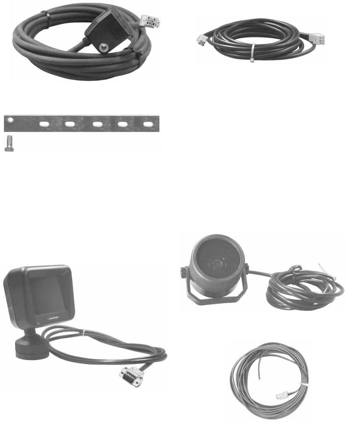
Componentry Fig. 1
Wheel sensors (2x) |
Wheel sensor extension cord (2x) |
Display |
Loudspeaker |
- 23 -
 Loading...