


AUTORADIO
T2/F3 ASB EU
T-Line 2 CR |
T-Line 2 CD |
Funline 3 |
Dresden C31 |
Konstanz CD31 |
Düsseldorf C51 |
7 641 115 510 |
7 641 155 310 |
7 641 205 310 |
Dublin C31 |
San Remo CD31 |
Bologna C51 |
7 641 120 510 |
7 641 160 310 |
7 641 210 310 |
Boston C31 |
Santa Cruz CD31 |
Kansas DJ51 |
7 641 125 510 |
7 641 166 310 |
|
Freiburg C31 |
Essen CD31 |
7 641 405 319 |
7 641 140 510 |
7 641 171 310 |
Maryland DJ51 |
Canberra C31 |
Lausanne CD31 |
7 641 410 319 |
7 641 145 510 |
7 641 172 310 |
Hawaii DJ51 |
Cleveland DJ31 |
Alicante CD31 |
7 641 420 319 |
7 641 173 310 |
|
|
7 641 116 319 |
|
|
Madison DJ31 |
|
|
7 641 121 319 |
|
|
Las Vegas |
|
München CD51 |
7 641 141 319 |
|
7 641 255 310 |
San Diego |
|
Modena CD51 |
7 641 146 319 |
|
7 641 260 310 |
8 622 402 980 BN 03/01
• Serviceanleitung / • Service Manual
Abgleich und Programmierungen nur mit Softwaretool (ComServer) möglich All alignment and programming steps can only be carried out with the ComServer
software tool.
CLASS 1
LASER PRODUCT
UNSICHTBARE LASERSTRAHLUNG NICHT DEM STRAHL AUSSETZEN
LASER CLASS 3B
D VORSICHT!
Die CD-Geräte beinhalten eine Laserkomponente! Im Servicefall bitte nachfolgende Hinweise beachten:
-Das Gerät arbeitet mit einem unsichtbaren Laserstrahl.
-Bei geöffnetem Gerät tritt im Bereich des Plattenfaches
Laserstrahlung aus.
-Nicht in den Strahl blicken.
-Unbeteiligte Personen vom Arbeitsplatz fernhalten.
-Der Betrachtungsabstand darf 13 cm nicht unterschreiten.
-Kann dies nicht eingehalten werden, muß eine geeignete Laserschutzbrille getragen werden.
GB CAUTION!
The CD units are equipped with a laser component! For servicing make sure to observe the following instructions:
-The unit operates with invisible laser beams.
-When the cover is removed, invisible laser beams are emitted near the disc compartment.
-Avoid direct eye contact with these beams.
-Keep unauthorised persons away from the workbench.
-The viewing distance should not be less than 13 cm.
-If this distance cannot be kept, use suitable laser safety goggles.

D Inhaltsverzeichnis |
|
Inhaltsverzeichnis, Ausstattung des Arbeitsplatzes |
...................... 2 |
Meßpunkte .................................................................................... |
3 |
Main Feature list Funline3 ............................................................ |
4 |
Main Feature list T-Line2 .............................................................. |
5 |
Belegung des Anschlußkastens ................................................... |
6 |
Vorbereitende Arbeiten, Abgleichhinweise |
|
Reparaturhinweise, Demomode ................................................... |
7 |
Antennenanpassung ..................................................................... |
8 |
MAUS - Software + Hardware .............................................. |
9 + 10 |
F3/T2_ASB_EU CFG Datei installieren ............................... |
11 - 13 |
Comport setzen .......................................................................... |
14 |
Konfigurationsdatei laden ................................................... |
15 + 16 |
EEPROM programmieren ................................................... |
17 + 18 |
DAA programmieren ........................................................... |
19 + 20 |
Programmierung der FM - ZF - Ablage ....................................... |
21 |
FM Feldstärke programmieren ................................................... |
22 |
AM Feldstärke programmieren ................................................... |
23 |
Programmieren der Stereo Schaltschwelle ................................. |
24 |
FM Suchlaufstop - Programmierungen ....................................... |
25 |
AM/MW Suchlaufstop - Programmierungen ................................ |
26 |
AM/LW Suchlaufstop - Programmierungen ................................. |
27 |
Programmieren der RDS Schaltschwelle .................................... |
28 |
Dolby - Abgleich .......................................................................... |
29 |
Ausstattung des Arbeitsplatzes:
1.PC ab Pentium II oder höher
2."ComServer" Software + Dongletreiber + Lies mich Datei 8 627 003 058 (1 CD-Rom Win95/98 + WinNT)
3.Interface (MAUS-Bus / K-Bus auf RS232 Schnittstelle)
8 627 004 057
4.Steckernetzteil für Interface (12V / 500mA) 8 627 004 061
5.Dongle (Hardware Sicherheitssystem in Verbindung mit dem MAUS-Bus) 8 627 004 059 (nur für dekodierberechtigte
Servicestellen)
6.Anschlußkabel MAUS-Bus (Lautsprecher-ISO Stecker mit 2 Kontaktnadeln) 8 627 004 042
7.Verbindungskabel RS232 (PC zum Interface) 8 627 004 015
8.Konfigurationsdateien (MAUS-Bus-Kommandos + Serviceanleitung MAUS) für die F3/T2 Geräte mit der Bestellnummer
8 627 003 072 (1 Diskette MS DOS 31/2 Zoll)
9.Netzgerät 15 V regelbar, 10 A (Betriebsspannung service 13,5 V)
10.Meßsender (z.B. Meguro, Leader, Kenwood)
11.Hochohmiges Voltmeter Ri > 10 MΩ
12.Outputmeter; Frequenzzähler; NF-Millivoltmeter; Stereocoder
13. Oszilloskop: |
- Empfindlichkeit: 5 mV bis 50 Volt/cm. |
-Bandbreite: Gleichspannung bis 50 MHz.
14.Tastköpfe 10:1 und 1:1
15.Schraubendreher / Abgleichstifte (keramisch)
16.Lötstation
Die Ausstattungselemente von Punkt 2 bis 8 können über unser zentrales Ersatzteillager bestellt werden.
Voraussetzung dafür ist, dass ein entsprechender Serviceund Softwarevertrag mit Blaupunkt abgeschlossen wurde.
Haben Sie dazu Fragen, wenden Sie sich bitte an Ihren nationalen Servicemanager.
Adresse: Blaupunkt-Werke GmbH
Zentrales Ersatzteillager
Robert-Bosch-Straße 200
D-31139 Hildesheim
GB Table of Contents |
|
Table of Contents, Work place equipment |
.................................... 2 |
Measuremend points .................................................................... |
3 |
Main Feature list Funline3 ............................................................ |
4 |
Main Feature list T-Line2 .............................................................. |
5 |
Pinning of terminal box ................................................................. |
6 |
Preparatory steps, Notes on alignment ......................................... |
6 |
Repair notes, demo mode ............................................................ |
7 |
Antenna matching ......................................................................... |
8 |
MAUS software + hardware .......................................................... |
9 |
Installation of F3/T2_ASB_EU CFG file .............................. |
11 - 13 |
Setting the comport ..................................................................... |
14 |
Loading the configuration file .............................................. |
15 + 16 |
Programming the EEPROM ............................................... |
17 + 18 |
Programming DAA .............................................................. |
19 + 20 |
Programming of FM IF offset ...................................................... |
21 |
Programming of the FM fieldstrengh ........................................... |
22 |
Programming of the AM fieldstrengh ........................................... |
23 |
Programming of the stereo threshold .......................................... |
24 |
FM search stop programming ..................................................... |
25 |
AM/MW search stop programming ............................................. |
26 |
AM/LW search stop programming .............................................. |
27 |
Programming of the RDS threshold ............................................ |
28 |
Dolby alignment .......................................................................... |
29 |
Work place equipment:
1.Pentium II or higher
2."ComServer" software + dongle driver + read-me files 8 627 003 058 (1 CD-Rom Win 95/98 + WinNT)
3.Interface (MAUS bus / K-bus to RS232 interface)
8 627 004 057
4.Power adapter for interface (12V / 500mA) 8 627 004 061
5.Dongle (hardware security system in connection with the MAUS bus) 8 627 004 059 (for authorised decoding agents only)
6.MAUS bus cable (ISO speaker connector with 2 pins)
8 627 004 042
7.Extension cable RS232 (PC to interface) 8 627 004 015
8.Configuration files (MAUS bus commands + service manual
MAUS) for the F3/T2 units with order number 8 627 003 072 (1 MS DOS 31/2 inch diskette).
9.Power supply unit 15 volts adjustable, 10 A (Supply voltage service 13.5 V)
10.Signal generator (Meguro, Leader, Kenwood)
11.High impedance voltmeter Ri > 10 MΩ
12.Output meter; frequency counter; AF millivoltmeter; stereo encoder
13.Oscilloscope: - inp. sensitivity: 5 mV to 50 volts per division - bandwidth: d.c. to 50 MHz
14.Probes 10:1 and 1:1
15.Screwdriver / adjusting pins (ceramic)
16.Soldering station
The items listed under 2 - 8 are available from our Central Spare Parts Warehouse.
For this it is necessary that you have entered into a corresponding service and software agreement with Blaupunkt. If you should have any questions on this topic, then please get in touch with your national service manager.
Adress: Blaupunkt-Werke GmbH
Zentrales Ersatzteillager
Robert-Bosch-Straße 200
D-31139 Hildesheim
- 2 -

Meßpunkte / Measurement points
MP158
(FS)
Hauptplatte
Main board
PL 4604 D05
Chip
- 3 -
Main Feature list Funline3
|
Düsseldorf |
Bologna |
München |
Modena |
Wiesbaden |
Sevilla |
|
Kansas |
Maryland |
|
|
|
|
Features |
|
Hawaii |
|
|
|
|
|
|
|
|
|
|
|
FM-Preset |
2x6 |
2x6 |
2x6 |
2x6 |
2x6 |
2x6 |
MW-Preset |
|
1x6 |
|
1x6 |
|
1x6 |
LW-Preset |
|
1x6 |
|
1x6 |
|
1x6 |
FMT |
1x6 |
1x6 |
1x6 |
1x6 |
1x6 |
1x6 |
HICUT |
Ö |
Ö |
Ö |
Ö |
Ö |
Ö |
lo/dx |
3/3 |
3/3 |
3/3 |
3/3 |
3/3 |
3/3 |
Mechanism CC |
TN708 |
TN708 |
|
|
|
|
Dolby B |
Ö |
Ö |
|
|
|
|
Metal |
Ö |
Ö |
|
|
|
|
S-CPS |
Ö |
Ö |
|
|
|
|
Repeat |
Ö |
Ö |
|
|
|
|
Radio Monitor |
Ö |
Ö |
|
|
|
|
Mechanism CD |
|
|
BP4 |
BP4 |
BP4 |
BP4 |
Track Mix |
|
|
Ö |
Ö |
Ö |
Ö |
Track Repeat |
|
|
Ö |
Ö |
Ö |
Ö |
Track Scan |
|
|
Ö |
Ö |
Ö |
Ö |
X-Bass |
3 steps |
3 steps |
3 steps |
3 steps |
|
|
Loudness ON/OFF |
|
|
|
|
6 steps |
6 steps |
Preamp |
4 x 3V |
4 x 3V |
4 x 3V |
4 x 3V |
4 x 3V |
4 x 3V |
Display |
negative |
negative |
negative |
negative |
negative |
negative |
Flip Panel |
Ö |
Ö |
Ö |
Ö |
Ö |
Ö |
DMS |
ASCI |
ASCI |
ASCI |
ASCI |
ASCI |
ASCI |
Code for IDC A09 |
Ö |
Ö |
Ö |
Ö |
Ö |
Ö |
Dimmer |
Ö |
Ö |
Ö |
Ö |
Ö |
Ö |
AUX IN |
Ö |
Ö |
Ö |
Ö |
Ö |
Ö |
Tel IN |
Ö |
Ö |
Ö |
Ö |
|
|
Radio Mute |
Ö |
Ö |
Ö |
Ö |
Ö |
Ö |
IR RC08/RC10 |
optional |
optional |
optional |
optional |
optional |
optional |
Peak Level Meter |
Ö |
Ö |
Ö |
Ö |
Ö |
Ö |
Clock |
Ö |
Ö |
Ö |
Ö |
Ö |
Ö |
Release Panel |
Ö |
Ö |
Ö |
Ö |
Ö |
Ö |
RP Case |
Ö |
Ö |
Ö |
Ö |
Ö |
Ö |
|
|
|
|
|
|
|
- 4 -

- 5 -
|
Cleveland |
Dublin |
Freiburg |
Canberra |
Essen |
Lausanne |
Alicante |
Konstanz |
San Remo |
Santa Cruz |
|
Dresden |
Boston |
Las Vegas |
San Diego |
|
|
|
|
|
|
|
|
Madison |
|
|
|
|
|
|
|
|
Features |
|
|
|
|
|
|
|
|
|
|
|
|
|
|
|
|
|
|
|
|
|
FM-Preset |
2x5 |
2x5 |
2x5 |
2x5 |
2x5 |
2x5 |
2x5 |
2x5 |
2x5 |
2x5 |
MW-Preset |
|
1x5 |
|
1x5 |
1x5 |
1x5 |
1x5 |
|
1x5 |
1x5 |
LW-Preset |
|
1x5 |
|
1x5 |
1x5 |
1x5 |
1x5 |
|
1x5 |
1x5 |
FMT |
1x5 |
1x5 |
1x5 |
1x5 |
1x5 |
1x5 |
1x5 |
1x5 |
1x5 |
1x5 |
HICUT |
Ö |
Ö |
Ö |
Ö |
Ö |
Ö |
Ö |
Ö |
Ö |
Ö |
lo/dx |
3/3 |
3/3 |
3/3 |
3/3 |
3/3 |
3/3 |
3/3 |
3/3 |
3/3 |
3/3 |
Mechanism CC |
ADC 1400 |
ADC 1400 |
TN708 |
TN708 |
|
|
|
|
|
|
Dolby |
B |
B |
B |
B |
|
|
|
|
|
|
Metal |
Ö |
Ö |
Ö |
Ö |
|
|
|
|
|
|
S-CPS |
Ö |
Ö |
Ö |
Ö |
|
|
|
|
|
|
Repeat |
Ö |
Ö |
Ö |
Ö |
|
|
|
|
|
|
Mechanism CD |
|
|
|
|
BP4 |
BP4 |
BP4 |
BP4 |
BP4 |
BP4 |
Track Mix |
|
|
|
|
Ö |
Ö |
Ö |
Ö |
Ö |
Ö |
Track Repeat |
|
|
|
|
Ö |
Ö |
Ö |
Ö |
Ö |
Ö |
Track Scan |
|
|
|
|
Ö |
Ö |
Ö |
Ö |
Ö |
Ö |
X-Bass |
3 steps |
3 steps |
3 steps |
3 steps |
3 steps |
3 steps |
3 steps |
3 steps |
3 steps |
3 steps |
Preamp |
|
|
4 x 3V |
4 x 3V |
|
|
|
4 x 3V |
4 x 3V |
4 x 3V |
DMS |
ASCI |
ASCI |
ASCI |
ASCI |
ASCI |
ASCI |
ASCI |
ASCI |
ASCI |
ASCI |
Code for IDC A09 |
Ö |
Ö |
Ö |
Ö |
|
|
|
Ö |
Ö |
Ö |
AUX IN |
Ö |
Ö |
Ö |
Ö |
Ö |
Ö |
Ö |
Ö |
Ö |
Ö |
Tel IN |
|
|
Ö |
Ö |
|
|
|
Ö |
Ö |
Ö |
Radio Mute |
Ö |
Ö |
Ö |
Ö |
Ö |
Ö |
Ö |
Ö |
Ö |
Ö |
IR Remote Control RC08/RC10 |
optional |
optional |
optional |
optional |
optional |
optional |
optional |
optional |
optional |
optional |
Peak Level Meter |
Ö |
Ö |
Ö |
Ö |
Ö |
Ö |
Ö |
Ö |
Ö |
Ö |
Clock manual |
Ö |
Ö |
Ö |
Ö |
Ö |
Ö |
Ö |
Ö |
Ö |
Ö |
Facia colour |
black |
black |
titanium |
titanium |
black |
black |
titanium |
titan/chrom |
titan/chrom |
titan/chrom |
Release Panel |
Ö |
Ö |
Ö |
Ö |
Ö |
Ö |
Ö |
Ö |
Ö |
Ö |
RP Case |
Ö |
Ö |
Ö |
Ö |
Ö |
Ö |
Ö |
Ö |
Ö |
Ö |
|
|
|
|
|
|
|
|
|
|
|
Line2-T list Feature Main
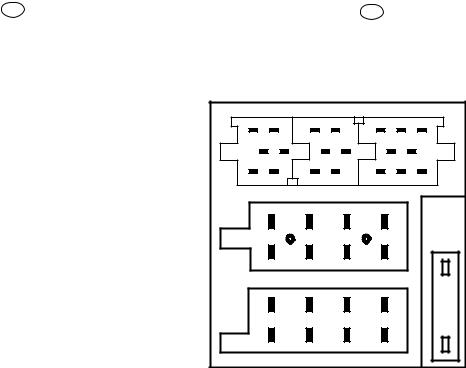
D Belegung des Anschlußkästchens |
GB Pin assignment of quickfit connector |
C
B
A
C-1 |
C-2 |
|
C-3 |
|||
1 |
4 |
7 |
10 |
13 |
16 |
19 |
3 |
6 |
9 |
12 |
|
15 |
18 |
2 |
5 |
8 |
11 |
14 |
17 |
20 |
1 |
|
3 |
5 |
7 |
|
|
|
a |
|
b |
|
|
|
2 |
|
4 |
6 |
8 |
|
|
1 |
|
3 |
5 |
7 |
|
|
2 |
|
4 |
6 |
8 |
|
|
|
|
|
|
|
|
A |
|
|
|
|
|
|
B |
|
|
||
|
|
1 |
|
|
|
NC |
|
|
|
1 |
|
Speaker Out (RR +) 4Ω |
|
||||
|
|
|
|
|
|
|
|
|
|
|
|
|
|
|
|
||
|
|
|
|
|
|
Radio mute |
|
|
2 |
|
Speaker Out (RR -) 4Ω |
|
|||||
|
|
2 |
|
<2volts = active; open = not active |
|
|
|
|
|
|
|
|
|||||
|
|
3 |
|
|
|
NC |
|
|
|
3 |
|
Speaker Out (RF +) 4Ω |
|
||||
|
|
|
|
|
|
|
|
|
|
|
|
|
|
||||
|
|
4 |
|
Permanent plus (KL 30); 10 A |
|
4 |
|
Speaker Out (RF-) 4Ω |
|
||||||||
|
|
|
|
|
|
|
|
|
|
|
|
|
|
|
|
||
* Nur Funline 3 Geräte |
5 |
|
|
Automatic antenna |
|
|
5 |
|
Speaker Out (LF +) 4Ω |
|
|||||||
|
|
|
|
|
|
|
|
|
|
|
|
|
|
|
|
||
*6 |
Illumination, active high (3 - 12 volts) |
|
6 |
|
Speaker Out (LF-) 4Ω |
|
|||||||||||
* only Funline 3 units |
|
|
|
||||||||||||||
|
|
|
|
|
|
|
|
|
|
|
|
|
|
|
|
||
|
|
|
|
|
Ignition plus, (KL 15) |
|
|
|
|
Speaker Out (LR +) 4Ω |
|
||||||
|
|
7 |
|
<2.5volts = Ign.off; >7volts = Ign.on |
|
7 |
|
|
|
|
|
|
|||||
|
|
8 |
|
|
|
Ground |
|
|
|
8 |
|
Speaker Out (LR-) 4Ω |
|
||||
|
|
|
|
|
|
|
|
|
|
|
|
|
|
|
|||
|
|
a |
|
MAUS-BUS-OUT |
(TXD) |
<0.5volts = logic 0; >3.5volts = logic 1 |
|
|
|||||||||
|
|
|
|
|
|
|
|
|
|
|
|
|
|
|
|||
|
|
b |
|
MAUS-BUS-IN |
(RXD) |
<1volt = logic 0; >3.5volts = logic 1 |
|
|
|||||||||
|
|
|
|
|
|
|
|
|
|
|
|
|
|
||||
|
|
|
|
|
(+) Nur Funline 3 Geräte / (+) only Funline 3 units |
|
|
||||||||||
|
|
|
|
|
|
|
|
|
|
|
|
|
|
|
|
|
|
|
|
|
|
|
|
|
|
|
C |
|
|
|
|
|
|
|
|
|
C1 |
|
|
|
|
|
|
|
C2 |
|
|
|
|
|
|
|
C3 |
*1 |
Line out, 3V/10kΩ (LR) |
|
7 |
|
Tel.-/Navi. AF In 10V/560Ω |
|
13 |
|
CD-Changer ASCI IN / +TMC-Out |
||||||||
|
|
|
|
|
|
|
|
( Not Sevilla + Wiesbaden) |
|
|
|
<1volt = logic 0; >3.5volts = logic 1 |
|||||
*2 |
Line out, 3V/10kΩ (RR) |
|
8 |
|
Tel.-/Navi. AF In 10V/560Ω |
|
14 |
|
CD-Changer ASCI OUT / +TMC-Out |
||||||||
|
|
|
|
|
|
|
|
( Not Sevilla + Wiesbaden) |
|
|
|
<0.5volt = logic 0; >3.5volts = logic 1 |
|||||
*3 |
Line out ground |
|
|
9 |
|
|
|
NC |
|
15 |
|
CDC permanent plus (bloc A / pin 4) |
|||||
|
|
|
|
|
|
|
|
|
|
|
|||||||
*4 |
Line out out, 3V/10kΩ (LF) |
|
10 |
|
|
+12 V switched |
|
16 |
|
+12 V switched |
|||||||
|
|
|
|
|
|
|
|
|
|
|
|||||||
*5 |
Line out out, 3V/10kΩ (RF) |
|
|
|
|
Remote control PWM |
|
17 |
|
CD-Changer I2C-Bus Masse / Gnd. |
|||||||
|
|
|
|
|
|
11 |
|
<1volt = logic 0; >3.5volts = logic 1 |
|
|
|
|
|||||
*6 |
+12 V switched |
|
|
12 |
|
Remote control Ground |
|
18 |
|
Aux Ground |
|||||||
|
|
|
|
|
|
|
|
|
|
|
|
|
|
|
|
|
|
|
|
|
|
|
|
|
|
|
|
|
|
|
|
19 |
|
Aux input 2V/6kΩ (L) |
|
|
|
|
|
|
|
|
|
|
|
|
|
|
|
|
|
|
|
|
|
|
|
|
|
|
|
|
|
|
|
|
|
20 |
|
Aux input 2V/6kΩ (R) |
|
|
|
|
|
|
|
|
|
|
|
|
|
|
|
|
|
|
|
* Nicht Cleveland, Boston, Dresden, Dub lin, Madison, Essen, |
* Not Cleveland, Boston, Dresden, Dub lin, Madison, Essen, |
Lausanne und Alicante. |
Lausanne und Alicante. |
IG für A/Pin5; C1/Pin6; C2/Pin10 + C3/P = 300 mA. |
IG for A/Pin5; C1/Pin6; C2/Pin10 + C3/P = 300 mA. |
|
|
- 6 -

D Abgleichhinweise
Der Abgleich erfolgt nur noch elektronisch über den PC (ComServer ). Es dürfen keine Filter abgeglichen werden. Nach dem Tausch eines Filters, mss der Abgleich über den PC erfolgen.
Wellenbereich:
FM = 87,5 MHz - 108,0 MHz
(100 kHz automatische Suchlaufschritte)
(50 kHz manuelle Suchlaufschritte)
MW = 531 kHz - 1602 kHz
(9 kHz automatische Suchlaufschritte) (9 kHz manuelle Suchlaufschritte)
LW = 153 kHz - 279 kHz
(9 kHz automatische Suchlaufschritte) (1 kHz manuelle Suchlaufschritte)
Vorbereitende Arbeiten
Bevor Sie den elektrischen Abgleich durchführen, müssen Sie folgende Vorbereitungen treffen:
Höhen - Einstellung ........................................................................ |
0 |
Bass - Einstellung .......................................................................... |
0 |
Fader - Einstellung (nicht Lübeck/Luxembourg) ............................ |
0 |
Balance - Einstellung ...................................................................... |
0 |
Loudness - Einstellung (DSC Menü) ............................. |
1 oder OFF |
X-Bass - Einstellung (DSC Menü) ............................................. |
OFF |
Lautsprecheranschluß
Der Lautsprecherausgang muß mit 4 Ω abgeschlossen sein.
Demomode
Demomode aktivieren
1.Schalten Sie das Autoradio aus.
2.Betätigen Sie die Tasten 1 + 6 (Funline 3); 1 + 5 (T-Line 2) gleichzeitig und halten Sie die Tasten gedrückt.
3.Schalten Sie das Gerät ein und halten Sie die Tasten noch für ca. 1 Sekunde gedrückt.
Nach diesem Schritt erscheint im Display nach "BLAUPUNKT" der Schriftzug "Demo".
Demomode deaktivieren
Sie verlassen den Servicemode durch Ausschalten des Autoradios. Wiederholen Sie bitte den Schritt 1-3 um den Demomode zu verlassen.
Software Version Hauptprozessor und Kappenprozessor
Testmode aktivieren
1.Schalten Sie das Autoradio aus.
2.Betätigen Sie die Tasten 1 + 2 gleichzeitig und halten Sie die Tasten gedrückt.
3.Schalten Sie das Gerät ein und halten Sie die Tasten noch für ca. 1 Sekunde gedrückt.
Das Autoradiodisplay zeigt 8 Zeichen an.
Die 4 linken Zeichen zeigen den Softwarestand des Hauptprozessors an und die 4 rechten Zeichen zeigen den Softwarestand des Kappenprozessors an.
Testmode deaktivieren
Sie verlassen den Service Mode durch Ausschalten des Autoradios.
GB Notes on alignment
The alignment is always done electronically using a PC (ComServer). Do not align any filters. If a filter has been replaced, align the unit with the PC.
Waveband:
FM = 87.5 MHz - 108.0 MHz
(100 kHz automatic search steps)
(50 kHz manual search steps)
MW = 531 kHz - 1602 kHz
(9 kHz automatic search steps) (9 kHz manual search steps)
LW = 153 kHz - 279 kHz
(9 kHz automatic search steps) (1 kHz manual search steps)
Preparatory steps
Observe the following preparations before performing the electrical alignment:
Treble adjustment .......................................................................... |
0 |
Bass adjustment ............................................................................ |
0 |
Fader adjustment (not Lübeck/Luxembourg) ................................. |
0 |
Balance adjustment ........................................................................ |
0 |
Loudness adjustment (DSC menu) ................................... |
1 or OFF |
X-Bass adjustment (DSC menu) ............................................... |
OFF |
Loudspeaker connections |
|
The loudspeaker output must be terminated with 4 Ω. |
|
Demo mode
Activating the Demo mode
1.Switch the unit off.
2.Press the push-buttons 1 + 6 (Funline 3); 1 + 5 (T-Line 2) simultaneously and hold them depressed.
3.Switch the unit back on and hold on to the buttons for approximately one more second.
Following this step, the display will show the wording “BLAUPUNKT” followed by “Demo”.
Deactivating the Demo mode
You can quit the service mode by switching the radio off. Wiederholen Sie bitte den Schritt 1-3 um den Demomode zu verlassen.
Software version main processor and panel prozessor
Activating the test mode
1.Switch the unit off.
2.Press the push-buttons 1 + 2 simultaneously and hold them depressed.
3.Switch the unit back on and hold on to the buttons for approximately one more second.
The car radio display shows 8 characters.
The left 4 characters indicate the software version of the main processor, the right 4 characters indicate the software version of the panel processor.
To exit the test mode
You can quit the service mode by switching the radio off.
- 7 -
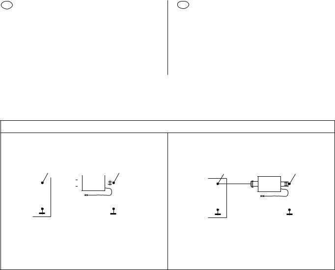
D Antennenanpassung
E' - Beispiele bei FM und AM
E' = Bezugspunkt (unbelasteter Ausgang der Anpaßschaltung/ künstliche Antenne) in dBμV.
Y = Meßsendereinstellung in dBμV oder μV.
V = Meßsenderbedämpfung durch die Eingangsimpedanz der Anpaßschaltung (Leistungsanpassung).
X = Dämpfung der künstlichen Antenne in dB.
GB Antenna matching
E' - examples for FM and AM
E' = reference point (output of matching device/dummy antenna without load) in dBμV.
Y = adjustment of the signal generator in dBμV or μV.
V = attenuation of the signal generator output due to the load applied by the matching device (power adaptation).
X = attenuation of the dummy antenna in dB.
Meßsender / signal generator: Meguro, Leader, Kenwood
Künstliche Antenne AM:
Dummy antenna AM:
|
Y |
|
|
|
|
|
E' (40 dBμV) |
||
|
|
V = 6 dB |
|
|
|
|
|
|
|
|
|
|
|
|
X = 14 dB |
|
|
|
|
|
|
|
|
|
|
|
|||
|
|
|
|
|
|
X = 20 dB |
|
|
|
|
|
|
|
|
|
|
|
||
|
|
|
|
|
|
|
|
|
|
Meguro
Leader
Kenwood
|
Y = V + X + E' |
(X =14 dB) |
Y = 6 dB + 14 dB + 40 dBμV |
|
Y = 60 dBμV = 1 mV |
(X =20 dB) |
Y = 6 dB + 20 dB + 40 dBμV |
|
Y = 66 dBμV = 2 mV |
Künstliche Antenne FM:
Dummy antenna FM:
Y |
E’ (40 dBμV) |
V = 6 dB
Meguro
Leader
Kenwood
Y = V + E'
Y = 6 dB + 40 dBμV
Y = 46 dBμV = 200 μV
dBUmrechnungstabelle |
dB Conversion table |
dB |
0 |
1 |
2 |
3 |
4 |
5 |
6 |
7 |
8 |
9 |
|
|
|
|
|
|
|
|
|
|
|
|
|
0 |
1 |
1,12 |
1,26 |
1,41 |
1,59 |
1,78 |
2,00 |
2,24 |
2,51 |
2,82 |
|
10 |
3,16 |
3,55 |
3,98 |
4,47 |
5,01 |
5,62 |
6,31 |
7,08 |
7,94 |
8,91 |
|
20 |
10,0 |
11,2 |
12,6 |
14,1 |
15,9 |
17,8 |
20,0 |
22,4 |
25,1 |
28,2 |
|
30 |
31,6 |
35,5 |
39,8 |
44,7 |
50,1 |
56,2 |
63,1 |
70,8 |
79,4 |
89,1 |
|
40 |
100 |
112 |
126 |
141 |
159 |
178 |
200 |
224 |
251 |
282 |
|
50 |
316 |
355 |
398 |
447 |
501 |
562 |
631 |
708 |
794 |
891 |
|
60 |
1 000 |
1 122 |
1 259 |
1 413 |
1 585 |
1 778 |
1 995 |
2 239 |
2 512 |
2 818 |
|
70 |
3 162 |
3 548 |
3 981 |
4 469 |
5 012 |
5 623 |
6 310 |
7 080 |
7 943 |
8 912 |
|
|
|
|
|
|
Faktoren / Factors |
|
|
|
|
|
|
|
|
|
|
|
|
|
|
|
|
|
|
- 8 -

DMAUS - Software + Hardware
(MAUS = Multifunktionsbus für
Abgleich Und Start Up)
PC - Vorausetzungen
IBM - Kompatibler Computer: Ab Pentium 2 oder höher
Betriebssystem: Windows 95/98 + WinNT4
MAUS Ausstattung
a) "ComServer" (Software + Dongletreiber + Lies mich Datei + Serviceanleitungen MAUS)
8 627 003 058 (CD-Rom)
b)Konfigurationsdateien (MAUS-Bus-Kommandos + Serviceanleitung MAUS) für die F3/T2 Geräte mit der Bestellnummer
8 627 003 072 (1 Diskette MS DOS 31/2 Zoll)
c)Interface (MAUS-Bus / K-Bus auf RS232 Schnittstelle)
8 627 004 057
d)Steckernetzteil für Interface (12V / 500 mA)
8 627 004 061
e)Dongle (Hardware Sicherheitssystem in Verbindung mit dem
MAUS-Bus)
8 627 004 059 (nur für decodierberechtigte Servicestellen)
Achtung: Bitte stecken Sie den "DONGLE" nur bei ausgeschalteten PC auf die LPT Drucker schnittstelle.
f)Maus Bus Kabel (Lautsprecher - ISO Stecker mit 2 Kontakt nadeln)
8 627 004 042
g)Verlängerungskabel RS232 (PC zum Interface)
8 627 004 015
GB MAUS software + hardware
(MAUS = multi-function bus for alignment and start-up)
Required PC equipment
IBM-compatible computer: |
Pentium 2 or higher |
Operating system: |
Windows 95/98 + WinNT4 |
MAUS equipment
a) "ComServer" (software + dongle driver + read me file + service manuals MAUS)
8 627 003 058 (CD-Rom)
b)Configuration files (MAUS bus commands + service manual MAUS) for the F3/T2 units with order number
8 627 003 072 (1 MS DOS 31/2 inch diskette).
c)Interface (MAUS-bus / K-bus to RS232 interface)
8 627 004 057
d)Power adapter (12 V / 500 mA)
8 627 004 061
e)Dongle (hardware security system in connection with the MAUS-bus)
8 627 004 059 (for authorised decoding agents only)
Warning: Please plug the "DONGLE" into the printer port only if the PC is switched "OFF".
f)MAUS bus cable
(speaker - ISO connector with 2 contact pins)
8 627 004 042
g)Extension cable RS232 (PC to interface)
8 627 004 015
- 9 -
 Loading...