


 Loading...
P10S WS
Motherboard

E11165
First Edition
January 2016
Copyright© 2016 ASUSTeK COMPUTER INC. All Rights Reserved.
No part of this manual, including the products and software described in it, may be reproduced, transmitted, transcribed, stored in a retrieval system, or translated into any language in any form or by any means, except documentation kept by the purchaser for backup purposes, without the express written permission of ASUSTeK COMPUTER INC. (“ASUS”).
Product warranty or service will not be extended if: (1) the product is repaired, modified or altered, unless such repair, modification of alteration is authorized in writing by ASUS; or (2) the serial number of the product is defaced or missing.
ASUS PROVIDES THIS MANUAL “AS IS” WITHOUT WARRANTY OF ANY KIND, EITHER EXPRESS OR IMPLIED, INCLUDING BUT NOT LIMITED TO THE IMPLIED WARRANTIES OR CONDITIONS OF MERCHANTABILITY OR FITNESS FOR A PARTICULAR PURPOSE. IN NO EVENT SHALL ASUS, ITS DIRECTORS, OFFICERS, EMPLOYEES OR AGENTS BE LIABLE FOR ANY INDIRECT, SPECIAL, INCIDENTAL, OR CONSEQUENTIAL DAMAGES (INCLUDING DAMAGES FOR LOSS OF PROFITS, LOSS OF BUSINESS, LOSS OF USE OR DATA, INTERRUPTION OF BUSINESS AND THE LIKE), EVEN IF ASUS HAS BEEN ADVISED OF THE POSSIBILITY OF SUCH DAMAGES ARISING FROM ANY DEFECT OR ERROR IN THIS MANUAL OR PRODUCT.
SPECIFICATIONS AND INFORMATION CONTAINED IN THIS MANUAL ARE FURNISHED FOR INFORMATIONAL USE ONLY, AND ARE SUBJECT TO CHANGE AT ANY TIME WITHOUT NOTICE, AND SHOULD NOT BE CONSTRUED AS A COMMITMENT BY ASUS. ASUS ASSUMES NO RESPONSIBILITY OR LIABILITY FOR ANY ERRORS OR INACCURACIES THAT MAY APPEAR IN THIS MANUAL, INCLUDING THE PRODUCTS AND SOFTWARE DESCRIBED IN IT.
Products and corporate names appearing in this manual may or may not be registered trademarks or copyrights of their respective companies, and are used only for identification or explanation and to the owners’ benefit, without intent to infringe.
Offer to Provide Source Code of Certain Software
This product contains copyrighted software that is licensed under the General Public License (“GPL”), under the Lesser General Public License Version (“LGPL”) and/or other Free Open Source Software Licenses. Such software in this product is distributed without any warranty to the extent permitted by the applicable law. Copies of these licenses are included in this product.
Where the applicable license entitles you to the source code of such software and/or other additional data, you may obtain it for a period of three years after our last shipment of the product, either
(1)for free by downloading it from https://www.asus.com/support/
or
(2)for the cost of reproduction and shipment, which is dependent on the preferred carrier and the location where you want to have it shipped to, by sending a request to:
ASUSTeK Computer Inc.
Legal Compliance Dept.
15 Li Te Rd.,
Beitou, Taipei 112
Taiwan
In your request please provide the name, model number and version, as stated in the About Box of the product for which you wish to obtain the corresponding source code and your contact details so that we can coordinate the terms and cost of shipment with you.
The source code will be distributed WITHOUT ANY WARRANTY and licensed under the same license as the corresponding binary/object code.
This offer is valid to anyone in receipt of this information.
ASUSTeK is eager to duly provide complete source code as required under various Free Open Source Software licenses. If however you encounter any problems in obtaining the full corresponding source code we would be much obliged if you give us a notification to the email address gpl@asus.com, stating the product and describing the problem (please DO NOT send large attachments such as source code archives, etc. to this email address).
ii

Contents
Safety information..................................................................................................... |
vii |
About this guide........................................................................................................ |
viii |
P10S WS specifications summary............................................................................. |
x |
Package contents..................................................................................................... |
xiii |
Installation tools and components.......................................................................... |
xiv |
Chapter 1: |
Product Introduction |
|
|
1.1 |
Special features.......................................................................................... |
1-1 |
|
|
1.1.1 |
Product highlights........................................................................ |
1-1 |
|
1.1.2 |
ASUS-exclusive workstation features.......................................... |
1-2 |
|
1.1.3 |
Other special features.................................................................. |
1-2 |
1.2 |
Motherboard overview............................................................................... |
1-3 |
|
|
1.2.1 |
Before you proceed..................................................................... |
1-3 |
|
1.2.2 |
Motherboard layout...................................................................... |
1-4 |
|
1.2.3 |
Central Processing Unit (CPU).................................................... |
1-6 |
|
1.2.4 |
System memory........................................................................... |
1-7 |
|
1.2.5 |
Expansion slots............................................................................ |
1-9 |
|
1.2.6 |
Onboard buttons and switches.................................................. |
1-12 |
|
1.2.7 |
Jumpers..................................................................................... |
1-16 |
|
1.2.8 |
Onboard LEDs........................................................................... |
1-17 |
|
1.2.9 |
Internal connectors.................................................................... |
1-23 |
Chapter 2: |
Basic Installation |
|
|
2.1 |
Building your PC system........................................................................... |
2-1 |
|
|
2.1.1 |
Motherboard installation.............................................................. |
2-1 |
|
2.1.2 |
CPU installation........................................................................... |
2-3 |
|
2.1.3 |
CPU heatsink and fan assembly installation................................ |
2-5 |
|
2.1.4 |
DIMM installation......................................................................... |
2-7 |
|
2.1.5 |
ATX power connection................................................................. |
2-8 |
|
2.1.6 |
SATA device connection.............................................................. |
2-9 |
|
2.1.7 |
Front I/O connector.................................................................... |
2-10 |
|
2.1.8 |
Expansion card installation........................................................ |
2-11 |
2.2 |
BIOS update utility.................................................................................... |
2-12 |
|
2.3 |
Motherboard rear and audio connections.............................................. |
2-14 |
|
|
2.3.1 |
Rear I/O connection................................................................... |
2-14 |
|
2.3.2 |
Audio I/O connections................................................................ |
2-16 |
2.4 |
Starting up for the first time.................................................................... |
2-18 |
|
2.5 |
Turning off the computer......................................................................... |
2-19 |
|
iii

Contents
Chapter 3: |
BIOS Setup |
|
|
3.1 |
Knowing BIOS............................................................................................. |
3-1 |
|
3.2 |
BIOS setup program................................................................................... |
3-2 |
|
|
3.2.1 |
EZ Mode...................................................................................... |
3-3 |
|
3.2.2 |
Advanced Mode........................................................................... |
3-4 |
|
3.2.3 |
QFan Control............................................................................... |
3-7 |
3.3 |
My Favorites................................................................................................ |
3-9 |
|
3.4 |
Main menu................................................................................................. |
3-11 |
|
3.5 |
Ai Tweaker menu...................................................................................... |
3-13 |
|
3.6 |
Advanced menu........................................................................................ |
3-23 |
|
|
3.6.1 |
CPU Configuration..................................................................... |
3-24 |
|
3.6.2 |
Platform Misc Configuration....................................................... |
3-26 |
|
3.6.3 |
System Agent (SA) Configuration.............................................. |
3-28 |
|
3.6.4 |
PCH Configuration..................................................................... |
3-29 |
|
3.6.5 |
PCH Storage Configuration....................................................... |
3-30 |
|
3.6.6 |
USB Configuration..................................................................... |
3-32 |
|
3.6.7 |
Network Stack Configuration..................................................... |
3-33 |
|
3.6.8 |
Onboard Devices Configuration................................................. |
3-33 |
|
3.6.9 |
APM Configuration..................................................................... |
3-36 |
|
3.6.10 |
HDD/SSD SMART Information.................................................. |
3-37 |
3.7 |
Monitor menu............................................................................................ |
3-38 |
|
3.8 |
Boot menu................................................................................................. |
3-42 |
|
3.9 |
Tool menu.................................................................................................. |
3-47 |
|
|
3.9.1 |
ASUS EZ Flash 3 Utility............................................................. |
3-47 |
|
3.9.2 |
ASUS Overclocking Profile........................................................ |
3-48 |
|
3.9.3 |
ASUS SPD Information.............................................................. |
3-49 |
3.10 |
Exit menu................................................................................................... |
3-50 |
|
3.11 |
Updating BIOS.......................................................................................... |
3-51 |
|
|
3.11.1 |
EZ Update.................................................................................. |
3-51 |
|
3.11.2 |
ASUS EZ Flash 3....................................................................... |
3-52 |
|
3.11.3 |
ASUS CrashFree BIOS 3.......................................................... |
3-54 |
iv

Contents
Chapter 4: |
Software Support |
|
|
4.1 |
Installing an operating system.................................................................. |
4-1 |
|
|
4.1.1 |
Windows ® 7 and USB 3.0 driver for 100 Series ........................... |
4-1 |
4.2 |
Support DVD information........................................................................... |
4-8 |
|
|
4.2.1 |
Running the support DVD ............................................................ |
4-8 |
|
4.2.2 |
Obtaining the software manuals .................................................. |
4-9 |
4.3 |
Software information................................................................................ |
4-10 |
|
4.4 |
AI Suite 3 |
................................................................................................... |
4-10 |
|
4.4.1 ............................................................................... |
Ai Charger+ |
4-13 |
|
4.4.2 ........................................................................... |
USB 3.1 Boost |
4-14 |
|
4.4.3 .................................................................................. |
EZ Update |
4-15 |
|
4.4.4 .................................................................... |
System Information |
4-17 |
|
4.4.5 ........................................................................... |
Mobo Connect |
4-19 |
|
4.4.6 ................................................................ |
USB BIOS Flashback |
4-20 |
|
4.4.7 ............................................................................... |
Push Notice |
4-22 |
4.5 |
Audio configurations................................................................................ |
4-25 |
|
Chapter 5: |
RAID Support |
|
|
5.1 |
RAID configurations................................................................................... |
5-1 |
|
|
5.1.1 |
RAID definitions........................................................................... |
5-1 |
|
5.1.2 |
Installing Serial ATA hard disks................................................... |
5-2 |
|
5.1.3 |
Setting the RAID item in BIOS..................................................... |
5-2 |
5.1.4Intel® Rapid Storage Technology enterprise
|
SATA Option ROM Utility............................................................. |
5-3 |
5.1.5 |
Creating a RAID set..................................................................... |
5-4 |
5.1.6 |
Deleting a RAID set..................................................................... |
5-6 |
5.1.7 |
Resetting disks to Non-RAID....................................................... |
5-7 |
5.1.8Exiting the Intel® Rapid Storage Technology enterprise
|
|
SATA Option ROM utility............................................................. |
5-8 |
|
5.1.9 |
Rebuilding the RAID.................................................................... |
5-8 |
|
5.1.10 |
Setting the Boot array in the BIOS Setup Utility........................ |
5-10 |
5.2 |
Intel® Rapid Storage Technology enterprise (Windows)...................... |
5-11 |
|
|
5.2.1 |
Creating a RAID set................................................................... |
5-12 |
|
5.2.2 |
Changing a Volume Type.......................................................... |
5-14 |
|
5.2.3 |
Deleting a volume...................................................................... |
5-15 |
|
5.2.4 |
Preferences............................................................................... |
5-16 |
v

Chapter 6: |
Multi GPU Support |
|
|
6.1 |
AMD® CrossFireX™ technology................................................................ |
6-1 |
|
|
6.1.1 |
Requirements.............................................................................. |
6-1 |
|
6.1.2 |
Before you begin.......................................................................... |
6-1 |
|
6.1.3 |
Installing two CrossFireX™ graphics cards................................. |
6-2 |
|
6.1.4 |
Installing the device drivers......................................................... |
6-4 |
|
6.1.5 |
Enabling the AMD® CrossFireX™ technology............................. |
6-4 |
Appendix |
|
|
|
P10S WS block diagram.......................................................................................... |
A-1 |
||
Notices |
..................................................................................................................... |
|
A-2 |
ASUS contact information...................................................................................... |
A-6 |
||
vi

Safety information
Electrical safety
•To prevent electrical shock hazard, disconnect the power cable from the electrical outlet before relocating the system.
•When adding or removing devices to or from the system, ensure that the power cables for the devices are unplugged before the signal cables are connected. If possible, disconnect all power cables from the existing system before you add a device.
•Before connecting or removing signal cables from the motherboard, ensure that all power cables are unplugged.
•Seek professional assistance before using an adapter or extension cord. These devices could interrupt the grounding circuit.
•Ensure that your power supply is set to the correct voltage in your area. If you are not sure about the voltage of the electrical outlet you are using, contact your local power company.
•If the power supply is broken, do not try to fix it by yourself. Contact a qualified service technician or your retailer.
Operation safety
•Before installing the motherboard and adding devices on it, carefully read all the manuals that came with the package.
•Before using the product, ensure all cables are correctly connected and the power cables are not damaged. If you detect any damage, contact your dealer immediately.
•To avoid short circuits, keep paper clips, screws, and staples away from connectors, slots, sockets and circuitry.
•Avoid dust, humidity, and temperature extremes. Do not place the product in any area where it may become wet.
•Place the product on a stable surface.
•If you encounter technical problems with the product, contact a qualified service technician or your retailer.
vii

About this guide
This user guide contains the information you need when installing and configuring the motherboard.
How this guide is organized
This guide contains the following parts:
1.Chapter 1: Product Introduction
This chapter describes the features of the motherboard and the new technology it supports. It includes description of the switches, jumpers, and connectors on the motherboard.
2.Chapter 2: Basic Installation
This chapter lists the hardware setup procedures that you have to perform when installing system components.
3.Chapter 3: BIOS Setup
This chapter tells how to change system settings through the BIOS Setup menus. Detailed descriptions of the BIOS parameters are also provided.
4.Chapter 4: Software Support
This chapter describes the contents of the support DVD that comes with the motherboard package and the software.
5.Chapter 5: RAID Support
This chapter describes the RAID configurations.
6.Chapter 6: Multi GPU Support
This chapter describes how to install and configure multiple AMD® CrossFire™ graphics cards.
Where to find more information
Refer to the following sources for additional information and for product and software updates.
1.ASUS website
The ASUS website (www.asus.com) provides updated information on ASUS hardware and software products.
2.Optional documentation
Your product package may include optional documentation, such as warranty flyers, that may have been added by your dealer. These documents are not part of the standard package.
viii

Conventions used in this guide
To ensure that you perform certain tasks properly, take note of the following symbols used throughout this manual.
DANGER/WARNING: Information to prevent injury to yourself when trying to complete a task.
CAUTION: Information to prevent damage to the components when trying to complete a task.
IMPORTANT: Instructions that you MUST follow to complete a task.
NOTE: Tips and additional information to help you complete a task.
Typography
Bold text |
Indicates a menu or an item to select. |
Italics |
Used to emphasize a word or a phrase. |
<Key> |
Keys enclosed in the less-than and greater-than sign |
|
means that you must press the enclosed key. |
|
Example: <Enter> means that you must press the Enter or |
|
Return key. |
<Key1> + <Key2> + <Key3> |
If you must press two or more keys simultaneously, the key |
|
names are linked with a plus sign (+). |
ix

P10S WS specifications summary
|
LGA1151 socket for Intel® Xeon® E3-1200 v5 Processor Family |
|
|
LGA1151 socket for Intel® Core™ i7/i5/i3 processors |
|
|
LGA1151 socket for Intel® Pentium™ processors |
|
CPU |
LGA1151 socket for Intel® Celeron™ processors |
|
|
Support Intel® 14nm CPU |
|
|
Support Intel® Turbo Boost Technology |
|
|
* Refer to www.asus.com for Intel® CPU support list |
|
Chipset |
Intel® C236 Chipset |
|
|
4 x DIMM, Max 64GB, DDR4 2133 MHz, ECC/ non-ECC UDIMM |
|
Memory |
Dual channel architecture |
|
|
* Refer to www.asus.com for the Memory QVL(Qualified Vendors List). |
|
|
|
|
|
PCIEX16_1: PCI-E x16 slot, x16/ x8 Gen3 Link |
|
Expansion slots |
PCIEX16_2: PCI-E x16 slot, x8 Gen3 Link, switched from PCIEX16_1 |
|
PCIEX16_3: PCI-E x16 slot, x4 Gen3 Link, from PCH |
||
|
||
|
PCIEX16_4: PCI-E x16 slot, x4 Gen3 Link, from PCH |
|
|
|
|
|
Integrated Graphics Processor x 1 |
|
|
Multi-VGA output support: DVI-D/HDMI/DisplayPort/VGA |
|
|
- Supports DVI-D with Max resolution 1920 x 1200@60 Hz |
|
|
- Supports HDMI with Max resolution 4096 x 2160@60/24 Hz |
|
VGA |
- Supports DisplayPort with Max resolution 4096 x 2304@60Hz |
|
|
- Supports VGA with Max resolution 1920 x 1200@60 Hz |
|
|
- Supports Intel® HD Graphics, InTru™ 3D, Quick Sync Video, Clear |
|
|
Video HD Technology, Insider™ |
|
|
- Maximum shared memory of 512MB |
|
|
|
|
Multi-GPU support |
Support AMD® Quad-GPU CrossFireXTM Technology |
|
|
Intel® C236 Chipset: |
|
Storage |
8 x SATA 6Gb/s ports or 6 x SATA 6Gb/s with 2 x M.2 (SATA 6Gb/s & |
|
PCIe Gen3 x1 link, NGFF 22110/2280/2260/2242) |
||
|
||
|
- Intel® RSTe (Windows & Linux, support software RAID 0, 1, 10 & 5) |
|
LAN |
2 x Intel I210 GbE LAN |
|
(Support teaming function) |
||
|
||
|
|
|
|
Intel® C236 Chipset |
|
|
- 4 x USB 2.0 ports (4 ports Type A at mid-board) |
|
USB |
- 6 x USB 3.0 ports (2 ports Type A at front panel, 4 ports Type A at |
|
back panel) |
||
|
||
|
- 2 x USB 3.1 ports (1 port at TypeA and 1 port at Type C at back |
|
|
panel) |
|
|
|
|
|
(continued on the next page) |
x
P10S WS specifications summary
Audio |
Realtek® ALC1150 8-channel high definition audio CODEC |
|
- Separate layer for left and right track, ensuring both sound deliver |
|
equal quality |
|
- Top notch audio sensation delivers according to the audio |
|
configuration |
|
- Audio shielding ensures precise analog/digital separation and |
|
greatly reduced multi-lateral interference |
|
- Audio Amplifier to enhance the highest quality sound for |
|
headphone and speakers |
|
- Premium Japan-made audio capacitors provides warm, natural, |
|
and immersive sound with exceptional clarity and fidelity |
|
- High quality 112dB SNR stereo playback output (Line-out@back) |
|
& 104dB SNR recording input (Line-in) support |
|
- Absolute Pitch 192khz/24bit true BD lossless sound |
|
- BD audio layer content protection |
|
- DTS Studio Sound |
|
- DTS Connect |
|
- Supports jack-detection, multi-streaming, front panel jack- |
|
retasking (MIC) |
|
- Optical S/PDIF out port at back I/O |
|
|
ASUS Exclusive |
ASUS DIGI + Power Control: 3+2+1 Phase Power Design |
Features |
- CPU Power: Digital 3-phase power design |
|
|
|
- iGPU Power: Digital 2-phase power design |
|
- DRAM Power: Digital 1-phase power design |
|
ASUS EPU: |
|
- EPU |
|
ASUS Quiet Thermal Solution: |
|
- ASUS Fanless Design: Heat-sink solution |
|
ASUS EZ DIY: |
|
- ASUS CrashFree BIOS 3 |
|
- ASUS EZ Flash Utility |
|
|
Rear Panel I/O Ports |
- 2 x USB 3.1 ports (1 port at TypeA, 1 port at Type C) |
|
- 1 x Optical S/PDIF Out |
|
- 1 x HDMI |
|
- 1 x DisplayPort |
|
- 4 x USB 3.0 ports |
|
- 2 x RJ-45 ports |
|
- 1 x DVI-D |
|
- 1 x VGA |
|
- 8-channel Audio I/O ports (6 x Audio jacks) |
|
(continued on the next page) |
xi

P10S WS specifications summary
Internal I/O Connectors |
- 2 x USB 2.0 connectors support additional 4 USB ports (9-pin) |
|
|
|
- 1 x USB 3.0 connectors support additional 2 USB ports (19-pin) |
|
|
- 8 x SATA 6.0Gb/s ports |
|
|
- 2 x M.2 Socket |
|
|
- 4 x Chassis Fan connectors (4-pin) for both 3-pin(DC mode) and |
|
|
4-pin(PWM mode) coolers control |
|
|
- 1 x CPU OPT Fan connector (4-pin) |
|
|
- 1 x CPU fan with PWM control (4-pin) |
|
|
- 1 x Front panel audio connector (AAFP) |
|
|
- 1 x S/PDIF out header |
|
|
- 1 x TPM connector |
|
|
- 1 x 24-pin EATX Power connector |
|
|
- 1 x 8-pin EATX12V Power connector |
|
|
- 1 x 6-pin EATX12V_1 Power connector |
|
|
- 1 x System Panel(Q-Connector) |
|
|
- 1 x MemOK! Button |
|
|
- 1 x Clear CMOS button |
|
|
- 1 x USB BIOS Flashback button |
|
|
- 1 x DRCT(Direct Key) connector |
|
|
- 1 x EPU switch |
|
|
- 1 x Power-on button |
|
|
- 1 x COM port header |
|
|
|
BIOS features |
16 MB Flash ROM, EFI AMI BIOS, PnP, DMI3.0, WfM2.0, SM BIOS |
|
|
|
3.0, ACPI 5.0a, ASUS EZ Flash Utility, ASUS CrashFree BIOS 3 |
|
|
|
Manageability |
WfM 2.0, DMI 3.0, WOL by PME, WOR by PME, PXE |
|
|
|
|
OS |
- Windows Server 2008 R2 SP1 |
|
|
|
- Windows Server 2012 R2 |
|
|
- Windows 7 SP1 |
|
|
- Windows 8.1 |
|
|
- Windows 10 |
|
|
- RedHat® Enterprise Linux |
|
|
- SUSE Linux Enterprise Server |
|
|
- CentOS |
|
|
- Scientific Linux |
|
|
- Ubuntu 14 |
|
|
- Fedora |
|
|
|
WHQL |
- Windows 8.1/64 bit |
|
|
|
- Windows 10/64 bit (TBD) |
|
|
- Windows 2012 R2 64 bit |
|
|
- Windows 7 SP1 |
|
|
|
Form Factor |
ATX Form Factor, 12” x 9.6” (305mm x 244mm) |
|
|
|
|
Specifications are subject to change without notice.
xii
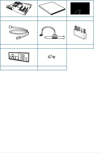
Package contents
Check your motherboard package for the following items:
|
Manual |
|
|
User |
|
ASUS P10S WS motherboard |
User manual |
Support DVD |
8 x Serial ATA 6.0 Gb/s cables |
1 x COM port bracket |
1 x Q-connector |
1 x ASUS Q-Shield |
2 x M.2 Screw package |
|
xiii
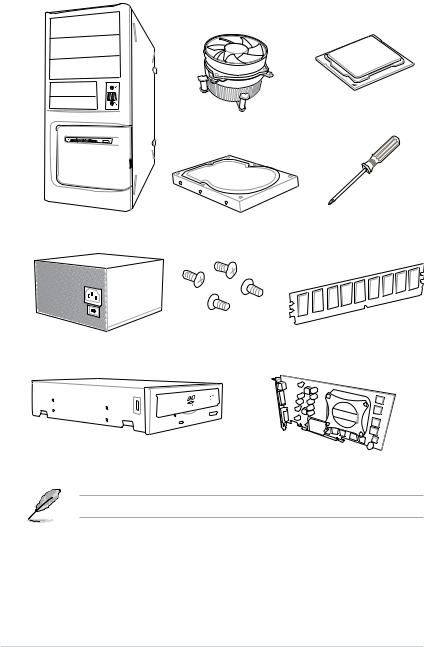
Installation tools and components
Intel® LGA1151 CPU
Intel® LGA1151 compatible CPU Fan
SATA hard disk drive |
Phillips (cross) screwdriver |
PC chassis |
|
1 bag of screws |
DIMM |
|
Power supply unit
SATA optical disc drive (optional)
Graphics card
The tools and components in the table above are not included in the motherboard package.
xiv

Product Introduction |
1 |
1.1Special features
1.1.1Product highlights
LGA1151 socket for the 6th Generation Intel® Core™ i7/Intel® Core™ i5/Intel® Core™ i3, Pentium® and Celeron® processors
This motherboard supports 6th generation Intel® Core™ i7/Intel® Core™ i5/Intel® Core™ i3, Pentium® , and Celeron® processors in the LGA1151 package. It provides great graphics and system performance with its GPU, dual-channel DDR4 memory slots and PCI Express 2.0/3.0 expansion slots.
Intel® C236 Express Chipset
Intel® C236 Express Chipset is a single chipset that supports the LGA1151 socket for the 6th generation Intel® Core™ i7/Intel® Core™ i5/Intel® Core™ i3, Pentium® , and Celeron® processors. It utilizes the serial point-to-point links, which increases bandwidth and enhances the system’s performance. It natively supports up to ten USB 3.0 ports, up to eight SATA 6 Gb/s ports, and up to M.2 Gen 3 X4 support for faster data retrieval.
PCI Express® 3.0
PCI Express® 3.0 (PCIe 3.0) is the PCI Express bus standard that provides twice the performance and speed of PCIe 2.0. It provides an optimal graphics performance, unprecedented data speed and seamless transition with its complete backward compatibility to PCIe 1.0/2.0 devices.
Dual-Channel DDR4 2133 MHz Support
The motherboard supports the dual-channel DDR4 memory that features data transfer rates of DDR4 2133 MHz to boost the system’s performance, and to meet the higher bandwidth requirements of 3D graphics, multimedia and Internet applications.
Dual PCIe 3.0 X1 M.2 Support
With a 1 x PCI Express 3.0/2.0 bandwidth, dual M.2 sockets provide the flexibility to enable top-flight performance (RAID 0) or data redundancy (RAID 1) via SATA mode. It is a perfect choice for the operating system or application drive.
Complete USB 3.1 integration
This motherboard has the latest USB 3.1 connectivity built in for the very fastest USB data transfers — that’s up to 10 Gb/s, or twice as fast as USB 3.0. The next-generation standard is completely backward-compatible with your existing USB devices, and you’ll be all set for USB 3.1’s breakneck speeds.
Chapter 1
ASUS P10S WS |
1-1 |

1 Chapter
1.1.2ASUS-exclusive workstation features
PCI Express 3.0 for Quad-GPU CrossFireX™ Support
The motherboard provides PCI Express x16 slots for Quad-GPU AMD CrossFireX™ graphics cards, giving you with ample graphics power to easily run even the most demanding computer games for enhanced entertainment.
ProCool Connector
ProCool eliminates the hollow areas associated with traditional power connectors, ensuring an exceptionally close and secure connection with this motherboard. This design is much stronger, and provides better heat dissipation, allowing cooler operating temperatures.
Built-in dual Intel® Ethernet
For more reliable networking, this motherboard features the latest server class built-in dual Intel® Ethernet. This leads to lower CPU utilization and temperatures, achieving outstanding performance, and providing better support for diverse operating systems.
1.1.3Other special features
DTS Connect
To get the most out of your audio entertainment across all formats and quality levels, DTS Connect combines two enabling technologies, DTS Neo:PC™ upmixes stereo sources (CDs, MP3s, WMAs, internet radio) into as many as 7.1 channels of incredible surround sound. Consumers can connect their PC to a home theater system. DTS Interactive is capable of performing mult-channel encoding of DTS bitstreams on personal computers, and sending encoded bitstreams out of a digital audio connection (such as S/PDIF or HDMI) designed to deliver audio to an external decoder.
ErP Ready
The motherboard is European Union’s Energy-related Products (ErP) ready, and ErP requires products to meet certain energy efficiency requirement in regards to energy consumptions. This is in line with ASUS vision of creating environment-friendly and energyefficient products through product design and innovation to reduce carbon footprint of the product and thus mitigate environmental impacts.
1-2 |
Chapter 1: Product Introduction |

1.2Motherboard overview
1.2.1Before you proceed
Take note of the following precautions before you install motherboard components or change any motherboard settings.
• Unplug the power cord from the wall socket before touching any component.
•Before handling components, use a grounded wrist strap or touch a safely grounded object or a metal object, such as the power supply case, to avoid damaging them due to static electricity.
•Hold components by the edges to avoid touching the ICs on them.
•Whenever you uninstall any component, place it on a grounded antistatic pad or in the bag that came with the component.
•Before you install or remove any component, ensure that the ATX power supply is switched off or the power cord is detached from the power supply. Failure to do so may cause severe damage to the motherboard, peripherals, or components.
Chapter 1
ASUS P10S WS |
1-3 |

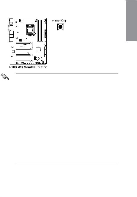
1.2.2Motherboard layout
1 Chapter
Refer to 1.2.9 Internal connectors and 2.3.1 Rear I/O connection for more information about rear panel connectors and internal connectors.
1-4 |
Chapter 1: Product Introduction |

Layout contents
Connectors/Jumpers/Buttons and switches/Slots |
Page |
|
1. |
ATX power connectors (24-pin EATXPWR; 8-pin EATX12V; 6-pin |
1-29 |
|
EATX12V_1) |
|
2. |
LGA1151 CPU socket |
1-6 |
3. |
CPU, CPU optional, and chassis fan connectors (4-pin CPU_FAN; 4-pin |
1-28 |
|
CPU_OPT; 4-pin CHA_FAN1-4) |
|
4. |
DDR4 DIMM slots |
1-7 |
5. |
MemOK! button |
1-13 |
6. |
USB 3.0 connectors (20-1 pin USB3_12) |
1-27 |
7. |
Clear CMOS button (CLR_CMOS) |
1-15 |
8. |
Intel® C236 Serial ATA 6 Gb/s connectors (7-pin SATA6G_1-8) |
1-23 |
9. |
EPU switch |
1-14 |
10. |
DirectKey connector (2-pin DRCT) |
1-31 |
11. |
Chassis Fan control setting (3 pin CHAFAN_SEL) |
1-16 |
12. |
Chassis Intrusion connector (4-1 pin CHASSIS) |
1-25 |
13. |
System panel connector (20-5 pin PANEL) |
1-30 |
14. |
BIOS Flashback button |
2-12 |
15. |
Reset button |
1-12 |
16. |
Power button |
1-12 |
17. |
M.2 Socket 3 |
1-32 |
18. |
USB 2.0 connectors (10-1 USB1112; USB910) |
1-26 |
19. |
TPM connector (14-1 pin TPM) |
1-25 |
20. |
Q-Code LEDs |
1-19 |
21. |
Serial port connector (10-1 pin COM1) |
1-31 |
22. |
Front panel audio connector (10-1 pin AAFP) |
1-24 |
23. |
Digital audio connector (4-1 pin SPDIF_OUT) |
1-24 |
|
|
|
Chapter 1
ASUS P10S WS |
1-5 |
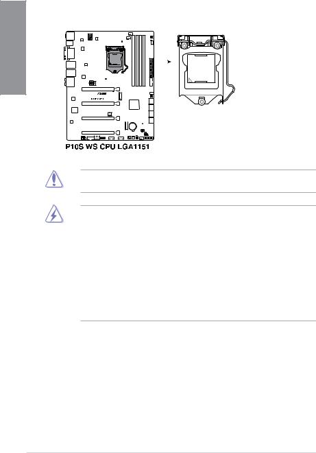
1.2.3Central Processing Unit (CPU)
The motherboard comes with a surface mount LGA1151 socket designed for the 6th Generation Intel® Core™ i7 / Intel® Core™ i5 / Intel® Core™ i3, Pentium®, Celeron®, and Intel® Xeon® E3-1200 v5 processors.
1 Chapter
Ensure that you install the correct CPU designed for LGA1151 socket only. DO NOT install a CPU designed for other sockets on the LGA1151 socket.
•Ensure that all power cables are unplugged before installing the CPU.
•Upon purchase of the motherboard, ensure that the PnP cap is on the socket and the socket contacts are not bent. Contact your retailer immediately if the PnP cap is missing, or if you see any damage to the PnP cap/socket contacts/motherboard components. ASUS will shoulder the cost of repair only if the damage is shipment/ transit-related.
•Keep the cap after installing the motherboard. ASUS will process Return Merchandise
Authorization (RMA) requests only if the motherboard comes with the cap on the LGA1151 socket.
•The product warranty does not cover damage to the socket contacts resulting from incorrect CPU installation/removal, or misplacement/loss/incorrect removal of the PnP cap.
1-6 |
Chapter 1: Product Introduction |
1.2.4System memory
The motherboard comes with four DDR 4 (Double Data Rate 4) Dual Inline Memory Modules (DIMM) slots.
A DDR4 module is notched differently from a DDR, DDR2 or DDR3 module. DO NOT install a DDR, DDR2 or DDR3 memory module to the DDR4 slot.
Recommended memory configurations
Chapter 1
ASUS P10S WS |
1-7 |
1 Chapter
Memory configurations
You may install 2 GB, 4 GB, 8 GB and 16 GB unbuffered and ECC and non ECC DDR4
DIMMs into the DIMM sockets.
• You may install varying memory sizes in Channel A and Channel B. The system maps the total size of the lower-sized channel for the dual-channel configuration. Any excess memory from the higher-sized channel is then mapped for single-channel operation.
•According to Intel® CPU spec, DIMM voltage below 1.65 V is recommended to protect the CPU.
•Due to the memory address limitation on 32-bit Windows® OS, when you install 4GB or more memory on the motherboard, the actual usable memory for the OS can be about 3GB or less. For effective use of memory, we recommend that you do any of the following:
a)Use a maximum of 3GB system memory if you are using a 32-bit Windows® OS.
b)Install a 64-bit Windows® OS when you want to install 4 GB or more on the motherboard.
c)For more details, refer to the Microsoft® support site at http://support.microsoft. com/kb/929605/en-us.
•This motherboard does not support DIMMs made up of 512 Mb (64 MB) chips or less
(Memory chip capacity counts in Megabit, 8 Megabit/Mb = 1 Megabyte/MB).
•For system stability, use a more efficient memory cooling system to support a full memory load (4 DIMMs).
•Always install the DIMMS with the same CAS Latency. For an optimum compatibility, we recommend that you install memory modules of the same version or data code (D/C) from the same vendor. Check with the vendor to get the correct memory modules.
•Visit the ASUS website for the latest QVL.
1-8 |
Chapter 1: Product Introduction |
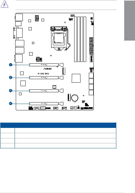
1.2.5Expansion slots
Unplug the power cord before adding or removing expansion cards. Failure to do so may cause you physical injury and damage motherboard components.
Chapter 1
Slot No. Slot Description
1PCIe 3.0/2.0 x16_1 slot
2PCIe 3.0/2.0 x16_2 slot
3PCIe 3.0/2.0 x16_3 slot
4PCIe 3.0/2.0 x16_4 slot
ASUS P10S WS |
1-9 |
1 Chapter
|
PCI Express 3.0 operating mode |
|
Slot |
|
|
|
|
|
No. |
Single VGA |
CrossFireX |
|
||
|
|
|
1 |
x16 |
x8 |
(single VGA |
|
|
|
recommended) |
|
|
|
|
2 |
- |
x8 |
|
|
|
3 |
- |
- |
|
||
|
|
|
4 |
- |
- |
|
|
|
• We recommend that you provide sufficient power when running CrossFireX™ mode.
•Connect a chassis fan to the motherboard connector labeled CHA_FAN1-4 when using multiple graphics cards for better thermal environment.
•We recommend you connect an EATX12V cable when running CrossFireX™.
1-10 |
Chapter 1: Product Introduction |

IRQ assignments for this motherboard
|
A |
B |
C |
D |
E |
F |
G |
H |
|
|
|
|
|||||||||
|
|
|
|
|
|
|
|
|
|
|
PCIe x16_1 |
shared |
- |
- |
- |
- |
- |
- |
- |
|
1 |
|
|
|
|
|
|
|
|
|
|
|
PCIe x16_2 |
shared |
- |
- |
- |
- |
- |
- |
- |
|
|
|
Chapter |
|||||||||
|
|
|
|
|
|
|
|
|
|
|
PCIe x16_3 |
shared |
- |
- |
- |
- |
- |
- |
- |
|
|
|
|
|||||||||
|
|
|
|
|
|
|
|
|
|
|
PCIe x16_4 |
shared |
- |
- |
- |
- |
- |
- |
- |
|
|
|
|
|
|
|
|
|
|
|
|
|
SMBUS Controller |
shared |
- |
- |
- |
- |
- |
- |
- |
|
|
|
|
|
|
|
|
|
|
|
|
|
Intel SATA Controller |
- |
- |
- |
- |
- |
- |
- |
shared |
|
|
|
|
|
|
|
|
|
|
|
|
|
Intel LAN1(I210) |
shared |
- |
- |
- |
- |
- |
- |
- |
|
|
|
||||||||||
|
|
|
|
|
|
|
|
|
|
|
Intel LAN2(I210) |
- |
- |
shared |
- |
- |
- |
- |
- |
|
|
|
|
|
|
|
|
|
|
|
|
|
Intel xHCI |
shared |
- |
- |
- |
- |
- |
- |
- |
|
|
|
|
|
|
|
|
|
|
|
|
|
HD Audio |
shared |
- |
- |
- |
- |
- |
- |
- |
|
|
|
|
|
|
|
|
|
|
|
|
|
ASMedia 1142_1 |
shared |
- |
|
- |
- |
- |
- |
- |
|
|
ASUS P10S WS |
1-11 |
|
1.2.6 |
|
|
|
|
|
|
|
|
|
Onboard buttons and switches |
||||||||||||||||||
|
Onboard buttons and switches allow you to fine-tune performance when working on a bare or |
||||||||||||||||||||||||||||
|
open-case system. This is ideal for overclockers and gamers who continually change settings |
||||||||||||||||||||||||||||
Chapter |
to enhance system performance. |
||||||||||||||||||||||||||||
|
up the system. The button also lights up when the system is plugged to a power source |
||||||||||||||||||||||||||||
|
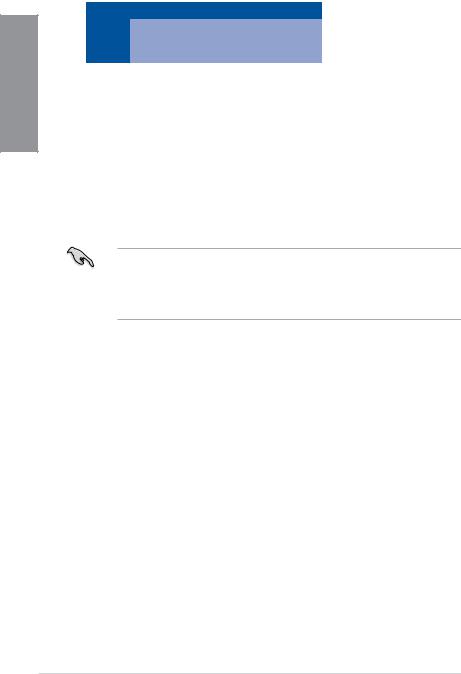
1. |
Power-on button |
|||||||||||||||||||||||||||
|
|
The motherboard comes with a power-on button that allows you to power up or wake |
|||||||||||||||||||||||||||
1 |
|
indicating that you should shut down the system and unplug the power cable before |
|||||||||||||||||||||||||||
|
removing or installing any motherboard component. |
||||||||||||||||||||||||||||
|
|
||||||||||||||||||||||||||||
|
|
|
|
|
|
|
|
|
|
|
|
|
|
|
|
|
|
|
|
|
|
|
|
|
|
|
|
|
|
|
|
|
|
|
|
|
|
|
|
|
|
|
|
|
|
|
|
|
|
|
|
|
|
|
|
|
|
|
|
|
|
|
|
|
|
|
|
|
|
|
|
|
|
|
|
|
|
|
|
|
|
|
|
|
|
|
|
|
|
|
|
|
|
|
|
|
|
|
|
|
|
|
|
|
|
|
|
|
|
|
|
|
|
|
|
|
|
|
|
|
|
|
|
|
|
|
|
|
|
|
|
|
|
|
|
|
|
|
|
|
|
|
|
|
|
|
|
|
|
|
|
|
|
|
|
|
|
|
|
|
|
|
|
|
|
|
|
|
|
|
|
|
|
|
|
|
|
|
|
|
|
|
|
|
|
|
|
|
|
|
|
|
|
|
|
|
|
|
|
|
|
|
|
|
|
|
|
|
|
|
|
|
|
|
|
|
|
|
|
|
|
|
|
|
|
|
|
|
|
|
|
|
|
|
|
|
|
|
|
|
|
|
|
|
|
|
|
|
|
|
|
|
|
|
|
|
|
|
|
|
|
|
|
|
|
|
|
|
|
|
|
|
|
|
|
|
|
|
|
|
|
|
|
|
|
|
|
|
|
|
|
|
|
|
|
|
|
|
|
|
|
|
|
|
|
|
|
|
|
|
|
|
|
|
|
|
|
|
|
|
|
|
|
|
|
|
|
|
|
|
|
|
|
|
|
|
|
|
|
|
|
|
|
|
|
|
|
|
|
|
|
|
|
|
|
|
|
|
|
|
|
|
|
|
|
|
|
|
|
|
|
|
|
|
|
|
|
|
|
|
|
|
|
|
|
|
|
|
|
|
|
|
|
|
|
|
|
|
|
|
|
|
|
|
|
|
|
|
|
|
|
|
|
|
|
|
|
|
|
|
|
|
|
|
|
|
|
|
|
|
|
|
|
|
|
|
|
|
|
|
|
|
|
|
|
|
|
|
|
|
|
|
|
|
|
|
|
|
|
|
|
|
|
|
|
|
|
|
|
|
|
|
|
|
|
|
|
|
|
|
|
|
|
|
|
|
|
|
|
|
|
|
|
|
|
|
|
|
|
|
|
|
|
|
|
|
|
|
|
|
|
|
|
|
|
|
|
|
|
|
|
|
|
|
|
|
|
|
|
|
|
|
|
|
|
|
|
|
|
|
|
|
|
|
|
|
|
|
|
|
|
|
|
|
|
|
|
|
|
|
|
|
|
|
|
|
|
|
|
|
|
|
|
|
|
|
|
|
|
|
|
|
|
|
|
|
|
|
|
|
|
|
|
|
|
|
|
|
|
|
|
|
|
|
|
|
|
|
|
|
|
|
|
|
|
|
|
|
|
|
|
|
|
|
|
|
|
|
|
|
|
|
|
|
|
|
|
|
|
|
|
|
|
|
|
|
|
|
|
|
|
|
|
|
|
|
|
|
|
|
|
|
|
|
|
|
|
|
|
|
|
|
|
|
|
|
|
|
|
|
|
|
|
|
|
|
|
|
|
|
|
|
|
|
|
|
|
|
|
|
|
|
|
|
|
|
|
|
|
|
|
|
|
|
|
|
|
|
|
2.Reset button
Press the reset button to reboot the system.
|
|
|
|
|
|
|
|
|
|
|
|
|
|
|
|
|
|
|
|
|
|
|
|
|
|
|
|
|
|
|
|
|
|
|
|
|
|
|
|
|
|
|
|
|
|
|
|
|
|
|
|
|
|
|
|
|
|
|
|
|
|
|
|
|
|
|
|
|
|
|
|
|
|
|
|
|
|
|
|
|
|
|
|
|
|
|
|
|
|
|
|
|
|
|
|
|
|
|
|
|
|
|
|
|
|
|
|
|
|
|
|
|
|
|
|
|
|
|
|
|
|
|
|
|
|
|
|
|
|
|
|
|
|
|
|
|
|
|
|
|
|
|
|
|
|
|
|
|
|
|
|
|
|
|
|
|
|
|
|
|
|
|
|
|
|
|
|
|
|
|
|
|
|
|
|
|
|
|
|
|
|
|
|
|
|
|
|
|
|
|
|
|
|
|
|
|
|
|
|
|
|
|
|
|
|
|
|
|
|
|
|
|
|
|
|
|
|
|
|
|
|
|
|
|
|
|
|
|
|
|
|
|
|
|
|
|
|
|
|
|
|
|
|
|
|
|
|
|
|
|
|
|
|
|
|
|
|
|
|
|
|
|
|
|
|
|
|
|
|
|
|
|
|
|
|
|
|
|
|
|
|
|
|
|
|
|
|
|
|
|
|
|
|
|
|
|
|
|
|
|
|
|
|
|
|
|
|
|
|
|
|
|
|
|
|
|
|
|
|
|
|
|
|
|
|
|
|
|
|
|
|
|
|
|
|
|
|
|
|
|
|
|
|
|
|
|
|
|
|
|
|
|
|
|
|
|
|
|
|
|
|
|
|
|
|
|
|
|
|
|
|
|
|
|
|
|
|
|
|
|
|
|
|
|
|
|
|
|
|
|
|
|
|
|
|
|
|
|
|
|
|
|
|
|
|
|
|
|
|
|
|
|
|
|
|
|
|
|
|
|
|
|
|
|
|
|
|
|
|
|
|
|
|
|
|
|
|
|
|
|
|
|
|
|
|
|
|
|
|
|
|
|
|
|
|
|
|
|
|
|
|
|
|
|
|
|
|
|
|
|
|
|
|
|
|
|
|
|
|
|
|
|
|
|
|
|
|
|
|
|
|
|
|
|
|
|
|
|
|
|
|
|
|
|
|
|
|
|
|
|
|
|
|
|
|
|
|
|
|
|
|
|
|
|
|
|
|
|
|
|
|
|
|
|
|
|
|
|
|
|
|
|
|
|
|
|
|
|
|
|
|
|
|
|
|
|
|
|
|
|
|
|
|
|
|
|
|
|
|
|
|
|
|
|
|
|
|
|
|
|
|
|
|
|
|
|
|
|
|
|
|
|
|
|
|
|
|
|
|
|
|
|
|
|
|
|
|
|
|
|
|
|
|
|
|
|
|
|
|
|
|
|
|
|
|
|
|
|
|
|
|
|
|
|
|
|
|
|
|
|
|
|
|
|
|
|
|
|
|
|
|
|
|
|
|
|
|
|
|
|
|
|
|
|
|
|
|
|
|
|
|
|
|
|
|
|
|
|
|
|
|
|
|
|
|
|
|
|
|
|
|
|
|
|
|
|
|
|
|
|
|
|
|
|
|
|
|
|
|
|
|
|
|
|
|
|
|
|
|
|
|
|
|
|
|
|
|
|
|
|
|
|
|
|
|
|
|
|
|
|
|
|
|
|
|
|
|
|
|
|
|
|
|
|
|
|
|
|
|
|
|
|
|
|
|
|
|
|
|
|
|
|
|
|
|
|
|
|
|
|
|
|
|
|
|
|
|
|
|
|
|
|
|
|
|
|
|
|
|
|
|
|
|
|
|
|
|
|
|
|
|
|
|
|
|
|
|
|
|
|
|
|
|
|
|
|
|
|
|
|
|
|
|
|
|
|
|
|
|
1-12 |
|
|
|
|
|
|
|
|
|
|
|
|
|
|
|
|
|
|
|
|
|
|
|
|
|
|
|
|
|
|
|
|
|
Chapter 1: Product Introduction |
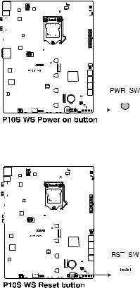
3. MemOK! button |
|
Installing DIMMs that are not compatible with the motherboard may cause system |
|
boot failure, and the DRAM_LED near the MemOK! button lights continuously. Press |
|
and hold the MemOK! button until the DRAM_LED starts blinking to begin automatic |
1 |
memory compatibility tuning for successful boot. |
|
|
Chapter |
•
•
•
•
•
•
•
•
Refer to section 1.2.8 Onboard LEDs for the exact location of the DRAM_LED.
The DRAM_LED also lights up when the DIMM is not properly installed. Turn off the system and reinstall the DIMM before using the MemOK! function.
The MemOK! button does not function under Windows® OS environment.
During the tuning process, the system loads and tests failsafe memory settings. It takes about 30 seconds for the system to test one set of failsafe settings. If the test fails, the system reboots and test the next set of failsafe settings. The blinking speed of the DRAM_LED increases, indicating different test processes.
Due to memory tuning requirement, the system automatically reboots when each timing set is tested. If the installed DIMMs still fail to boot after the whole tuning process, the DRAM_LED lights continuously. Replace the DIMMs with ones recommended in the Memory QVL (Qualified Vendors Lists) in this user manual or at www.asus.com.
If you turn off the computer and replace DIMMs during the tuning process, the system continues memory tuning after turning on the computer. To stop memory tuning, turn off the computer and unplug the power cord for about 5–10 seconds.
If your system fails to boot up due to BIOS overclocking, press the MemOK! button to boot and load the BIOS default settings. A message will appear during POST reminding you that the BIOS has been restored to its default settings.
We recommend that you download and update to the latest BIOS version from www.asus.com after using the MemOK! function.
ASUS P10S WS |
1-13 |
1 Chapter
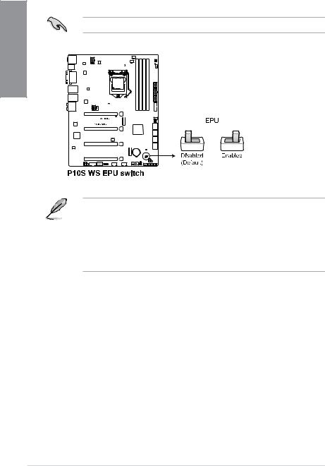
4.EPU switch
Enable this switch to automatically detect the current PC loadings and intelligently moderate the power consumption.
Enable this switch when the system is powered off.
•The EPU LED (OLED2) near the EPU switch lights up when the EPU switch is enabled. Refer to section 1.2.8 Onboard LEDs for the exact location of the EPU LED.
•If you enable this switch under Windows® OS environment, the EPU function will be activated after the next system bootup.
•You may change the EPU settings in the software application or BIOS setup program and enable the EPU function at the same time. However, the system will use the last setting you have made.
1-14 |
Chapter 1: Product Introduction |
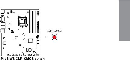
5.Clear CMOS button (CLR_CMOS)
Press this button to clear the BIOS setup information only when the systems hangs due to overclocking.
Chapter 1
|
|
|
|
|
|
|
|
|
|
|
|
|
|
|
|
|
|
|
|
|
|
|
|
|
|
|
|
|
|
|
|
|
|
|
|
|
|
|
|
|
|
|
|
|
|
|
|
|
|
|
|
|
|
|
|
|
|
|
|
|
|
|
|
|
|
|
|
|
|
|
|
|
|
|
|
|
|
|
|
|
|
|
|
|
|
|
|
|
|
|
|
|
|
|
|
|
|
|
|
|
|
|
|
|
|
|
|
|
|
|
|
|
|
|
|
|
|
|
|
|
|
|
|
|
|
|
|
|
|
|
|
|
|
|
|
|
|
|
|
|
|
|
|
|
|
|
|
|
|
|
|
|
|
|
|
|
|
|
|
|
|
|
|
|
|
|
|
|
|
|
|
|
|
|
|
|
|
|
|
|
|
|
|
|
|
|
|
|
|
|
|
|
|
|
|
|
|
|
|
|
|
|
|
|
|
|
|
|
|
|
|
|
|
|
|
|
|
|
|
|
|
|
|
|
|
|
|
|
|
|
|
|
|
|
|
|
|
|
|
|
|
|
|
|
|
|
|
|
|
|
|
|
|
|
|
|
|
|
|
|
|
|
|
|
|
|
|
|
|
|
|
|
|
|
|
|
|
|
|
|
|
|
|
|
|
|
|
|
|
|
|
|
|
|
|
|
|
|
|
|
|
|
|
|
|
|
|
|
|
|
|
|
|
|
|
|
|
|
|
|
|
|
|
|
|
|
|
|
|
|
|
|
|
|
|
|
|
|
|
|
|
|
|
|
|
|
|
|
|
|
|
|
|
|
|
|
|
|
|
|
|
|
|
|
|
|
|
|
|
|
|
|
|
|
|
|
|
|
|
|
|
|
|
|
|
|
|
|
|
|
|
|
|
|
|
|
|
|
|
|
|
|
|
|
|
|
|
ASUS P10S WS |
1-15 |
||||||||||||||||||||||

1.2.7Jumpers
1. |
Chassis Fan control setting (3-pin CHAFAN_SEL) |
|
|
This jumpers allow you to switch fan pin selection. The CHAFAN_SEL jumper is for the |
|
1Chapter |
front fans and rear fans control. Set pins 1-2 when using 3-pin fans or pins 2-3 when |
|
using 4-pin fans. |
||
|
1-16 |
Chapter 1: Product Introduction |
Loading...