


 Loading...
P10S-I
Motherboard

E13687
Revised Edition V5
December 2017
Copyright © 2017 ASUSTeK COMPUTER INC. All Rights Reserved.
No part of this manual, including the products and software described in it, may be reproduced, transmitted, transcribed, stored in a retrieval system, or translated into any language in any form or by any means, except documentation kept by the purchaser for backup purposes, without the express written permission of ASUSTeK COMPUTER INC. (“ASUS”).
Product warranty or service will not be extended if: (1) the product is repaired, modified or altered, unless such repair, modification of alteration is authorized in writing by ASUS; or (2) the serial number of the product is defaced or missing.
ASUS PROVIDES THIS MANUAL “AS IS” WITHOUT WARRANTY OF ANY KIND, EITHER EXPRESS OR IMPLIED, INCLUDING BUT NOT LIMITED TO THE IMPLIED WARRANTIES OR CONDITIONS OF MERCHANTABILITY OR FITNESS FOR A PARTICULAR PURPOSE. IN NO EVENT SHALL ASUS, ITS DIRECTORS, OFFICERS, EMPLOYEES OR AGENTS BE LIABLE FOR ANY INDIRECT, SPECIAL, INCIDENTAL, OR CONSEQUENTIAL DAMAGES (INCLUDING DAMAGES FOR LOSS OF PROFITS, LOSS OF BUSINESS, LOSS OF USE OR DATA, INTERRUPTION OF BUSINESS AND THE LIKE), EVEN IF ASUS HAS BEEN ADVISED OF THE POSSIBILITY OF SUCH DAMAGES ARISING FROM ANY DEFECT OR ERROR IN THIS MANUAL OR PRODUCT.
SPECIFICATIONS AND INFORMATION CONTAINED IN THIS MANUAL ARE FURNISHED FOR INFORMATIONAL USE ONLY, AND ARE SUBJECT TO CHANGE AT ANY TIME WITHOUT NOTICE, AND SHOULD NOT BE CONSTRUED AS A COMMITMENT BY ASUS. ASUS ASSUMES NO RESPONSIBILITY OR LIABILITY FOR ANY ERRORS OR INACCURACIES THAT MAY APPEAR IN THIS MANUAL, INCLUDING THE PRODUCTS AND SOFTWARE DESCRIBED IN IT.
Products and corporate names appearing in this manual may or may not be registered trademarks or copyrights of their respective companies, and are used only for identification or explanation and to the owners’ benefit, without intent to infringe.
ii

Contents
Notices ....................................................................................................................... |
vii |
Federal Communications Commission Statement.......................................... |
vii |
REACH ...................................................................................................... |
viii |
Australia statement notice............................................................................. |
viii |
Safety information...................................................................................................... |
ix |
Electrical safety................................................................................................ |
ix |
Operation safety.............................................................................................. |
ix |
Specifications Summary............................................................................................ |
xi |
Chapter 1: |
Product Introduction |
|
|
1.1 |
Welcome! |
..................................................................................................... |
1-2 |
1.2 |
Package contents....................................................................................... |
1-2 |
|
1.3 |
Serial number label..................................................................................... |
1-3 |
|
1.4 |
Special features.......................................................................................... |
1-3 |
|
|
1.4.1 |
Product highlights........................................................................ |
1-3 |
|
1.4.2 |
Innovative ASUS features............................................................ |
1-4 |
Chapter 2: |
Hardware Information |
|
|
2.1 |
Before you proceed.................................................................................... |
2-2 |
|
2.2 |
Motherboard overview............................................................................... |
2-3 |
|
|
2.2.1 |
Placement direction..................................................................... |
2-3 |
|
2.2.2 |
Screw holes................................................................................. |
2-3 |
|
2.2.3 |
Motherboard layout...................................................................... |
2-4 |
|
2.2.4 |
Layout contents........................................................................... |
2-5 |
2.3 |
Central Processing Unit (CPU).................................................................. |
2-7 |
|
|
2.3.1 |
Installing the CPU........................................................................ |
2-7 |
|
2.3.2 |
Installing the CPU heatsink........................................................ |
2-10 |
|
2.3.3 |
Uninstalling the CPU heatsink and fan...................................... |
2-11 |
|
2.3.4 |
Installing the CPU heatsink in rack............................................ |
2-11 |
2.4 |
System memory........................................................................................ |
2-13 |
|
|
2.4.1 |
Overview.................................................................................... |
2-13 |
|
2.4.2 |
Memory configurations.............................................................. |
2-13 |
|
2.4.3 |
Installing a DIMM on a single clip DIMM socket........................ |
2-14 |
iii

Contents
2.5 |
Expansion slots........................................................................................ |
2-15 |
|
|
2.5.1 |
Installing an expansion card ...................................................... |
2-15 |
|
2.5.2 |
Configuring an expansion card .................................................. |
2-15 |
|
2.5.3 |
Interrupt assignments ................................................................ |
2-16 |
|
2.5.4 |
PCI Express x16 slot (x16 Gen3 link) ........................................ |
2-17 |
|
2.5.5 |
Installing the Baseboard Management Card ............................. |
2-18 |
2.6 |
Onboard LEDs........................................................................................... |
2-19 |
|
2.7 |
Jumpers |
..................................................................................................... |
2-22 |
2.8 |
Connectors................................................................................................ |
2-25 |
|
|
2.8.1 ............................................................... |
Rear panel connectors |
2-25 |
|
2.8.2 ............................................................................. |
Q - Code table |
2-26 |
|
2.8.3 .................................................................... |
Internal connectors |
2-28 |
Chapter 3: |
Powering Up |
|
|
3.1 |
Starting up for the first time...................................................................... |
3-2 |
|
3.2 |
Powering off the computer........................................................................ |
3-3 |
|
|
3.2.1 |
Using the OS shut down function................................................ |
3-3 |
|
3.2.2 |
Using the dual function power switch.......................................... |
3-3 |
Chapter 4: |
BIOS Setup |
|
|
4.1 |
Managing and updating your BIOS........................................................... |
4-2 |
|
|
4.1.1 |
ASUS CrashFree BIOS 3 utility................................................... |
4-2 |
|
4.1.2 |
ASUS EzFlash Utility................................................................... |
4-3 |
|
4.1.3 |
BUPDATER utility........................................................................ |
4-4 |
4.2 |
BIOS setup program................................................................................... |
4-6 |
|
|
4.2.1 |
BIOS menu screen...................................................................... |
4-7 |
|
4.2.2 |
Menu bar...................................................................................... |
4-7 |
|
4.2.3 |
Menu items.................................................................................. |
4-8 |
|
4.2.4 |
Submenu items............................................................................ |
4-8 |
|
4.2.5 |
Navigation keys........................................................................... |
4-8 |
|
4.2.6 |
General help................................................................................ |
4-8 |
|
4.2.7 |
Configuration fields...................................................................... |
4-8 |
|
4.2.8 |
Pop-up window............................................................................ |
4-8 |
|
4.2.9 |
Scroll bar...................................................................................... |
4-8 |
4.3 |
Main menu................................................................................................... |
4-9 |
|
iv

Contents
4.4 |
Advanced menu........................................................................................ |
4-10 |
|
|
4.4.1 |
Trusted Computing.................................................................... |
4-11 |
|
4.4.2 |
Chipset Configuration................................................................ |
4-11 |
|
4.4.3 |
Platform Configuration............................................................... |
4-19 |
|
4.4.4 |
CPU Configuration..................................................................... |
4-28 |
|
4.4.5 |
SATA Configuration .................................................................. |
4-32 |
|
4.4.6 |
Network Stack Configuration .................................................... |
4-34 |
|
4.4.7 |
CSM Configuration ................................................................... |
4-35 |
|
4.4.8 |
iSCSI Configuration .................................................................. |
4-36 |
4.5 |
Security Menu........................................................................................... |
4-37 |
|
4.6 |
Boot Menu................................................................................................. |
4-39 |
|
4.7 |
Monitor Menu............................................................................................ |
4-41 |
|
4.8 |
Tool menu.................................................................................................. |
4-41 |
|
4.9 |
Save & Exit menu...................................................................................... |
4-42 |
|
4.10 |
Server Mgmt menu................................................................................... |
4-43 |
|
4.11 |
Event Logs menu...................................................................................... |
4-46 |
|
Chapter 5: |
RAID Configuration |
|
|
5.1 |
Setting up RAID.......................................................................................... |
5-2 |
|
|
5.1.1 |
RAID definitions........................................................................... |
5-2 |
|
5.1.2 |
Installing hard disk drives............................................................ |
5-3 |
|
5.1.3 |
Setting the RAID mode in BIOS................................................... |
5-3 |
|
5.1.4 |
RAID configuration utilities........................................................... |
5-3 |
5.2Intel® Rapid Storage Technology enterprise SATA Option
|
ROM Utility.................................................................................................. |
5-4 |
|
|
5.2.1 |
Creating a RAID set..................................................................... |
5-5 |
|
5.2.2 |
Deleting a RAID set..................................................................... |
5-7 |
|
5.2.3 |
Resetting disks to Non-RAID....................................................... |
5-8 |
|
5.2.4 |
Exiting the Intel® Rapid Storage Technology enterprise |
|
|
|
SATA Option ROM utility............................................................. |
5-9 |
|
5.2.5 |
Rebuilding the RAID.................................................................... |
5-9 |
|
5.2.6 |
Setting the Boot array in the BIOS Setup Utility........................ |
5-11 |
5.3 |
Intel® Rapid Storage Technology enterprise (Windows)...................... |
5-12 |
|
|
5.3.1 |
Creating a RAID set................................................................... |
5-13 |
|
5.3.2 |
Changing a Volume Type.......................................................... |
5-15 |
|
5.3.3 |
Deleting a volume...................................................................... |
5-16 |
|
5.3.4 |
Preferences............................................................................... |
5-17 |
v

Contents
Chapter 6: |
Driver Installation |
|
|
6.1 |
RAID driver installation.............................................................................. |
6-2 |
|
|
6.1.1 |
Creating a USB flash drive with RAID driver............................... |
6-2 |
|
6.1.2 |
Installing the RAID controller driver............................................. |
6-2 |
6.2 |
Management applications and utilities installation................................. |
6-5 |
|
6.3 |
Running the Support DVD ........................................................................ |
6-5 |
|
|
6.3.1 |
Drivers menu tab......................................................................... |
6-6 |
|
6.3.2 |
Utilities menu tab......................................................................... |
6-6 |
|
6.3.3 |
Manual menu............................................................................... |
6-7 |
|
6.3.4 |
Contact information menu............................................................ |
6-7 |
|
6.3.5 |
Installing the Intel® Chipset device Software driver..................... |
6-8 |
6.4 |
Installing the Intel® I210 Gigabit Adapters driver.................................. |
6-10 |
|
6.5 |
Installing the VGA driver.......................................................................... |
6-13 |
|
Appendix |
|
|
|
P10S-I block diagram.............................................................................................. |
A-2 |
||
Simplified EU Declaration of Conformity............................................................... |
A-3 |
||
ASUS contact information...................................................................................... |
A-4 |
||
vi

Notices
Federal Communications Commission Statement
This device complies with Part 15 of the FCC Rules. Operation is subject to the following two conditions:
•This device may not cause harmful interference, and
•This device must accept any interference received including interference that may cause undesired operation.
This equipment has been tested and found to comply with the limits for a Class B digital device, pursuant to Part 15 of the FCC Rules. These limits are designed to provide reasonable protection against harmful interference in a residential installation. This equipment generates, uses and can radiate radio frequency energy and, if not installed and used in accordance with manufacturer’s instructions, may cause harmful interference to radio communications. However, there is no guarantee that interference will not occur in a particular installation. If this equipment does cause harmful interference to radio or television reception, which can be determined by turning the equipment off and on, the user is encouraged to try to correct the interference by one or more of the following measures:
•Reorient or relocate the receiving antenna.
•Increase the separation between the equipment and receiver.
•Connect the equipment to an outlet on a circuit different from that to which the receiver is connected.
•Consult the dealer or an experienced radio/TV technician for help.
The use of shielded cables for connection of the monitor to the graphics card is required to assure compliance with FCC regulations. Changes or modifications to this unit not expressly approved by the party responsible for compliance could void the user’s authority to operate this equipment.
Compliance Statement of Innovation, Science and Economic
Development Canada (ISED)
This device complies with Innovation, Science and Economic Development Canada licence exempt RSS standard(s). Operation is subject to the following two conditions: (1) this device may not cause interference, and (2) this device must accept any interference, including interference that may cause undesired operation of the device.
CAN ICES-3(B)/NMB-3(B)
Déclaration de conformité de Innovation, Sciences et Développement économique Canada (ISED)
Le présent appareil est conforme aux CNR d’Innovation, Sciences et Développement économique Canada applicables aux appareils radio exempts de licence. L’exploitation est autorisée aux deux conditions suivantes : (1) l’appareil ne doit pas produire de brouillage, et (2) l’utilisateur de l’appareil doit accepter tout brouillage radioélectrique subi, même si le brouillage est susceptible d’en compromettre le fonctionnement.
CAN ICES-3(B)/NMB-3(B)
vii

REACH
Complying with the REACH (Registration, Evaluation, Authorization, and Restriction of
Chemicals) regulatory framework, we publish the chemical substances in our products at ASUS REACH website at http://csr.asus.com/english/REACH.htm.
Australia statement notice
From 1 January 2012 updated warranties apply to all ASUS products, consistent with the Australian Consumer Law. For the latest product warranty details please visit https://www.asus. com/support. Our goods come with guarantees that cannot be excluded under the Australian Consumer Law. You are entitled to a replacement or refund for a major failure and compensation for any other reasonably foreseeable loss or damage. You are also entitled to have the goods repaired or replaced if the goods fail to be of acceptable quality and the failure does not amount to a major failure.
If you require assistance please call ASUS Customer Service 1300 2787 88 or visit us at https:// www.asus.com/support.
viii
Safety information
Electrical safety
•To prevent electrical shock hazard, disconnect the power cable from the electrical outlet before relocating the system.
•When adding or removing devices to or from the system, ensure that the power cables for the devices are unplugged before the signal cables are connected. If possible, disconnect all power cables from the existing system before you add a device.
•Before connecting or removing signal cables from the motherboard, ensure that all power cables are unplugged.
•Seek professional assistance before using an adapter or extension cord. These devices could interrupt the grounding circuit.
•Make sure that your power supply is set to the correct voltage in your area. If you are not sure about the voltage of the electrical outlet you are using, contact your local power company.
•If the power supply is broken, do not try to fix it by yourself. Contact a qualified service technician or your retailer.
Operation safety
•Before installing the motherboard and adding devices on it, carefully read all the manuals that came with the package.
•Before using the product, make sure all cables are correctly connected and the power cables are not damaged. If you detect any damage, contact your dealer immediately.
•To avoid short circuits, keep paper clips, screws, and staples away from connectors, slots, sockets and circuitry.
•Avoid dust, humidity, and temperature extremes. Do not place the product in any area where it may become wet.
•Place the product on a stable surface.
•If you encounter technical problems with the product, contact a qualified service technician or your retailer.
DO NOT throw the motherboard in municipal waste. This product has been designed to enable proper reuse of parts and recycling. This symbol of the crossed out wheeled bin indicates that the product (electrical and electronic equipment) should not be placed in municipal waste. Check local regulations for disposal of electronic products.
DO NOT throw the mercury-containing button cell battery in municipal waste. This symbol of the crossed out wheeled bin indicates that the battery should not be placed in municipal waste.
ix
Conventions used in this guide
To ensure that you perform certain tasks properly, take note of the following symbols used throughout this manual.
DANGER/WARNING: Information to prevent injury to yourself when trying to complete a task.
CAUTION: Information to prevent damage to the components when trying to complete a task.
IMPORTANT: Instructions that you MUST follow to complete a task.
NOTE: Tips and additional information to help you complete a task.
Typography
Bold text |
Indicates a menu or an item to select. |
Italics |
Used to emphasize a word or a phrase. |
<Key> |
Keys enclosed in the less-than and greater-than sign means |
|
that you must press the enclosed key. |
Example: <Enter> means that you must press the Enter or Return key.
<Key1> + <Key2> + <Key3> If you must press two or more keys simultaneously, the key names are linked with a plus sign (+).
Example: <Ctrl> + <Alt> + <Del>
Command Means that you must type the command exactly as shown, then supply the required item or value enclosed in brackets.
Example: At DOS prompt, type the command line: format A:/S
x
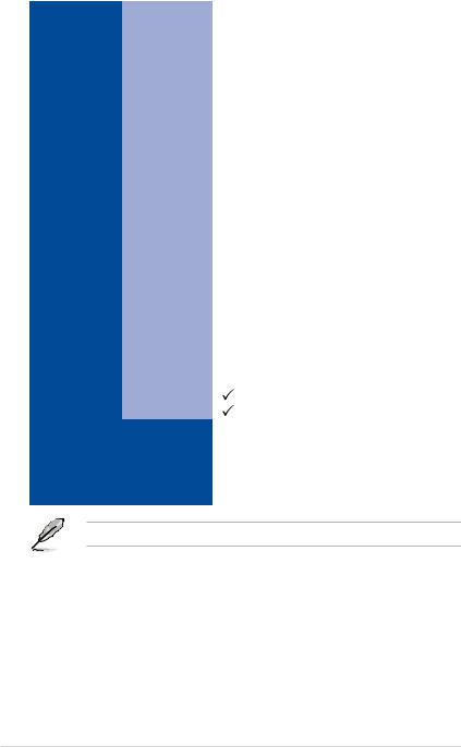
Specifications Summary
|
|
1 x Socket LGA1151 |
|
|
|
Intel® Xeon® processor E3-1200 v5 product family |
|
Processor Support / System Bus |
Intel® Core™ i3 processors |
||
|
|
Intel® Pentium™ processors |
|
|
|
Intel® Celeron™ processors |
|
Core Logic |
|
Intel® C232 Chipset |
|
Form Factor |
|
Mini-ITX, 6.7” x 6.7” |
|
|
Fan Speed Control |
|
|
|
|
|
|
ASUS Features |
Rack Ready |
|
|
(Rack and Pedestal |
|
||
|
dual use) |
|
|
|
ASWM Enterprise |
|
|
|
|
|
|
|
Total Slots |
2 (2 Channels) |
|
|
Voltage |
1.2V |
|
Memory |
Capacity |
Maximum up to 32GB |
|
|
Memory Type |
DDR4 2133 ECC/non-ECC UDIMM |
|
|
Memory Size |
16GB |
|
|
Total PCI/PCI-E Slots |
1 |
|
|
Slot Location 1 |
- |
|
Expansion |
Slot Location 2 |
- |
|
Slots |
|
|
|
Slot Location 3 |
- |
||
(follow SSI |
|||
Slot Location 4 |
- |
||
Location |
|||
Slot Location 5 |
- |
||
number) |
|||
|
Slot Location 6 |
- |
|
|
Slot Location 7 |
1 x PCI-E x16 (x16 Gen3 Link) |
|
|
|
Intel® C232: |
|
|
|
- 6 x SATA 6Gb/s ports (4 by 1 mini-SAS HD |
|
|
|
Connector) with 1 x M.2 connector (NGFF |
|
|
SATA Controller |
2242, PCI-E Gen3X4 link or SATA signal, |
|
|
gray SATA port will disable when M.2 is SATA |
||
|
|
||
|
|
signal) |
|
Storage |
|
- Intel® RSTe (Windows & Linux) |
|
|
|
- (Support software RAID 0, 1, 10 & 5) |
|
|
|
Optional Kits: |
|
|
|
- ASUS PIKE II 3008-8i 8-port SAS 12G RAID |
|
|
SAS Controller |
card |
|
-ASUS PIKE II 3108-8i 8-port SAS 12G HW RAID card
*Refer to www.asus.com for the complete list of supported CPUs.
(continued on the next page)
xi
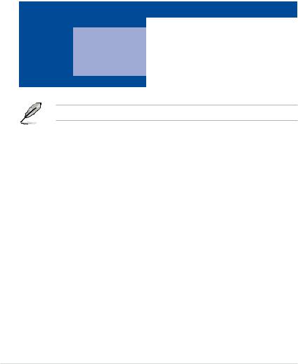
Networking |
LAN |
2 x Intel® I210AT + |
|
1 x Mgmt LAN |
|||
|
|
||
Graphic |
VGA |
Aspeed AST2400 32MB |
|
|
TPM Header |
1 |
|
|
PSU Connector |
20-pin ATX power connector + |
|
|
4-pin ATX 12V power connector |
||
|
|
||
|
Management |
Onboard header for optional management card |
|
|
Header |
||
|
|
||
Onboard I/O |
USB Connector/ |
1 x USB 3.0 connector (Type A USB socket) |
|
Header |
|||
Connectors |
|
||
Fan Header |
3 x 4 pin headers |
||
|
|||
|
SMBus connector |
1 |
|
|
Chassis Intruder |
1 |
|
|
Front LAN LED |
2 |
|
|
M.2 Connector |
1 |
|
|
External USB Port |
2 x USB 3.0 |
|
|
2 x USB 2.0 |
||
|
|
||
Rear I/O |
VGA Port |
1 |
|
Connectors |
RJ-45 |
2 x GbE LAN + |
|
|
1 x Mgmt LAN |
||
|
|
||
|
PS/2 KB/Mouse |
1 |
|
Management |
Software |
ASWM Enterprise |
|
|
|
||
Out of Band |
|
||
Solution |
Optional ASMB8-iKVM for KVM-over-Internet |
||
Remote |
|||
|
|||
|
Management |
|
|
Monitoring |
CPU Temperature |
|
|
|
|
||
FAN RPM |
|
||
|
|
||
|
|
|
|
|
|
Operation temperature: |
|
|
|
10oC – 35oC (50oF – 95oF) |
|
Environment |
|
Non operation temperature: |
|
|
-40oC – 70oC (-40oF – 158oF) |
||
|
|
Non operation humidity: |
|
|
|
20% – 90% (Non condensing) |
Specifications are subject to change without notice.
xii

Chapter 1:
Product Introduction
1.1Welcome!
Thank you for buying an ASUS® P10S-I motherboard!
The motherboard delivers a host of new features and latest technologies, making it another standout in the long line of ASUS quality motherboards!
Before you start installing the motherboard and hardware devices on it, check the items in your package with the list below.
1.2Package contents
Check your motherboard package for the following items.
|
Items |
Standard Gift Box Pack |
Standard Bulk Pack |
|
|
|
|
|
|
I/O Shield |
|
1 |
1 |
|
Cables |
SATA 6G cable |
2 |
-- |
|
COM port cable |
1 |
10 pcs per carton |
||
|
||||
Application CD |
Support CD |
1 |
1 pc per carton |
|
ASWM Enterprise SDVD |
1 |
1 pc per carton |
||
Accessory |
Metal Plate for LGA1151 |
1 |
1 |
|
Packaging Qty. |
|
1 pc per carton |
10 pcs per carton |
If any of the above items is damaged or missing, contact your retailer.
1-2 |
Chapter 1: Product Introduction |

1.3Serial number label
Before requesting support from the ASUS Technical Support team, you must take note of the motherboard's serial number containing 12 characters xxS2xxxxxxxx shown as the figure below. With the correct serial number of the product, ASUS Technical Support team members can then offer a quicker and satisfying solution to your problems.
P10S-I |
Made |
|
in |
|
China |
xxS2xxxxxxxx |
|
|
1.4Special features
1.4.1Product highlights
Latest processor technology
This motherboard supports the latest Intel® Xeon® Processor E3-1200 v5/ Core™ i3 series in LGA1151 package, which has memory and PCI Express controller integrated to support 2-channel (4 DIMMs) DDR4 memory and 16 PCI Express 3.0 lanes. The Intel® Xeon® E31200 v5 have improve CPU performance and integrated voltage regulators making it one of the most powerful and energy efficient CPU in the world.
Intel® Turbo Boost
Intel® Turbo Boost automatically allows the processor to run faster than the marked frequency if the processor is operating below its power, current, and temperature specification
limits. This technology increases performance of both multi-threaded and single-threaded workloads.
Intel® Hyper Threading
The thread-level parallelism on each processor makes more efficient use of the processor resources, higher processing throughout and improved performance on today's multithreaded software.
Intel® EM64T
The motherboard supports Intel® processors with the Intel® EM64T (Extended Memory 64 Technology). The Intel® EM64T feature allows your computer to run on 64-bit operating systems and access larger amounts of system memory for faster and more efficient computing.
DDR4 memory support
The motherboard supports DDR4 memory that features faster clock frequencies and higher data transfer rates of 2133 MT/s (million transfers per second). DDR4 offers a lower voltage standard of 1.2V that reduces memory power demand and provides improved performance.
ASUS P10S-I |
1-3 |

PCI Express 3.0
PCI Express 3.0 (PCIe 3.0) is the PCI Express bus standard that provides twice the performance and speed of PCIe 2.0. It provides an optimal graphics performance, unprecedented data speed, and seamless transition with its complete backward compatibility to PCIe 1.0/2.0 devices.
Intel® I210AT LAN Solution
The motherboard comes with two Gigabit LAN controllers and ports which provide a total solution for your networking needs. The onboard Intel® I210AT Gigabit LAN controllers use the PCI Express interface and could achieve network throughput close to Gigabit bandwidth.
Enhanced Intel SpeedStep Technology (EIST)
The Enhanced Intel SpeedStep Technology (EIST) intelligently manages the CPU resources by automatically adjusting the CPU voltage and core frequency depending on the CPU loading and system speed or power requirement.
Serial ATA III technology
The motherboard supports the Serial ATA III 6 Gb/s technology through the Serial ATA interface and Intel® C232 chipset. Get enhanced scalability, faster data retrieval, double the bandwidth of current bus systems with up to 6Gbps data transfer rates.
USB 2.0 technology
The motherboard implements the Universal Serial Bus (USB) 2.0 specification that dramatically increases the connection speed from the 12 Mbps bandwidth on USB 1.1 to a fast 480 Mbps on USB 2.0. USB 2.0 is backward compatible with USB 1.1.
USB 3.0 technology
The motherboard implements the USB 3.0 technology with data transfer speeds of up to
5Gbps, faster charging time for USB-chargeable devices, optimized power efficiency, and backward compatibility with USB 2.0.
Temperature, fan, and voltage monitoring
The CPU temperature is monitored to prevent overheating and damage. The system fan rotations per minute (RPM) is monitored for timely failure detection. The chip monitors the voltage levels to ensure stable supply of current for critical components.
1.4.2Innovative ASUS features
ASUS Fan Speed technology
The ASUS Fan Speed technology smartly adjusts the fan speeds according to the system loading to ensure quiet, cool, and efficient operation.
1-4 |
Chapter 1: Product Introduction |

Chapter 2:
Hardware Information

2.1Before you proceed
Take note of the following precautions before you install motherboard components or change any motherboard settings.
• Unplug the power cord from the wall socket before touching any component.
• Use a grounded wrist strap or touch a safely grounded object or a metal object, such as the power supply case, before handling components to avoid damaging them due to static electricity.
•Hold components by the edges to avoid touching the ICs on them.
•Whenever you uninstall any component, place it on a grounded antistatic pad or in the bag that came with the component.
•Before you install or remove any component, ensure that the power supply is switched off or the power cord is detached from the power supply. Failure to do so may cause severe damage to the motherboard, peripherals, and/or components.
2-2 |
Chapter 2: Hardware Information |
2.2Motherboard overview
Before you install the motherboard, study the configuration of your chassis to ensure that the motherboard fits into it.
To optimize the motherboard features, we highly recommend that you install it in an ATX 1.1 compliant chassis.
Ensure to unplug the chassis power cord before installing or removing the motherboard. Failure to do so can cause you physical injury and damage motherboard components!
2.2.1Placement direction
When installing the motherboard, ensure that you place it into the chassis in the correct orientation. The edge with external ports goes to the rear part of the chassis as indicated in the image below.
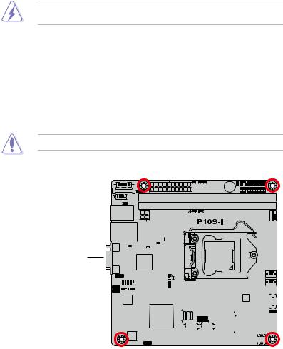
2.2.2Screw holes
Place four (4) screws into the holes indicated by circles to secure the motherboard to the chassis.
DO NOT overtighten the screws! Doing so can damage the motherboard.
Place this side towards the rear of the chassis
|
|
|
|
|
|
|
|
|
|
|
|
|
|
|
|
|
|
|
|
|
|
|
|
|
|
|
|
|
|
|
|
|
|
|
|
|
|
|
|
|
|
|
|
|
|
|
|
|
|
|
|
|
|
|
|
|
|
|
|
|
|
|
|
|
|
|
|
|
|
|
|
|
|
|
|
|
|
|
|
|
|
|
|
|
|
|
|
|
|
|
|
|
|
|
|
|
|
|
|
|
|
|
|
|
|
|
|
|
|
|
|
|
|
|
|
|
|
|
|
|
|
|
|
|
|
|
|
|
|
|
|
|
|
|
|
|
|
|
|
|
|
|
|
|
|
|
|
|
|
|
|
|
|
|
|
|
|
|
|
|
|
|
|
|
|
|
|
|
|
|
|
|
|
|
|
|
|
|
|
|
|
|
|
|
|
|
|
|
|
|
|
|
|
|
|
|
|
|
|
|
|
|
|
|
|
|
|
|
|
|
|
|
|
|
|
|
|
|
|
|
|
|
|
|
|
|
|
|
|
|
|
|
|
|
|
|
|
|
|
|
|
|
|
|
|
|
|
|
|
|
|
|
|
|
|
|
|
|
|
|
|
|
|
|
|
|
|
|
|
|
|
|
|
|
|
|
|
|
|
|
|
|
|
|
|
|
|
|
|
|
|
|
|
|
|
|
|
|
|
|
|
|
|
|
|
|
|
|
|
|
|
|
|
|
|
|
|
|
|
|
|
|
|
|
|
|
|
|
|
|
|
|
|
|
|
|
|
|
|
|
|
|
|
|
|
|
|
|
|
|
|
|
|
|
|
|
|
|
|
|
|
|
|
|
|
|
|
|
|
|
|
|
|
|
|
|
|
|
|
|
|
|
|
|
|
|
|
|
|
|
|
|
|
|
|
|
|
|
|
|
|
|
|
|
|
|
|
ASUS P10S-I |
2-3 |
||||||||||||||||||||||||||||||||
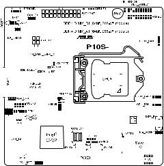
2.2.3Motherboard layout
|
|
|
|
|
|
|
|
|
|
|
|
|
|
|
|
|
|
|
|
|
|
|
|
|
|
|
|
|
|
|
|
|
|
|
|
|
|
|
|
|
|
|
|
|
|
|
|
|
|
|
|
|
|
|
|
|
|
|
|
|
|
|
|
|
|
|
|
|
|
|
|
|
|
|
|
|
|
|
|
|
|
|
|
|
|
|
|
|
|
|
|
|
|
|
|
|
|
|
|
|
|
|
|
|
|
|
|
|
|
|
|
|
|
|
|
|
|
|
|
|
|
|
|
|
|
|
|
|
|
|
|
|
|
|
|
|
|
|
|
|
|
|
|
|
|
|
|
|
|
|
|
|
|
|
|
|
|
|
|
|
|
|
|
|
|
|
|
|
|
|
|
|
|
|
|
|
|
|
|
|
|
|
|
|
|
|
|
|
|
|
|
|
|
|
|
|
|
|
|
|
|
|
|
|
|
|
|
|
|
|
|
|
|
|
|
|
|
|
|
|
|
|
|
|
|
|
|
|
|
|
|
|
|
|
|
|
|
|
|
|
|
|
|
|
|
|
|
|
|
|
|
|
|
|
|
|
|
|
|
|
|
|
|
|
|
|
|
|
|
|
|
|
|
|
|
|
|
|
|
|
|
|
|
|
|
|
|
|
|
|
|
|
|
|
|
|
|
|
|
|
|
|
|
|
|
|
|
|
|
|
|
|
|
|
|
|
|
|
|
|
|
|
|
|
|
|
|
|
|
|
|
|
|
|
|
|
|
|
|
|
|
|
|
|
|
|
|
|
|
|
|
|
|
|
|
|
|
|
|
|
|
|
|
|
|
|
|
|
|
|
|
|
|
|
|
|
|
|
|
|
|
|
|
|
|
|
|
|
|
|
|
|
|
|
|
|
|
|
|
|
|
|
|
|
|
|
|
|
|
|
|
|
|
|
|
|
|
|
|
|
|
|
|
|
|
|
|
|
|
|
|
|
|
|
|
|
|
|
|
|
|
|
|
|
|
|
|
|
|
|
|
|
|
|
|
|
|
|
|
|
|
|
|
|
|
|
|
|
|
|
|
|
|
|
|
|
|
|
|
|
|
|
|
|
|
|
|
|
|
|
|
|
|
|
|
|
|
|
|
|
|
|
|
|
|
|
|
|
|
|
|
|
|
|
|
|
|
|
|
|
|
|
|
|
|
|
|
|
|
|
|
|
|
|
|
|
|
|
|
|
|
|
|
|
|
|
|
|
|
|
|
|
|
|
|
|
|
|
|
|
|
|
|
|
|
|
|
|
|
|
|
|
|
|
|
|
|
|
|
|
|
|
|
|
|
|
|
|
|
|
|
|
|
|
|
|
|
|
|
|
|
|
|
|
|
|
|
|
|
|
|
|
|
|
|
|
|
|
|
|
|
|
|
|
|
|
|
|
|
|
|
|
|
|
|
|
|
|
|
|
|
|
|
|
|
|
|
|
|
|
|
|
|
|
|
|
|
|
|
|
|
|
|
|
|
|
|
|
|
|
|
|
|
|
|
|
|
|
|
|
|
|
|
|
|
|
|
|
|
|
|
|
|
|
|
|
|
|
|
|
|
|
|
|
|
|
|
|
|
|
|
|
|
|
|
|
|
|
|
|
|
|
|
|
|
|
|
|
|
|
|
|
|
|
|
|
|
|
|
|
|
|
|
|
|
|
|
|
|
|
|
|
|
|
|
|
|
|
|
|
|
|
|
|
|
|
|
|
|
|
|
|
|
|
|
|
|
|
|
|
|
|
|
|
|
|
|
|
|
|
|
|
|
|
|
|
|
|
|
|
|
|
|
|
|
|
|
|
|
|
|
|
|
|
|
|
|
|
|
|
|
|
|
|
|
|
|
|
|
|
|
|
|
|
|
|
|
|
|
|
|
|
|
|
|
|
|
|
|
|
|
|
|
|
|
|
|
|
|
|
|
|
|
|
|
|
|
|
|
|
|
|
|
|
|
|
|
|
|
|
|
|
|
|
|
|
|
|
|
|
|
|
|
|
|
|
|
|
|
|
|
|
|
|
|
|
|
|
|
|
|
2-4 |
|
|
|
|
|
|
|
|
|
|
|
|
|
|
|
|
|
|
|
|
|
|
|
|
|
|
|
|
|
|
|
|
|
|
|
|
Chapter 2: Hardware Information |
||||||||||
2.2.4Layout contents
Slots/Sockets |
Page |
|
|
|
|
1. |
CPU sockets |
2-7 |
|
|
|
2. |
DDR4 sockets |
2-13 |
|
|
|
3. |
PCI Express x16 slot |
2-17 |
|
|
|
Onboard LEDs |
Page |
|
|
|
|
1. |
Standby Power LED (SBPWR1) |
2-19 |
|
|
|
2. |
Location LED (LOCLED1) |
2-19 |
|
|
|
3. |
CATT ERR LED (CATTERR1) |
2-20 |
|
|
|
4. |
Baseboard Management Controller LED (BMCLED1) |
2-20 |
|
|
|
5. |
CPU Warning LED (ERRCPU1) |
2-21 |
|
|
|
Jumpers |
|
Page |
|
|
|
1. |
Clear RTC RAM (3-pin CLRTC1) |
2-22 |
|
|
|
2. |
VGA controller setting (3-pin VGA_SW1) |
2-23 |
|
|
|
3. |
LAN controller setting (3-pin LAN_SW1, LAN_SW2) |
2-23 |
|
|
|
4. |
ME firmware force recovery setting (3-pin ME_RCVR1) |
2-24 |
5. |
PCH_MFG1 setting (3-pin PCH_MFG1) |
2-24 |
Rear panel connectors |
Page |
|
|
|
|
1. |
PS/2 keyboard/mouse port |
2-25 |
|
|
|
2. |
RJ-45 port for iKVM |
2-25 |
|
|
|
3. |
Video Graphics Adapter port |
2-25 |
|
|
|
4. |
RJ-45 ports for LAN 12 |
2-25 |
|
|
|
5. |
USB 2.0 ports 3 and 4 |
2-25 |
|
|
|
6. |
USB 3.0 ports 1 and 2 |
2-25 |
|
|
|
ASUS P10S-I |
2-5 |

Internal connectors |
Page |
|
|
|
|
1. |
Serial ATA 6.0 Gbps connectors (7-pin SATA 6Gbps_5 |
2-28 |
|
connector [Light Blue], SATA 6Gbps_6 connector [Gray]) |
|
|
|
|
|
|
|
2. |
Mini-SAS HD connector (SATA1234) |
2-28 |
|
|
|
3. |
USB 2.0 connector (10-1 pin USB78) |
2-29 |
4. |
USB 3.0 connector (A-Type USB3_5) |
2-29 |
5. |
Front fan connectors (4-pin CPU_FAN1, FRNT_FAN1-2) |
2-30 |
6. |
Serial General Purpose Input/Output connector (6-1 pin SGPIO1) |
2-30 |
|
|
|
7. |
Trusted Platform Module connector (14-1 pin TPM1) |
2-31 |
|
|
|
8. |
Power Supply SMBus connector (5-pin PSUSMB1) |
2-31 |
|
|
|
9. |
M.2 (NGFF) connector (NGFF1) |
2-32 |
|
|
|
10. |
Chassis Intrusion (2-pin INTRUSION) |
2-32 |
|
|
|
11. |
ATX power connectors (20-pin EATXPWR1, 4-pin EATX12V1) |
2-33 |
|
|
|
12. |
Hard disk activity LED connector (4-pin HDLED1) |
2-33 |
|
|
|
13. |
System panel connector (20-1 pin PANEL1) |
2-34 |
14. |
Auxiliary panel connector (20-2 pin AUX_PANEL1) |
2-35 |
|
|
|
15. |
Serial port connector (10-1 pin COM1) |
2-36 |
|
|
|
16. |
System Management Bus (SMBUS) connector |
2-36 |
|
(5-1 pin SMBUS1) |
|
|
|
|
2-6 |
Chapter 2: Hardware Information |
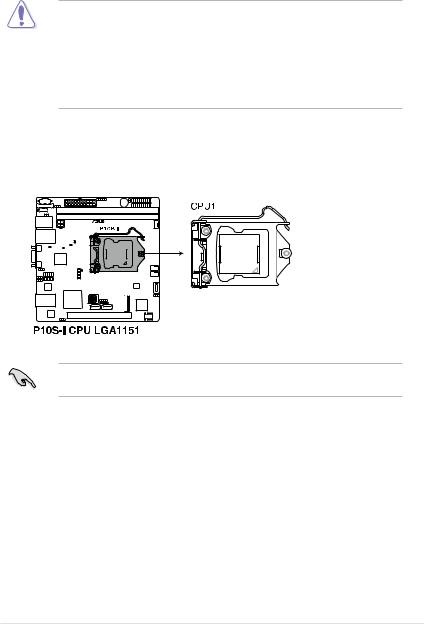
2.3Central Processing Unit (CPU)
The motherboard comes with a surface mount LGA1151 socket designed for the Intel® Xeon® E3-1200 v5 and Intel® Core™ i3 processor.
•Upon purchase of the motherboard, ensure that the PnP cap is on the socket and
the socket contacts are not bent. Contact your retailer immediately if the PnP cap is missing, or if you see any damage to the PnP cap/socket contacts/motherboard components. ASUS will shoulder the cost of repair only if the damage is shipment/ transit-related.
•The product warranty does not cover damage to the socket contacts resulting from incorrect CPU installation/removal, or misplacement/loss/incorrect removal of the PnP cap.
2.3.1Installing the CPU
To install the CPU:
1.Locate the CPU socket on the motherboard.
Before installing the CPU, ensure that the socket box is facing toward you and the load lever is on your right.
ASUS P10S-I |
2-7 |
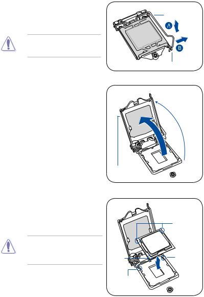
2.Press the load lever with your thumb
(A), then move it to the right (B) until it is released from the retention tab.
Do not remove the PnP cap yet from the CPU socket. Doing so may bend the pins of the socket.
3.Lift the load lever until the load plate is completely lifted.
Load plate
Load lever
Retention tab
4.Position the CPU above the socket, ensuring that the gold triangle mark is on the bottom-left corner of the socket, then fit the CPU notches to the socket's alignment keys.
The CPU fits in only one orientation. DO NOT force the CPU into the socket to prevent bending the pins on the socket and damaging the CPU.
Gold triangle mark
Alignment
key
CPU notches
Alignment key
2-8 |
Chapter 2: Hardware Information |

5.Close the load plate (A), ensuring that the front edge of the load plate
slides under the retention lock (B) |
Load lever |
|
|
then push down the load lever (C). |
|
Retention lock
6.Insert the load lever under the retention tab to remove the PnP cap from the CPU socket.
Load lever
 Retention tab
7.Apply some Thermal Interface Material
to the exposed area of the CPU that the heatsink will be in contact with, ensuring that it is evenly spread in a thin layer.
Some heatsinks come with preapplied Thermal Interface Material. If so, skip this step.
The Thermal Interface Material is toxic and inedible. DO NOT eat it. If it gets into your eyes or touches your skin, wash it off immediately and seek professional medical help.
ASUS P10S-I |
2-9 |
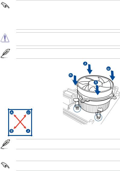
2.3.2Installing the CPU heatsink
The Intel® LGA1151 processor requires a specially designed CPU heatsink to ensure optimum thermal condition and performance.
•When you buy a boxed Intel® processor, a specially designed CPU heatsink or a
CPU heatsink with a CPU fan assembly is included depending on the package. If you buy a CPU separately, ensure that you use only Intel® certified multi directional CPU heatsink or CPU heatsink with CPU fan.
•Use an LGA1151-compatible CPU heatsink and CPU fan assembly only. The LGA1151 socket is incompatible with the LGA775 and LGA1366 sockets in size and dimension.
If you purchased a separate CPU heatsink and fan assembly, ensure that the Thermal Interface Material is properly applied to the CPU heatsink or CPU before you install the heatsink and fan assembly.
Ensure that you have installed the motherboard to the chassis before you install the CPU fan and heatsink assembly.
To install the CPU heatsink and fan:
1. Place the heatsink on top of the installed CPU, making sure that the four fasteners match the holes on the motherboard.
2. Push down two fasteners at a time in a diagonal sequence to secure the heatsink and fan assembly in place.
Orient the heatsink and fan assembly such that the CPU fan cable is closest to the CPU fan connector.
3.Connect the CPU fan cable to the connector on the motherboard labeled CPU_FAN1.
DO NOT forget to connect the CPU fan connector! Hardware monitoring errors can occur if you fail to plug this connector.
2-10 |
Chapter 2: Hardware Information |
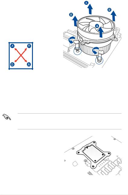
2.3.3Uninstalling the CPU heatsink and fan
To uninstall the CPU heatsink and fan:
1.Disconnect the CPU fan cable from the connector on the motherboard.
2. Rotate each fastener counterclockwise.
3.Pull up two fasteners at a time in a diagonal sequence to disengage the heatsink and fan assembly from the motherboard.
4.Carefully remove the heatsink and fan assembly from the motherboard.
2.3.4Installing the CPU heatsink in rack
The Intel® LGA1151 processor requires a specially designed heatsink to ensure optimum thermal condition and performance.
• Ensure that you use qualified heatsink assembly only.
•Ensure that you have applied the thermal interface material to the top of the CPU before installing the heatsink and fan.
1. Peel off the sticker on the heatsink metal plate and affix the plate to the back of the motherboard, matching the standoffs to the heatsink screw holes.
ASUS P10S-I |
2-11 |
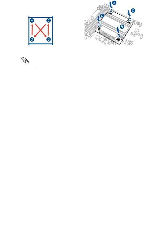
2.Use a Phillips screwdriver to tighten
the four heatsink screws using the recommended sequence below.
•Ensure that the heatsink is not skewed or tilted, otherwise the CPU will overheat.
•Do not overtighten the screws. Doing so can damage the CPU.
2-12 |
Chapter 2: Hardware Information |
2.4System memory
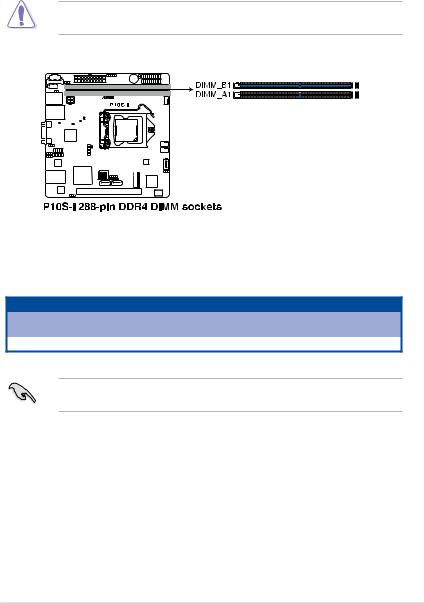
2.4.1Overview
The motherboard comes with two Double Data Rate 4 (DDR4) Dual Inline Memory Modules (DIMM) sockets.
A DDR4 module is notched differently from a DDR, DDR2, or DDR3 module. DO NOT install a DDR, DDR2, or DDR3 memory module to the DDR4 slot.
The figure illustrates the location of the DDR4 DIMM sockets:
2.4.2Memory configurations
You may install Unbuffered DDR4 DIMMs into the DIMM sockets using the memory configurations in this section.
UDIMM
DIMM Slot Per |
DIMM Populated |
DIMM Type |
Speed |
Rank per DIMM |
|
Channel |
per Channel |
||||
|
|
|
|||
1 |
1 |
Unbuffered DDR4 |
2133 |
Single Rank, Dual Rank |
Always install DIMMs with the same CAS latency. For optimum compatibility, it is recommended that you obtain memory modules from the same vendor.
ASUS P10S-I |
2-13 |
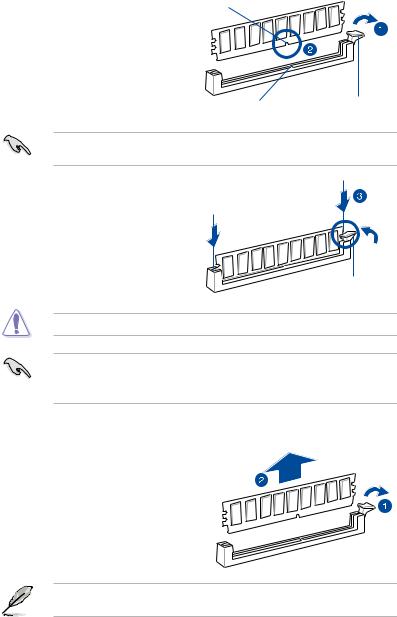
2.4.3Installing a DIMM on a single clip DIMM socket
1. |
Unlock a DIMM socket by pressing the DIMM notch |
|
|
retaining clip outward. |
|
2. |
Align a DIMM on the socket such that |
|
|
the notch on the DIMM matches the |
|
|
DIMM slot key on the socket. |
|
|
DIMM slot key |
Unlocked retaining clip |
A DIMM is keyed with a notch so that it fits in only one direction. DO NOT force a DIMM into a socket in the wrong direction to avoid damaging the DIMM.
3.Hold the DIMM by both of its ends
then insert the DIMM vertically into the socket. Apply force to both ends of the DIMM simultaneously until the retaining clip snaps back into place and the
DIMM cannot be pushed in any further to ensure proper sitting of the DIMM.
Locked Retaining Clip
Always insert the DIMM into the socket vertically to prevent DIMM notch damage.
•To install two or more DIMMs, refer to the user guide bundled in the motherboard
package.
•Refer to the user guide for qualified vendor lists of the memory modules.
Removing a DIMM from a single clip DIMM socket
1.Press the retaining clip outward to unlock the DIMM.
2. Remove the DIMM from the socket.
Support the DIMM lightly with your fingers when pressing the retaining clips. The DIMM might get damaged when it flips out with extra force.
2-14 |
Chapter 2: Hardware Information |
Loading...