


 Loading...
Version 1.0
Published January 2019
Copyright©2019 ASRock Rack Inc. All rights reserved.
Copyright Notice:
No part of this documentation may be reproduced, transcribed, transmitted, or translated in any language, in any form or by any means, except duplication of documentation by the purchaser for backup purpose, without written consent of ASRock Rack Inc.
Products and corporate names appearing in this documentation may or may not be registered trademarks or copyrights of their respective companies, and are used only for
identification or explanation and to the owners’ benefit, without intent to infringe.
Disclaimer:
Specifications and information contained in this documentation are furnished for informational use only and subject to change without notice, and should not be constructed as a commitment by ASRock Rack. ASRock Rack assumes no responsibility for any errors or omissions that may appear in this documentation.
With respect to the contents of this documentation, ASRock Rack does not provide warranty of any kind, either expressed or implied, including but not limited to the implied warranties or conditions of merchantability or fitness for a particular purpose.
In no event shall ASRock Rack, its directors, officers, employees, or agents be liable for any indirect, special, incidental, or consequential damages (including damages for loss of profits, loss of business, loss of data, interruption of business and the like), even if ASRock Rack has been advised of the possibility of such damages arising from any defect or error in the documentation or product.
This device complies with Part 15 of the FCC Rules. Operation is subject to the following two conditions:
(1)this device may not cause harmful interference, and
(2)this device must accept any interference received, including interference that may cause undesired operation.
CALIFORNIA, USA ONLY
The Lithium battery adopted on this motherboard contains Perchlorate, a toxic substance controlled in Perchlorate Best Management Practices (BMP) regulations passed by the California Legislature. When you discard the Lithium battery in California, USA, please follow the related regulations in advance.
“Perchlorate Material-special handling may apply, see www.dtsc.ca.gov/hazardouswaste/ perchlorate”
ASRock Rack’s Website: www.ASRockRack.com
Contact Information
If you need to contact ASRock Rack or want to know more about ASRock Rack, you’re welcome to visit ASRock Rack’s website at www.ASRockRack.com; or you may contact your dealer for further information.
ASRock Rack Incorporation
6F., No.37, Sec. 2, Jhongyang S. Rd., Beitou District,
Taipei City 112, Taiwan (R.O.C.)
Contents |
|
|
Chapter 1 Introduction |
1 |
|
1.1 |
Package Contents |
1 |
1.2 |
Specifications |
2 |
1.3 |
Unique Features |
5 |
1.4 |
Motherboard Layout |
6 |
1.5 |
Onboard LED Indicators |
8 |
1.6 |
I/O Panel |
10 |
1.7 |
Block Diagram |
12 |
Chapter 2 Installation |
13 |
|
2.1 |
Screw Holes |
13 |
2.2 |
Pre-installation Precautions |
13 |
2.3 |
Installing the CPU |
14 |
2.4 |
Installing the CPU Fan and Heatsink |
16 |
2.5 |
Installing Memory Modules (DIMM) |
19 |
2.6 |
Expansion Slots (PCI Express Slots) |
21 |
2.7 |
Jumpers Setup |
22 |
2.8 |
Onboard Headers and Connectors |
24 |
2.9 |
Dr. Debug |
29 |
2.10 |
Unit Identification purpose LED/Switch |
30 |
2.11 |
Driver Installation Guide |
30 |
2.12 |
M.2_SSD (NGFF) Module Installation Guide |
31 |
Chapter 3 UEFI Setup Utility |
33 |
|
3.1 |
Introduction |
33 |
3.1.1 |
UEFI Menu Bar |
33 |
3.1.2 |
Navigation Keys |
34 |
3.2 |
Main Screen |
35 |
3.3 |
Advanced Screen |
36 |
3.3.1 |
CPU Configuration |
37 |
3.3.2 |
Chipset Configuration |
38 |
3.3.3 |
Storage Configuration |
40 |
3.3.4 |
ACPI Configuration |
41 |
3.3.5 |
USB Configuration |
42 |
3.3.6 |
Super IO Configuration |
43 |
3.3.7 |
Serial Port Console Redirection |
44 |
3.3.8 |
H/W Monitor |
48 |
3.3.9 |
AMD CBS |
50 |
3.3.10 |
AMD PBS |
51 |
3.3.11 |
Instant Flash |
54 |
3.4 |
Server Mgmt |
55 |
3.4.1 |
System Event Log |
56 |
3.4.2 |
BMC Network Configuration |
57 |
3.5 |
Security |
59 |
3.5.1 |
Key Management |
60 |
3.6 |
Boot Screen |
63 |
3.6.1 |
CSM Parameters |
65 |
3.7 |
Exit Screen |
67 |
Chapter 4 Software Support |
68 |
|
4.1 |
Install Operating System |
68 |
4.2 |
Support CD Information |
68 |
4.2.1 |
Running The Support CD |
68 |
4.2.2 |
Drivers Menu |
68 |
4.2.3 |
Utilities Menu |
68 |
4.2.4 |
Contact Information |
68 |
Chapter 5 Troubleshooting |
69 |
|
5.1 |
Troubleshooting Procedures |
69 |
5.2 |
Technical Support Procedures |
71 |
5.3 |
Returning Merchandise for Service |
71 |
X470D4U2-2T
Chapter 1 Introduction
Thank you for purchasing ASRock Rack X470D4U2-2T motherboard, a reliable motherboard produced under ASRock Rack’s consistently stringent quality control. It delivers excellent performance with robust design conforming to ASRock Rack’s commitment to quality and endurance.
In this manual, chapter 1 and 2 contains introduction of the motherboard and step- by-step guide to the hardware installation. Chapter 3 and 4 contains the configuration guide to BIOS setup and information of the Support CD.
Because the motherboard specifications and the BIOS software might be updated, the content of this manual will be subject to change without notice. In case any modifications of this manual occur, the updated version will be available on ASRock Rack website without further notice. You may find the latest memory and CPU support lists on ASRock Rack website as well. ASRock Rack’s Website: www.ASRockRack.com
If you require technical support related to this motherboard, please visit our website for specific information about the model you are using. http://www.asrockrack.com/support/
1.1 Package Contents
•ASRock Rack X470D4U2-2T Motherboard
(micro-ATX Form Factor: 9.6-in x 9.6-in, 24.4 cm x 24.4 cm)
•Quick Installation Guide
•1 x I/O Shield
•1 x SATA3 Cable (60cm)
•2 x Screws for M.2 Sockets
If any items are missing or appear damaged, contact your authorized dealer.
English
1

English
1.2 Specifications
X470D4U2-2T
|
MB Physical Status |
|
|
|
Form Factor |
|
micro-ATX |
|
|
||
|
Dimension |
|
9.6'' x 9.6'' (24.4 cm x 24.4 cm) |
|
Processor System |
|
|
|
CPU |
|
AMD AM4 Socket Ryzen Series CPUs (Raven Ridge and |
|
|
|
Pinnacle Ridge) and Ryzen 7nm CPUs |
|
Socket |
|
AM4 PGA 1331 |
|
Chipset |
|
AMD X470 |
|
System Memory |
|
|
|
Capacity |
|
- 4 x 288-pin DDR4 DIMM slots |
|
|
|
- Support up to 64GB DDR4 ECC/UDIMM |
|
|
|
- One DIMM: 1R DIMM @2667MT/s; 2R/2DR DIMM |
|
|
|
@2400MT/s |
|
|
|
- Two DIMMs: (2) 1R DIMM @2133 MT/s; (2) 2R/2DR DIMM |
|
|
|
@1866MT/s; 1R and 2R/2DR DIMM each @1866MT/s |
|
Type |
|
- Dual Channel DDR4 memory technology |
|
|
|
- Support DDR4 ECC/UDIMM |
|
DIMM Size Per |
|
- ECC/UDIMM: 64GB, 32GB, 16GB, 8GB |
|
DIMM |
|
|
|
DIMM Frequency |
|
- ECC/UDIMM: 2666/2400/2133 MHz |
|
Voltage |
|
1.2V |
|
Expansion Slot |
|
|
|
PCIe 3.0 x 16 |
|
PCIE6: Gen3 x16 link (splittable in x4/4/4/4); auto switch to x8 |
|
|
|
link when PCIE4 is occupied. |
|
|
|
PCIE4: Gen3 x8 link |
|
PCIe 2.0 x 1 |
|
PCIE5: Gen2 x1 link |
|
Storage |
|
|
|
SATA Controller |
|
6 x SATA3 6.0 Gb/s (1x SATA DOM port), support RAID 0, 1, |
|
|
|
10 |
|
M.2 Slot |
|
2 (2242/2260/2280/22110, supports SATA3 and PCIe 3.0 x2 or |
|
|
|
supports PCIe 2.0 x4 only) |
|
Ethernet |
|
|
|
Interface |
|
10000/1000 /100 /10 Mbps |
|
LAN Controller |
|
- 2 x RJ45 10G base-T by Intel® X550-AT2 |
|
|
|
- 1 x RJ45 Dedicated IPMI LAN port by RTL8211E |
|
|
|
- Supports Wake-On-LAN |
|
|
|
- Supports Energy Efficient Ethernet 802.3az |
|
|
|
- Supports Dual LAN with Teaming function |
|
|
|
- Supports PXE |
2 |
|
|
- LAN3 supports NCSI |
|
|
|

|
|
|
|
X470D4U2-2T |
|
|
|
|
|
||
|
|
|
|
|
|
|
Management |
|
|
|
|
|
BMC Controller |
ASPEED AST2500 |
|
||
|
IPMI Dedicated |
1 x Realtek RTL8211E for dedicated management GLAN |
|
||
|
GLAN |
|
|
|
|
|
Features |
Watch Dog |
|
||
|
Graphics |
|
|
|
|
|
Controller |
ASPEED AST2500 |
|
||
|
VRAM |
DDR4 256MB |
|
||
|
Rear Panel I/O |
|
|
|
|
|
VGA Port |
1 x D-Sub |
|
||
|
Serial Port |
1 x COM port |
|
||
|
USB 3.1 (Gen1) |
2 |
|
|
|
|
Port |
|
|
|
|
|
LAN Port |
- 2 x RJ45 10 Gigabit Ethernet LAN ports |
|
||
|
|
- 1 x RJ45 Dedicated IPMI LAN port |
|||
|
|
- LAN Ports with LED (ACT/LINK LED and SPEED LED) |
|||
|
UID |
1 |
|
|
|
|
Internal Connector |
|
|
|
|
|
Auxiliary Panel |
1 |
(includes chassis intrusion, location button & LED, front |
|
|
|
Header |
LAN LED, system fault, and BMC alert) |
|||
|
TPM Header |
1 |
|
|
|
|
IPMB Header |
1 |
|
|
|
|
Fan Header |
6 Fans x 4-pin (FAN1(CPU)/FAN2~FAN6(5Front)) |
|
||
|
ATX Power |
1 x (24-pin) + 1 x (8-pin) |
|
||
|
USB 3.1 Gen1 |
1 |
(supports 2 USB 3.1 Gen1 ports) |
|
|
|
Header |
|
|
|
|
|
M.2 |
2(M2_1: 2242/2260/2280/22110, PCIE(X4); |
|
||
|
|
M2_2:2242/2260/2280/22110, SATA/PCIE(X2)) |
|||
|
SATA DOM |
1 |
|
|
|
|
BMC_SMB1 |
1 |
|
|
|
|
PSU_SMB1 |
1 |
|
|
|
|
80 debug port LED |
1 |
|
|
|
|
Buzzer |
1 |
|
|
|
|
Clear CMOS |
1 |
(short pad) |
|
|
|
OH/FanFail LED |
6 |
(only Fan Fail LED) |
|
|
|
Front Panel |
1 |
(RST, PWRBTN, HDDLED, PWRLED) |
|
|
|
System BIOS |
|
|
|
|
|
BIOS Type |
16MB AMI UEFI Legal BIOS |
|
||
|
BIOS Features |
- Plug and Play (PnP) |
|
||
|
|
- ACPI 2.0 Compliance Wake Up Events |
|||
|
|
- SMBIOS 2.8 Support |
|||
|
|
- ASRock Rack Instant Flash |
|
||
English
3
Hardware Monitor
Temperature |
- CPU/DDR/LAN Temperature Sensing |
|
- MB/Card Side Temperature Sensing |
Fan |
- Fan Tachometer |
|
- Quiet Fan (Allow Chassis Fan Speed Auto-Adjust by CPU |
|
Temperature) |
|
- Fan Multi-Speed Control |
Voltage |
Voltage Monitoring: +12V, +5V, +3.3V, CPU Vcore, DRAM, |
|
1.05V_PCH, +BAT, 3VSB, 5VSB |
Support OS |
|
OS |
Microsoft® Windows®: |
|
Windows 10 (64 bit) |
|
Linux®: |
|
- UBuntu 16.04.4 (64 bit) |
|
- RedHat Enterprise Linux Server 7.3 (64bit) / 7.4 (64bit) |
|
* Please refer to our website for the latest OS support list. |
|
* The Linux system doesn’t support Raid mode. |
|
* Supports UEFI BOOT only. |
Environment |
|
Temperature |
Operation temperature: 10°C ~ 35°C / Non operation |
|
temperature: -40°C ~ 70°C |
NOTE: Please refer to our website for the latest specifications.
This motherboard supports Wake from on Board LAN. To use this function, please make sure that the “Wake on Magic Packet from power off state” is enabled in Device Manager > Intel® Ethernet Connection > Power Management. And the “PCI Devices Power On” is enabled in UEFI SETUP UTILITY > Advanced > ACPI Configuration. After that, onboard LAN3&4 can wake up S5 under OS.
If you install Intel® LAN utility or Marvell SATA utility, this motherboard may fail Windows® Hardware Quality Lab (WHQL) certification tests. If you install the drivers only, it will pass the WHQL tests.
English
4
X470D4U2-2T
1.3 Unique Features
ASRock Rack Instant Flash is a BIOS flash utility embedded in Flash ROM. This convenient BIOS update tool allows you to update system BIOS without entering operating systems first like MS-DOS or Windows®. With this utility, you can press the <F6> key during the POST or the <F2> key to enter into the BIOS setup menu to access ASRock Rack Instant Flash. Just launch this tool and save the new BIOS file to your USB flash drive, floppy disk or hard drive, then you can update your BIOS only in a few clicks without preparing an additional floppy diskette or other complicated flash utility. Please be noted that the USB flash drive or hard drive must use FAT32/16/12
file system.
English
5
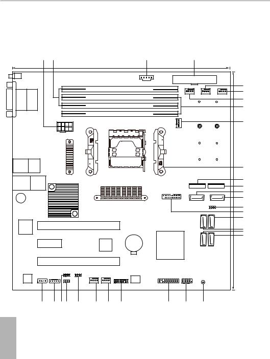
1.4 Motherboard Layout
|
|
1 |
2 |
|
|
|
|
|
|
3 |
|
|
4 |
|
|
|
|
|
|
|
|
|
|
24.4cm (9.6 in) |
|
|
|
|
|
||
UID1 |
|
|
|
|
X470D4U2-2T |
|
1 |
|
|
|
|
|
|||
|
|
|
|
|
|
|
|
|
|
|
|||||
|
|
|
|
|
|
|
|
ATXPWR1 |
|
||||||
|
|
|
|
|
|
|
|
|
|
PSU_SMB1 |
|
|
|||
|
|
|
|
|
|
|
|
|
|
|
|
|
|
|
|
|
|
|
|
|
|
|
|
DDR4_B1 (64 bit, 288-pin module) |
|
FAN2 |
|
|
5 |
||
|
|
|
|
|
|
|
|
|
|
|
|
|
|||
VGA1 |
COM1 |
|
|
|
|
|
|
|
|
|
|
|
|
6 |
|
|
|
|
|
|
|
|
|
|
|
FAN3 |
FAN4 |
|
|||
|
|
|
|
|
DDR4_B2 (64 bit, 288-pin module) |
|
|
|
|
7 |
|||||
|
|
|
|
|
|
|
|
|
|
|
|
||||
|
|
|
|
|
DDR4_A1 (64 bit, 288-pin module) |
|
|
NUT110_2 |
NUT110_1 |
8 |
|||||
|
|
|
|
|
|
|
|
|
|||||||
|
|
|
|
|
|
|
|
|
|
|
|
|
|
|
|
|
|
|
|
|
|
|
|
DDR4_A2 (64 bit, 288-pin module) |
|
|
|
|
|
||
|
|
|
|
|
|
|
|
|
|
|
|
|
|
|
9 |
|
|
|
|
|
|
|
|
|
|
|
|
FAN1 |
NUT80_2 |
NUT80_1 |
(9.6in) |
|
|
|
|
|
|
|
|
|
|
|
|
|
|||
|
|
|
|
|
ATX12V1 |
|
|
|
|
|
|
|
|
|
|
|
|
|
|
|
|
|
|
|
|
|
|
|
|
|
|
|
|
|
|
|
|
|
|
|
|
|
|
|
NUT60_2 |
NUT60_1 |
|
USB: USB2T: Gen1 1 |
US3.B 1 |
IPMILAN |
|
|
|
|
|
|
|
|
|
|
NUT42_2 |
NUT42_1 |
|
|
|
|
|
|
|
|
|
|
|
|
|
10 |
|||
|
|
|
|
|
|
Socket |
|
|
|
RoHS |
24.4cm |
||||
|
|
|
|
|
|
|
|
|
|
|
|
|
|
||
LAN3 |
LAN4 |
|
|
|
|
|
AM4 PGA 1331 |
|
|
|
|
11 |
|||
|
|
|
|
|
|
|
|
|
|
M2_2 |
M2_1 |
12 |
|||
|
|
|
|
|
|
|
|
|
|
|
|
|
|||
|
|
|
|
|
|
|
|
|
|
|
|
|
|
|
|
|
|
|
|
|
|
|
|
|
|
|
USB3_3_4 |
|
|
|
13 |
|
|
|
|
|
|
|
|
|
|
|
|
|
|
|
|
BUZZER1 |
|
|
|
|
|
|
|
|
|
|
|
|
|
14 |
|
|
|
|
|
|
|
|
|
|
|
|
|
|
SATA3_1 |
SATA3_0 |
|
|
|
|
|
|
|
|
|
|
|
|
|
|
SATAPWR1 |
15 |
|
|
|
|
|
|
|
|
|
|
|
|
|
|
1 |
|
|
|
|
|
|
|
|
|
|
|
|
|
|
|
|
|
16 |
|
|
|
|
|
|
|
|
|
|
|
|
|
SATA3 3 |
SATA3 2 |
17 |
|
|
|
PCIE6 |
|
|
|
|
|
|
|
|
||||
ASPEED |
|
|
|
|
|
|
|
|
|
|
18 |
||||
2500 |
|
|
|
|
|
|
|
|
|
|
|
|
|
||
|
|
|
|
|
|
|
|
|
|
|
|
|
|
|
19 |
|
|
|
|
|
|
|
|
|
|
|
|
|
SATA3 5 |
SATA3 4 |
20 |
|
|
PCIE5 |
|
|
|
|
|
|
BAT1 |
|
|
|
|||
|
|
|
|
|
|
|
|
|
|
|
|
|
|||
|
|
|
PCIE4 |
|
|
|
|
|
|
|
|
|
|
||
|
|
|
|
|
CHASSIS_ID2 |
CHASSIS_ID3 |
|
|
|
|
|
|
|
|
|
|
BMC |
IPMB_1 |
BMC_SMB_1 |
1 |
1 |
|
|
|
Dr. |
AUX_PANEL1 |
PANEL1 |
|
|
|
|
|
|
|
CHASSIS_ID1 |
|
|
|
TPMS1 |
PLED PWRBTN |
|
|
|
||||
|
F/W |
|
|
|
|
|
|
|
|
|
|
|
|||
|
1 |
1 |
|
|
|
|
|
|
Debug |
|
|
|
|
|
|
|
|
|
|
1 |
|
|
|
1 |
|
1 |
1 |
CLRCMOS1 |
|
|
|
|
|
|
|
|
|
|
FAN6 |
FAN5 |
|
|
|
HDLED RESET |
|
|
|
|
|
31 |
30 |
29 28 |
27 |
26 |
25 |
24 |
|
23 |
22 |
21 |
|
|
|
English |
|
|
|
|
|
|
|
|
|
|
|
|
|
|
|
6 |
|
|
|
|
|
|
|
|
|
|
|
|
|
|
|

X470D4U2-2T
No. Description
1 ATX 12V Power Connector (ATX12V1)
2 2 x 288-pin DDR4 DIMM Slots (DDR4_A1, DDR4_B1, Blue)*
3PSU SMBus Header (PSU_SMB1)
4ATX Power Connector (ATXPWR1)
5Front Fan Connector (FAN3)
6Front Fan Connector (FAN4)
7Front Fan Connector (FAN2)
8 |
2 x 288-pin DDR4 DIMM Slots (DDR4_A2, DDR4_B2, White)* |
9 |
CPU Fan Connector (FAN1) |
10AM4 PGA 1331 Socket
11M.2 Socket (M2_2) (Type 2242 / 2260 / 2280 / 22110)
12M.2 Socket (M2_1) (Type 2242 / 2260 / 2280 / 22110)
13SATA3 Connector (SATA3_1)
14SATA3 DOM Connector (SATA3_0), Red
15SATA DOM Power Jumper (SATAPWR1)
16USB 3.1 Gen1 Header (USB3_3_4)
17SATA3 Connector (SATA3_2)
18SATA3 Connector (SATA3_3)
19SATA3 Connector (SATA3_5)
20SATA3 Connector (SATA3_4)
21Clear CMOS Pad (CLRMOS1)
22System Panel Header (PANEL1)
23Auxiliary Panel Header (AUX_PANEL1)
24TPM Header (TPMS1)
25Front Fan Connector (FAN5)
26Front Fan Connector (FAN6)
27Chassis ID3 Jumper (CHASSIS_ID3)
28Chassis ID1 Jumper (CHASSIS_ID1)
29Chassis ID2 Jumper (CHASSIS_ID2)
30BMC SMBus Header (BMC_SMB_1)
31Intelligent Platform Management Bus header (IPMB1)
*For DIMM installation and configuration instructions, please see p.19 (Installation of Memory Modules (DIMM)) for more details.
English
7
1.5 Onboard LED Indicators
|
|
|
|
|
|
|
|
|
|
|
1 |
|
|
|
|
|
|
X470D4U2-2T |
1 |
|
|
|
|
|
|
||
|
|
|
|
|
|
|
|
|
|
|
|||
|
|
|
|
|
|
|
|
PSU_SMB1 |
|
|
|
|
|
|
|
|
|
|
|
DDR4_B1 (64 bit, 288-pin module) |
|
|
|
|
|
2 |
|
|
|
|
|
|
|
|
|
|
|
|
|
||
|
|
|
|
|
|
|
|
|
|
FAN2 |
FAN3 |
FAN4 |
3 |
|
|
|
|
|
|
DDR4_B2 (64 bit, 288-pin module) |
|
|
|
|
|
||
|
|
|
|
|
|
DDR4_A1 (64 bit, 288-pin module) |
|
|
NUT110_2 |
|
NUT110_1 |
|
|
|
|
|
|
|
|
|
|
|
|
|
|
||
|
|
|
|
|
|
|
|
|
|
|
|
|
4 |
|
|
|
|
|
|
DDR4_A2 (64 bit, 288-pin module) |
|
|
|
|
|
|
|
|
|
|
|
|
|
|
|
|
FAN1 |
NUT80_2 |
|
NUT80_1 |
|
|
|
|
|
|
|
|
|
|
|
|
|
||
|
|
|
|
ATX12V1 |
|
|
|
|
|
|
|
|
5 |
|
|
|
|
|
|
|
|
|
|
|
|
|
|
|
|
|
|
|
|
|
|
|
|
NUT60_2 |
|
NUT60_1 |
|
|
|
|
|
|
|
|
|
|
|
NUT42_2 |
|
NUT42_1 |
|
|
|
|
|
|
|
|
|
|
|
|
|
RoHS |
|
|
|
|
|
|
|
|
|
|
|
M2_2 |
|
M2_1 |
|
|
|
|
|
|
|
|
|
USB3_3_4 |
|
|
|
|
|
|
|
|
|
|
|
|
|
|
|
SATA3_1 |
|
SATA3_0 |
|
|
|
|
|
|
|
|
|
|
|
|
|
SATAPWR1 |
|
|
|
|
|
|
|
|
|
|
|
|
|
1 |
|
|
|
|
|
|
|
|
|
|
|
SATA3 3 |
|
SATA3 2 |
|
ASPEED |
|
|
|
|
|
|
|
|
|
|
|
|
|
2500 |
|
|
|
|
|
|
|
|
|
|
|
|
|
8 |
|
|
|
|
|
|
|
|
|
SATA3 5 |
|
SATA3 4 |
|
|
|
|
|
|
|
|
BAT1 |
|
|
|
|
||
|
|
|
|
|
|
|
|
|
|
|
|
|
|
|
|
|
|
CHASSIS_ID2 |
CHASSIS_ID3 |
|
|
|
|
|
|
|
|
BMC |
IPMB_1 |
|
BMC_SMB_1 |
1 |
1 |
|
Dr. |
AUX_PANEL1 |
|
PANEL1 |
|
|
|
|
|
|
TPMS1 |
|
PLED PWRBTN |
|
|
|
|||||
F/W |
|
|
|
CHASSIS_ID1 |
|
|
|
|
|
|
|
||
|
1 |
|
|
|
|
Debug |
|
|
|
|
|
|
|
1 |
|
|
1 |
|
1 |
|
1 |
|
1 |
|
|
|
|
|
|
|
|
|
|
|
|
|
|||||
|
|
|
|
|
FAN6 |
FAN5 |
|
|
|
HDLED RESET |
|
|
|
|
|
|
|
|
7 |
6 |
|
|
|
|
|
|
|
English
8

X470D4U2-2T
No. |
Item |
Status |
Description |
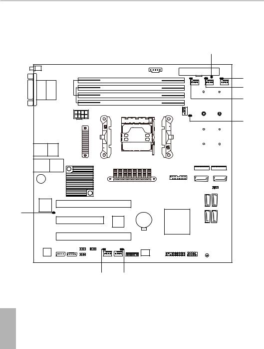
1 |
SB_PWR1 |
Green |
STB PWR ready |
2 |
FAN_LED4 |
Amber |
FAN4 failed |
3 |
FAN_LED3 |
Amber |
FAN3 failed |
4 |
FAN_LED2 |
Amber |
FAN2 failed |
5 |
FAN_LED1 |
Amber |
FAN1(CPU) failed |
6 |
FAN_LED5 |
Amber |
FAN5 failed |
7 |
FAN_LED6 |
Amber |
FAN6 failed |
8 |
BMC_LED1 |
Green |
BMC heartbeat LED |
English
9
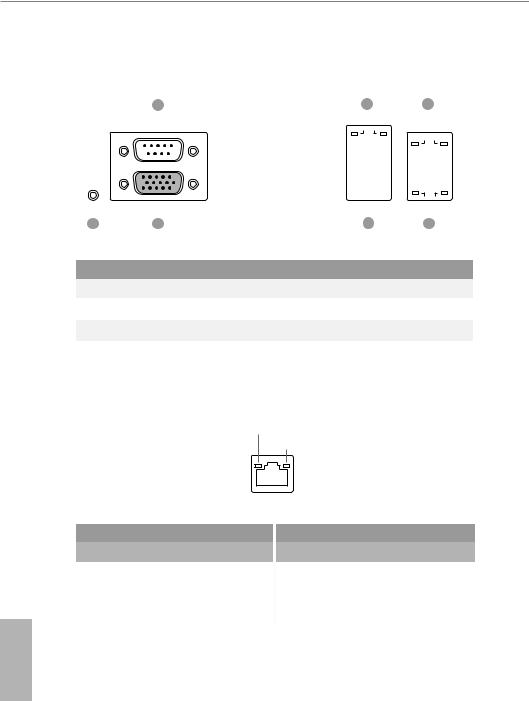
1.6 I/O Panel
|
3 |
|
5 |
|
|
|
|
7 |
|
|
|
|
||||||||
|
|
|
|
|
|
|
|
|
|
|
|
|
|
|
|
|
|
|
|
|
|
|
|
|
|
|
|
|
|
|
|
|
|
|
|
|
|
|
|
|
|
|
|
|
|
|
|
|
|
|
|
|
|
|
|
|
|
|
|
|
|
|
|
|
|
|
|
|
|
|
|
|
|
|
|
|
|
|
|
|
|
|
|
|
|
|
|
|
|
|
|
|
|
|
|
|
|
|
|
|
|
|
|
|
|
|
|
|
|
|
|
|
|
|
|
|
|
|
|
|
|
|
|
|
|
|
|
|
|
|
|
|
|
|
|
|
|
|
|
|
|
|
|
|
|
|
|
|
|
|
|
|
|
|
|
|
|
|
|
|
|
|
|
|
|
|
|
|
|
|
|
|
|
|
|
|
|
|
|
|
|
|
|
|
|
|
|
|
|
|
|
|
|
|
|
|
|
|
|
|
|
|
|
|
|
|
|
|
|
|
|
|
|
|
|
|
|
|
|
|
|
|
|
|
|
|
|
|
|
|
1 |
2 |
|
|
4 |
6 |
No. |
Description |
|
No. |
Description |
|
|
|
||||
1 |
UID Switch (UID1) |
|
5 |
LAN RJ-45 Port (IPMI_LAN1)* |
|
2 |
VGA Port (VGA1) |
|
6 |
10G LAN RJ-45 Port (LAN3)** |
|
3 |
Serial Port (COM1) |
|
7 |
10G LAN RJ-45 Port (LAN4)** |
|
4 |
USB 3.1 Gen1 Ports (USB3_1_2) |
|
|
|
|
|
|
|
|
|
|
*There are two LED next to the LAN port. Please refer to the table below for the LAN port LED indications.
ACT/LINK LED
SPEED LED
LAN Port
Dedicated IPMI LAN Port LED Indications
Activity / Link LED
Status |
|
Description |
Off |
|
No Link |
|
||
|
|
|
Blinking Yellow |
|
Data Activity |
On |
|
Link |
Speed LED |
|
|
Status |
|
Description |
Off |
|
10M bps connection or no |
|
||
|
|
link |
Yellow |
|
100M bps connection |
Green |
|
1Gbps connection |
English
10
X470D4U2-2T
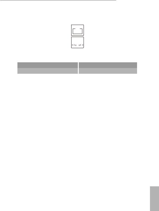
**There are two LEDs on each LAN port. Please refer to the table below for the LAN port LED indications.
ACT/LIN K LED 


 SPEED LED
|
|
ACT/LIN K LED |
|
|
|
|
|
|
|
|
|
|
|
|
|
SPEED LED |
|
|
|
|
|
|
|
|
|
|
|
|
|
|
|
|
|
|
|
||
|
|
|
|
|
LAN Port |
|
|
|||||||||||
10G LAN Port (LAN3, LAN4) LED Indications |
|
|
||||||||||||||||
Activity / Link LED |
|
|
|
|
|
|
Speed LED |
|
|
|||||||||
Status |
|
Description |
|
|
|
|
|
|
Status |
|
Description |
|||||||
Off |
|
No Link |
|
|
|
|
|
|
Off |
|
10M/100Mbps |
|||||||
|
|
|
|
|
|
|
|
|||||||||||
|
|
|
|
|
|
|
|
|
|
|
|
|
|
|
|
|
|
connection or no link |
Blinking Yellow |
|
Data Activity |
|
|
|
|
|
|
Orange |
|
1Gbps connection |
|||||||
On |
|
Link |
|
|
|
|
|
|
Green |
|
10Gbps connection |
|||||||
English
11
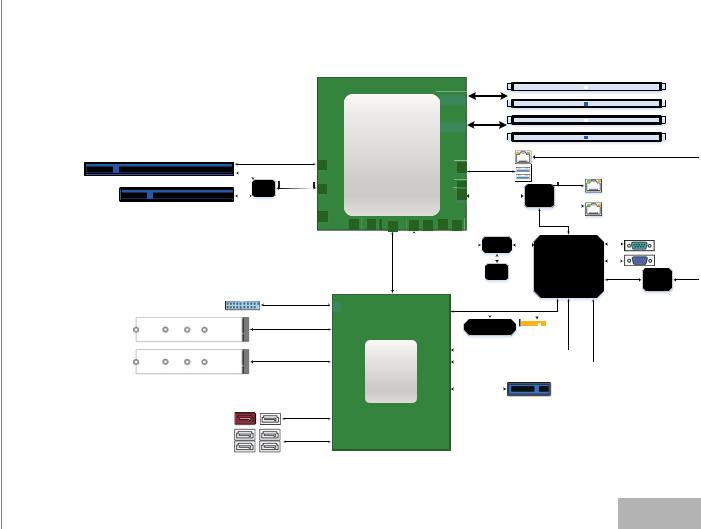
1.7 Block Diagram
|
|
A |
|
|
|
|
|
|
|
|
|
|
|
|
|
|
|
|
|
||
|
|
|
|
|
|
|
|
|
|
|
|
|
|
|
|
|
|
|
|
||
AMD Ryzen™ |
DDR4 |
|
|
|
|
|
|
|
|
|
B |
|
|
|
|
|
|
|
|
||
|
|
|
|
|
|
|
|
|
||
nd2 Generation |
|
|
|
|
|
|
|
|
|
|
DDR4 |
|
|
|
|
|
|
|
|
||
|
|
|
|
|
|
|
|
|||
|
|
|
|
|
|
|
||||
|
|
|
|
|
|
|
|
|
||
Processor |
|
|
|
|
|
|
|
|
|
|
|
|
|
|
|
|
|
|
|
|
|
|
|
|
|
|
|
|
|
|
|
|
|
PCIe3.0x8 |
AMD AM4 Socket |
|
IPMI |
|
SLOT6 x16 |
2xUSB3.0, |
|
|
||
|
PGA 1331 |
|
|
||
|
|
2xUSB2.0 |
|
10GbE |
|
|
MUX PCIe3.0x8 |
|
|
||
SLOT4 x8 |
|
PCIe3.0x4 |
X550 |
||
TDP: max. 105W |
|
||||
|
|
|
-AT2 |
10GbE |
|
|
|
|
|
||
NCSI
|
|
|
Switch |
|
|
|
|
|
|
|
|
|
|
|
|
COM port |
|
|
|
|
|
SPI |
|
|
|
|
|
|
|
||||
|
|
|
|
|
|
|
|
|
|
|
|
|
|
|
|
D-Sub |
|
|
|
|
|
|
|
|
|
|
|
|
|
VGA |
|
|
|
|
|
|
|
|
|
|
|
|
|
|
|
|
|
|
|
|
|
|
|
BIOS |
|
|
|
|
|
|
|
|
|
|
RGMII |
8211E |
|
|
|
|
|
|
|
|
|
|
|
|
|
|
|
|
||
|
|
|
|
|
|
|
|
|
|
|
|
|
|
|
||
2xUSB3.0, |
|
|
|
|
|
|
LPC |
USB |
|
PCIe |
|
|
|
|||
|
|
|
|
|
|
|
|
|
|
|
|
|
|
|
|
|
2xUSB2.0 |
|
|
|
|
|
|
|
|
|
|
|
|
|
|
|
|
|
|
|
|
|
|
|
|
|
|
|
|
|
|
|
|
|
PCIe2.0 x4 |
|
|
|
|
|
|
|
|
|
|
|
|
|
|
|
|
|
|
|
|
|
|
|
|
|
|
|
|
|
|
|
|
|
|
|
|
|
|
|
|
|
|
|
|
|
|
|
|
|
|
PCIe3.0 x2/SATAIII |
|
AMD |
PCIe2.0 x1 |
|
|
|
|
|
|
|
|
|
|
|
|
|
|
|
|
|
|
|
|
|
|
|
|
|
|
|
|
|
|
|
|
470X |
PCIe2.0x1 |
SLOT5 x1 |
|
|
|
|
||||||||
|
|
|
|
|
|
|
||||||||||
2x SATAIII
4x SATAIII
12
English
X470D4U2-2T
Chapter 2 Installation
This is a micro-ATX form factor (9.6” x 9.6”, 24.4 cm x 24.4 cm) motherboard. Before you install the motherboard, study the configuration of your chassis to ensure that the motherboard fits into it.
Make sure to unplug the power cord before installing or removing the motherboard. Failure to do so may cause physical injuries to you and damages to motherboard components.
2.1 Screw Holes
Place screws into the holes indicated by circles to secure the motherboard to the chassis.
Attention! Before installing this motherboard, be sure to unscrew and remove the standoffs at the marked location, under the motherboard, from the chassis, in order to avoid electrical short circuit and damage to your motherboard.
Do not over-tighten the screws! Doing so may damage the motherboard.
2.2 Pre-installation Precautions
Take note of the following precautions before you install motherboard components or change any motherboard settings.
1.Unplug the power cord from the wall socket before touching any components.
2.To avoid damaging the motherboard’s components due to static electricity, NEVER place your motherboard directly on the carpet or the like. Also remember to use a grounded wrist strap or touch a safety grounded object before you handle the components.
3.Hold components by the edges and do not touch the ICs.
4.Whenever you uninstall any component, place it on a grounded anti-static pad or in the bag that comes with the component.
5.When placing screws into the screw holes to secure the motherboard to the chassis, please do not over-tighten the screws! Doing so may damage the motherboard.
Before you install or remove any component, ensure that the power is switched off or the power cord is detached from the power supply. Failure to do so may cause severe damage to the motherboard, peripherals, and/or components.
English
13
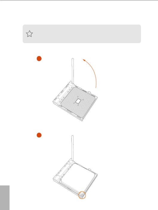
2.3 Installing the CPU
Unplug all power cables before installing the CPU.
1
2
English
14
X470D4U2-2T
3
English
15
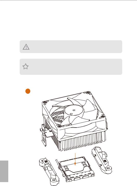
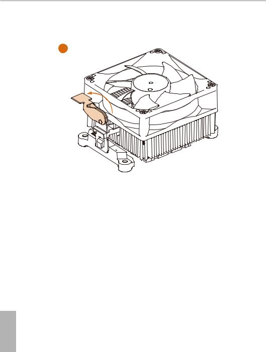
2.4 Installing the CPU Fan and Heatsink
After you install the CPU into this motherboard, it is necessary to install a larger heatsink and cooling fan to dissipate heat. You also need to spray thermal grease between the CPU and the heatsink to improve heat dissipation. Make sure that the CPU and the heatsink are securely fastened and in good contact with each other.
Please be aware of the maximum dimensions of the heatsink to be used is 116 * 83.65mm.
Please turn off the power or remove the power cord before changing a CPU or heatsink.
Installing the CPU Box Cooler SR1
1
English
16

X470D4U2-2T
2
3
English
17
4
English
18
Loading...