


 Loading...
Allied Telesis AT-MMC2000LX-LC, AT-MMC2000-SC, AT-MMC2000LX-SC, AT-MMC200LX-SC, AT-MMC200LX-ST User Manual
...
MMC2000/200 Series
Mini Switching Media Converters
AT-MMC2000/SC
AT-MMC2000/ST
AT-MMC2000/LC
AT-MMC2000/SP
AT-MMC2000LX/SC
AT-MMC2000LX/LC
AT-MMC200/SC
AT-MMC200/ST
AT-MMC200/LC
AT-MMC200LX/SC
AT-MMC200LX/ST
Installation Guide
613-002037 Rev. D
Copyright 2018 Allied Telesis, Inc.
All rights reserved. No part of this publication may be reproduced without prior written permission from Allied Telesis, Inc.
Allied Telesis and the Allied Telesis logo are trademarks of Allied Telesis, Incorporated. All other product names, company names, logos or other designations mentioned herein are trademarks or registered trademarks of their respective owners.
Allied Telesis, Inc. reserves the right to make changes in specifications and other information contained in this document without prior written notice. The information provided herein is subject to change without notice. In no event shall Allied Telesis, Inc. be liable for any incidental, special, indirect, or consequential damages whatsoever, including but not limited to lost profits, arising out of or related to this manual or the information contained herein, even if Allied Telesis, Inc. has been advised of, known, or should have known, the possibility of such damages.

Electrical Safety and Emissions
Standards
This section contains the following:
“US Federal Communications Commission”
“Industry Canada”
“Emissions, Immunity and Electrical Safety Standards” on page 4
“Translated Safety Statements” on page 4
US Federal Communications Commission
Radiated Energy
Note
This equipment has been tested and found to comply with the limits for a Class A digital device pursuant to Part 15 of FCC Rules. These limits are designed to provide reasonable protection against harmful interference when the equipment is operated in a commercial environment.
This equipment generates, uses, and can radiate radio frequency energy and, if not installed and used in accordance with this instruction manual, may cause harmful interference to radio communications. Operation of this equipment in a residential area is likely to cause harmful interference in which case the user will be required to correct the interference at his own expense.
Note
Modifications or changes not expressly approved of by the manufacturer or the FCC, can void your right to operate this equipment.
Industry Canada
Radiated Energy
This Class A digital apparatus complies with Canadian ICES-003.
Cet appareil numérique de la classe A est conforme à la norme NMB-003 du Canada.
3

Emissions, Immunity and Electrical Safety Standards
RFI Emissions FCC Class A, EN55022 Class A, CISPR 22 Class A, VCCI Class A, RCM
Warning
In a domestic environment this product may cause radio interference in which case the user may be required to take adequate measures. E84
EMC (Immunity) |
EN55024, EN61000-3-2, EN61000-3-3 |
Electrical Safety |
EN60950-1 (TUV), UL 60950-1 (CULUS) |
Warning
Laser Safety: EN60825 L7
Translated Safety Statements
Important: The indicates that a translation of the safety statement is available in a PDF document titled Translated Safety Statements on the Allied Telesis website at www.alliedtelesis.com/support.
4

Contents
Preface............................................................................................................................................................. |
11 |
Symbol Conventions .................................................................................................................................. |
12 |
Contacting Allied Telesis............................................................................................................................ |
13 |
Chapter 1: Overview ..................................................................................................................................... |
15 |
Introduction ................................................................................................................................................ |
16 |
Features .............................................................................................................................................. |
16 |
Twisted-Pair Port ................................................................................................................................. |
18 |
Auto MDI/MDI-X .................................................................................................................................. |
18 |
Auto-Negotiation or 100 Mbps Full-Duplex Mode................................................................................ |
18 |
LEDs.................................................................................................................................................... |
19 |
Smart MissingLink™ (SML)................................................................................................................. |
21 |
SML Example Scenarios............................................................................................................... |
21 |
SML Example Scenarios with Two Connected Media Converters................................................ |
22 |
Enabling SML................................................................................................................................ |
23 |
External AC/DC Power Adapter .......................................................................................................... |
23 |
Front and Back Panels............................................................................................................................... |
25 |
Reset the Media Converter ........................................................................................................................ |
28 |
Chapter 2: Installation ................................................................................................................................... |
29 |
Reviewing Safety Precautions ................................................................................................................... |
30 |
Selecting a Site for the Media Converter ................................................................................................... |
32 |
Planning the Installation............................................................................................................................. |
33 |
Unpacking the Media Converter................................................................................................................. |
37 |
Installing the Media Converter ................................................................................................................... |
40 |
Installing the Media Converter on a Desktop....................................................................................... |
40 |
Installing the SFP Transceiver ................................................................................................................... |
41 |
Powering On and Cabling the Media Converter......................................................................................... |
44 |
Cabling Guidelines .............................................................................................................................. |
44 |
Applying Power and Connecting the Network Cables ......................................................................... |
44 |
Chapter 3: Troubleshooting .......................................................................................................................... |
47 |
Appendix A: Technical Specifications ............................................................................................................ |
51 |
Physical Specifications............................................................................................................................... |
51 |
Environmental Specifications ..................................................................................................................... |
51 |
Power Specifications.................................................................................................................................. |
52 |
Safety and Electromagnetic Emissions Certifications ................................................................................ |
52 |
RJ45 Connector and Port Pinouts.............................................................................................................. |
52 |
Fiber-Optic Port Specifications................................................................................................................... |
54 |
Appendix B: Cleaning Fiber-Optic Connectors .............................................................................................. |
57 |
Introduction ................................................................................................................................................ |
57 |
Using a Cartridge-Type Cleaner ................................................................................................................ |
58 |
Using a Swab............................................................................................................................................. |
60 |
Appendix C: AT-MMCWLMT Kit Installation .................................................................................................. |
63 |
5
Contents
6

Figures
Figure 1: PWR and SYS LEDs ............................................................................................................................................ |
19 |
Figure 2: Port LEDs ............................................................................................................................................................. |
19 |
Figure 3: SML in Normal Condition...................................................................................................................................... |
21 |
Figure 4: SML with Fiber Connection Down ........................................................................................................................ |
21 |
Figure 5: SML with Copper Connection Down..................................................................................................................... |
22 |
Figure 6: SML in Normal Condition with Two Media Converters......................................................................................... |
22 |
Figure 7: SML with Copper Connection to End Node Down................................................................................................ |
22 |
Figure 8: SML with Fiber Connection Between Media Converters Down............................................................................ |
23 |
Figure 9: MMC2000/200 Series Converter Rear Panel DIP Switches................................................................................. |
23 |
Figure 10: MMC2000/200/SC Series and MMC2000/200/LX/SC Series Front Panel......................................................... |
25 |
Figure 11: MMC2000/200/ST Series and AT-MMC200/LX/ST Front Panel ........................................................................ |
25 |
Figure 12: MMC2000/200LC Series and AT-MMC2000/LX/LC Front Panel ....................................................................... |
26 |
Figure 13: AT-MMC2000/SP Front Panel............................................................................................................................ |
26 |
Figure 14: Media Converter Back Panel.............................................................................................................................. |
27 |
Figure 15: MMC2000/200/SC Series and MMC2000/200/LX/SC Series Shipping Package Contents ............................... |
37 |
Figure 16: MMC2000/200/ST Series and AT-MMC200LX/ST Shipping Package Contents ............................................... |
38 |
Figure 17: MMC2000/200/LC Series and AT-MMC2000/LX/LC Shipping Package Contents ............................................ |
38 |
Figure 18: AT-MMC2000/SP Shipping Package Contents.................................................................................................. |
39 |
Figure 19: Removing the Dust Plug from an SFP Slot ........................................................................................................ |
41 |
Figure 20: Inserting the SFP................................................................................................................................................ |
42 |
Figure 21: Positioning the SFP Handle in the Upright Position ........................................................................................... |
42 |
Figure 22: Connecting 12VDC Powered Unit ...................................................................................................................... |
44 |
Figure 23: RJ45 Connector and Port Pin Layout................................................................................................................. |
52 |
Figure 24: Ferrule in an SC Connector Plug........................................................................................................................ |
57 |
Figure 25: Unclean and Clean Ferrule................................................................................................................................. |
58 |
Figure 26: Cartridge Cleaner ............................................................................................................................................... |
58 |
Figure 27: Rubbing the Ferrule Tip on the Cleaning Surface .............................................................................................. |
59 |
Figure 28: Lint-Free and Alcohol-Free Swabs..................................................................................................................... |
60 |
Figure 29: Cleaning a Recessed Ferrule............................................................................................................................. |
61 |
Figure 30: Attaching the Brackets to the Media Converter.................................................................................................. |
64 |
Figure 31: Wall-mount Template ......................................................................................................................................... |
64 |
Figure 32: Placing the Template on the Wall....................................................................................................................... |
65 |
Figure 33: Securing the Media Converter to the Wall.......................................................................................................... |
66 |
7
List of Figures
8

Tables
Table 1. Connecting Networks ............................................................................................................................................ |
16 |
|
Table 2. |
Media Converter LED Functional Descriptions ..................................................................................................... |
20 |
Table 3. |
Twisted-Pair Port Cabling Specifications .............................................................................................................. |
34 |
Table 4. Copper Connection Speed/Duplex Settings and Resulting Speed - MMC2000 ................................................... |
34 |
|
Table 5. Copper Connection Speed/Duplex Settings and Resulting Speed - AT-MMC200 ............................................... |
36 |
|
Table 6. |
Physical Specifications ......................................................................................................................................... |
51 |
Table 7. |
Environmental Specifications ................................................................................................................................ |
51 |
Table 8. |
Power Specifications ............................................................................................................................................ |
52 |
Table 9. |
Safety and Electromagnetic Emissions Certifications ........................................................................................... |
52 |
Table 10. MDI Pin Signals (10 or 100 Mbps) ...................................................................................................................... |
53 |
|
Table 11. MDI-X Pin Signals (10 or 100 Mbps) .................................................................................................................. |
53 |
|
Table 12. |
Pin Signals (1000 Mbps) ..................................................................................................................................... |
53 |
Table 13. |
Fiber Type .......................................................................................................................................................... |
54 |
Table 14. |
AT-MMC2000 Fiber-Optic Port Specifications .................................................................................................... |
54 |
Table 15. |
AT-MMC200 Fiber-Optic Port Specifications ...................................................................................................... |
55 |
Table 16. |
AT-MMC2000LX Fiber-Optic Port Specifications ............................................................................................... |
55 |
Table 17. |
AT-MMC200LX Fiber-Optic Port Specifications ................................................................................................. |
55 |
Table 18. AT-MMCR WLMT Kit Contents ........................................................................................................................... |
63 |
|
9
List of Tables
10
Preface
This preface contains the following sections:
“Symbol Conventions” on page 12
“Contacting Allied Telesis” on page 13
This guide contains the installation instructions for the following Mini Switching Media Converters.
AT-MMC2000/SC
AT-MMC2000/ST
AT-MMC2000/SP
AT-MMC2000/LC
AT-MMC2000LX/LC
AT-MMC2000LX/SC
AT-MMC200/SC
AT-MMC200/ST
AT-MMC200/LC
AT-MMC200LX/SC
AT-MMC200LX/ST
11

Symbol Conventions
This document uses the following conventions:
Note
Notes provide additional information.
Caution
Cautions inform you that performing or omitting a specific action may result in equipment damage or loss of data.
Warning
Warnings inform you that performing or omitting a specific action may result in bodily injury.
Warning
Laser warnings inform you that an eye and skin hazard exists due to the presence of a Class 1 laser device.
12

MMC2000/200 Series Mini Switching Media Converter Installation Guide
Contacting Allied Telesis
If you need assistance with this product, you may contact Allied Telesis technical support by going to the Support & Services section of the Allied Telesis web site at www.alliedtelesis.com/support. You can find links for the following services on this page:
24/7 Online Support - Enter our interactive support center to search for answers to your questions in our knowledge database, check support tickets, learn about Return Merchandise Authorizations (RMAs), and contact Allied Telesis technical experts.
USA and EMEA phone support - Select the phone number that best fits your location and customer type.
Hardware warranty information - Learn about Allied Telesis warranties and register your product online.
Replacement Services - Submit an RMA request via our interactive support center.
Documentation - View the most recent installation guides, user guides, software release notes, white papers and data sheets for your product.
Software Updates - Download the latest software releases for your product.
For sales or corporate contact information, select your region and country, then go to www.alliedtelesis.com/contact.
13
14

Chapter 1
Overview
This chapter contains the following sections:
“Introduction” on page 16
“Front and Back Panels” on page 25
“Reset the Media Converter” on page 28
15

Chapter 1: Overview
Introduction
The MMC2000/200 Series Mini Switching Media Converters are designed to extend the distance of your network by interconnecting LAN devices that are physically separated by large distances.
The MMC2000/200 Series Mini Switching Media Converters include the following models:
AT-MMC2000/SC
AT-MMC2000/ST
AT-MMC2000/SP
AT-MMC2000/LC
AT-MMC2000LX/LC
AT-MMC2000LX/SC
AT-MMC200/SC
AT-MMC200/ST
AT-MMC200/LC
AT-MMC200LX/SC
AT-MMC200LX/ST
Features Here are the key features of the MMC2000/200 Series converters:
The media converter provides a smaller-sized space-saving alternative that allows enterprises to connect copper networks to fiber networks, offering a cost-effective method for integrating fiber-optic cabling into a 10/100/1000 or 10/100 UTP environment. See Table 1 for the specifications of the ports that the media converter is equipped with.
Table 1. Connecting Networks
Models |
Fiber-optic Port |
Copper Port |
||
|
|
|||
Connector |
L1 Standard |
|||
|
|
|||
|
|
|
|
|
|
|
|
|
|
AT-MMC2000/LC |
LC |
|
|
|
|
|
|
|
|
AT-MMC2000/SC |
SC |
1000Base-SX |
|
|
|
|
|
|
|
AT-MMC2000/ST |
ST |
|
10/100/1000Base-T |
|
|
|
|
|
|
AT-MMC2000LX/LC |
LC |
1000Base-LX |
|
|
|
|
|
||
AT-MMC2000LX/SC |
SC |
|
||
|
|
|||
|
|
|
|
|
16

MMC2000/200 Series Mini Switching Media Converter Installation Guide
Table 1. Connecting Networks (Continued)
Models |
Fiber-optic Port |
Copper Port |
||
|
|
|||
Connector |
L1 Standard |
|||
|
|
|||
|
|
|
|
|
|
|
|
|
|
AT-MMC2000/SP |
SFP slot |
100/1000Base-X |
10/100/1000Base-T |
|
|
|
|
|
|
AT-MMC200/LC |
LC |
|
|
|
|
|
|
|
|
AT-MMC200/SC |
SC |
100Base-FX |
|
|
|
|
|
|
|
AT-MMC200/ST |
ST |
|
10/100Base-TX |
|
|
|
|
|
|
AT-MMC200LX/SC |
SC |
100Base-LX |
|
|
|
|
|
||
AT-MMC200LX/ST |
ST |
|
||
|
|
|||
|
|
|
|
|
Smart MissingLink™ (SML)
Auto Negotiation and Auto MDI/MDI-X on the twisted-pair port
Wall-moun
Support for Jumbo frames up to 10kB
LEDs for unit and port status
DIP switch for activating the SML feature
DIP switch for 100 Mbps full-duplex mode or Auto-Negotiation
12 VDC external wall-mount AC power adapter
The AT-MMC2000LX/nn and AT-MMC200LX/nn models operate with a single-mode fiber optic cable.
The fiber port of the AT-MMC2000/nn model has a maximum operating distance of 500m.
The fiber port of the AT-MMC200/nn model has a maximum operating distance of 2km.
The fiber port of the AT-MMC2000/200LX/nn model has a maximum operating distance of 20km.
Note
The parameter nn can be SC, ST, SP, or LC.
Note
For more details, see “Fiber-Optic Port Specifications” on page 54.
The AT-MMC2000/SP model has a plug-in SFP cage fiber connection. 100Mbps and 1Gbps modules are supported.
17

Chapter 1: Overview
Twisted-Pair Port
Auto MDI/
MDI-X
Auto-Negotiation or 100 Mbps FullDuplex Mode
Note
For the AT-MMC2000/SP model, you must purchase the SFP transceiver separately. The maximum operating distance of the ATMMC2000/SP is dependent on the specific SFP module. For a list of supported transceivers, contact your Allied Telesis distributor or reseller.
Here are the basic features of the twisted-pair (copper) port:
IEEE 802.3u Auto-Negotiation compliant
Auto MDI/MDI-X
100 meters (328 feet) maximum operating distance
RJ45 connector
The twisted-pair port features an eight-pin RJ45 connector that uses four pins at 10 or 100 Mbps and all eight pins at 1000 Mbps. For the port pinouts, see “RJ45 Connector and Port Pinouts” on page 52.
Note
For twisted-pair port cabling specifications, refer to Table 3 on page 34.
An RJ45 twisted-pair port on a 100 Mbps Ethernet network device can have one of two possible wiring configurations: MDI or MDI-X. The RJ45 port on a PC, router, or bridge is typically wired as MDI, while the twistedpair port on a switch or hub is usually MDI-X.
The media converter features Auto MDI/MDI-X. The twisted-pair port automatically determines the configuration of the port on the device to which it is connected and then configures itself appropriately.
For example, if a port on a media converter is connected to a port on a bridge, which is typically wired as MDI, the port on the media converter automatically configures itself as MDI-X.
This feature allows you to use a straight-through cable when connecting any type of device to the media converter, regardless of the wiring configuration of the port on the device.
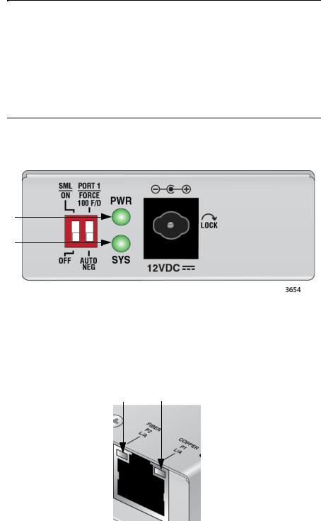
You can set the twisted-pair port to 100 Mbps full-duplex mode or AutoNegotiation mode using the PORT 1 (right) DIP switch on the rear panel. See Figure 9 on page 23.
When this DIP switch is in the FORCE 100 F/D (up) position, the twisted-pair port is forced to 100 Mbps full-duplex mode, and Auto Negotiation is disabled.
18
MMC2000/200 Series Mini Switching Media Converter Installation Guide
When in the AUTO NEG (down) position, the twisted-pair port operates in Auto-Negotiation mode.
Note
100 Mbps full-duplex mode should not be used unless absolutely necessary because forcing 100 Mbps full-duplex in most applications is likely to cause a duplex mismatch, in turn, causing poor network performance. 100 Mbps full-duplex mode should only be used when the link partner is already forced to 100 Mbps fullduplex operation, and Auto Negotiation is disabled on the link partner. In this specific case, using Auto Negotiation on the media converter would result in a duplex mismatch.
LEDs Figure 1 shows the PWR and SYS LEDs.
PWR
SYS
Figure 1. PWR and SYS LEDs
Figure 2 shows the port LEDs.
FIBER |
COPPER |
P2 |
P1 |
L/A |
L/A |
Figure 2. Port LEDs
19
Chapter 1: Overview
Table 2 describes the media converter’s LEDs.
Table 2. Media Converter LED Functional Descriptions
LED |
State |
|
Description |
|
|
|
|
|
|
|
|
|
|
|
PWR |
Off |
The media converter is not receiving power. |
|
|
|
|
|
|
|
Steady Green |
The media converter is receiving power. |
|
||
|
|
|||
|
|
|
|
|
|
Off |
The media converter is not operational and |
|
|
|
|
will not pass traffic. |
|
|
|
|
|
|
|
|
Solid Green |
The media converter is operational. |
|
|
|
(with |
|
|
|
|
Heartbeat) |
|
Note |
|
SYS |
|
|
The SYS LED will flicker briefly at a |
|
|
|
|
regular interval. This “heartbeat” |
|
|
|
|
indicates that the internal system is |
|
|
|
|
running normally. |
|
|
|
|
|
|
|
|
|
|
|
|
Slow Blinking |
An error is present on the media converter. |
|
|
|
Green |
|
|
|
|
|
|
|
|
|
Off |
The port has not established a link. |
|
|
|
|
|
|
|
|
Steady Green |
The port has an established link to a network |
|
|
COPPER |
|
device, but it is not transmitting or receiving |
|
|
|
network packets. |
|
||
P1 L/A |
|
|
||
(L = Link; |
Rapid Blinking |
The port is transmitting or receiving network |
|
|
A = Activity) |
|
|||
|
Green |
packets. |
|
|
|
Slow Blinking |
SML is on and detects a failure on the fiber |
|
|
|
Green |
port. |
|
|
|
|
|
|
|
|
Off |
The port has not established a link. |
|
|
|
|
|
|
|
|
Steady Green |
The port has an established link to a network |
|
|
|
|
device, but it is not transmitting or receiving |
|
|
FIBER P2 |
|
network packets. |
|
|
|
|
|
|
|
Rapid Blinking |
The port is transmitting or receiving network |
|
||
L/A |
|
|||
(L = Link; |
Green |
packets. |
|
|
A = Activity) |
|
|
|
|
Slow Blinking |
SML is on and detects a failure on the copper |
|
||
|
|
|||
|
Green |
port or the remote fiber port when operating |
|
|
|
|
in a back-to-back configuration with another |
|
|
|
|
MMC2000/200 Series media converter. See |
|
|
|
|
Figure 7 on page 22. |
|
|
|
|
|
|
|
20
Loading...