


 Loading...
GS980M Series
Gigabit Ethernet Switches
AlliedWare Plus™
AT-GS980M/52
AT-GS980M/52PS
Installation Guide
613-002638 Rev. B
Copyright 2019 Allied Telesis, Inc.
All rights reserved. No part of this publication may be reproduced without prior written permission from Allied Telesis, Inc.
Allied Telesis, VCStack, and the Allied Telesis logo are trademarks of Allied Telesis, Incorporated. All other product names, company names, logos or other designations mentioned herein are trademarks or registered trademarks of their respective owners.
Allied Telesis, Inc. reserves the right to make changes in specifications and other information contained in this document without prior written notice. The information provided herein is subject to change without notice. In no event shall Allied Telesis, Inc. be liable for any incidental, special, indirect, or consequential damages whatsoever, including but not limited to lost profits, arising out of or related to this manual or the information contained herein, even if Allied Telesis, Inc. has been advised of, known, or should have known, the possibility of such damages.

Electrical Safety and Emissions Standards
This product meets the following standards.
U.S. Federal Communications Commission
Radiated Energy
Note: This equipment has been tested and found to comply with the limits for a Class A digital device pursuant to Part 15 of FCC Rules. These limits are designed to provide reasonable protection against harmful interference when the equipment is operated in a commercial environment. This equipment generates, uses, and can radiate radio frequency energy and, if not installed and used in accordance with this instruction manual, may cause harmful interference to radio communications. Operation of this equipment in a residential area is likely to cause harmful interference in which case the user will be required to correct the interference at his own expense.
Note: Modifications or changes not expressly approved of by the manufacturer or the FCC, can void your right to operate this equipment.
Industry Canada
This Class A digital apparatus complies with Canadian ICES-003.
Cet appareil numérique de la classe A est conforme à la norme NMB-003 du Canada.
Warning: In a domestic environment this product may cause radio interference in which case the user may be required to take adequate measures.
EMC |
|
EN 55024 |
|
|
EN 55032 Class A |
|
|
EN 61000-3-2 |
|
|
EN 61000-3-3 |
|
|
FCC Part 15 (CFR 47) Class A |
|
|
VCCI Class A |
|
|
CISPR 22 Class A |
|
|
ICES-003 |
|
|
|
Environmental Compliance |
RoHS |
|
|
|
WEEE |
|
|
|
Electrical Safety |
|
EN 60950-1 (second edition) |
|
|
CAN/CSA-C22.2 No. 60950-1-07 (second edition) |
|
|
UL 60950-1 (second edition) |
|
|
cULus Mark |
|
|
TUV-T-Mark |
|
|
|
Regulatory Compliance |
|
RCM |
|
|
CE |
|
|
|
Laser Safety |
EN60825 |
|
3

Translated Safety Statements
Important: Safety statements that have the symbol are translated into multiple languages in the
Translated Safety Statements document at www.alliedtelesis.com/library.
Remarque: Les consignes de sécurité portant le symbole sont traduites dans plusieurs langues dans le document Translated Safety Statements, disponible à l'adresse www.alliedtelesis.com/ library
4

Contents
Preface ............................................................................................................................................................................... |
11 |
Document Conventions ....................................................................................................................................................... |
12 |
Contacting Allied Telesis ..................................................................................................................................................... |
13 |
Chapter 1: Overview ........................................................................................................................................................ |
15 |
Front and Rear Panels ........................................................................................................................................................ |
16 |
Management Panel ............................................................................................................................................................. |
18 |
Features .............................................................................................................................................................................. |
19 |
GS980M Models........................................................................................................................................................... |
19 |
10/100/1000Mbps Twisted Pair Ports .......................................................................................................................... |
19 |
100Mbps or 1Gbps SFP Transceiver Ports.................................................................................................................. |
19 |
Power Over Ethernet.................................................................................................................................................... |
20 |
LEDs............................................................................................................................................................................. |
20 |
Installation Options....................................................................................................................................................... |
20 |
Management Software and Interfaces ......................................................................................................................... |
20 |
Console Port................................................................................................................................................................. |
20 |
USB Port ...................................................................................................................................................................... |
21 |
Management Methods.................................................................................................................................................. |
21 |
Power Conservation ..................................................................................................................................................... |
21 |
MAC Address Table ..................................................................................................................................................... |
21 |
10/100/1000Mbps Twisted Pair Ports.................................................................................................................................. |
22 |
Connector Type............................................................................................................................................................ |
22 |
Speed ........................................................................................................................................................................... |
22 |
Duplex Mode ................................................................................................................................................................ |
22 |
Maximum Distance....................................................................................................................................................... |
22 |
Cable Requirements..................................................................................................................................................... |
22 |
Automatic MDIX Detection ........................................................................................................................................... |
23 |
LEDs............................................................................................................................................................................. |
23 |
Power Over Ethernet on the AT-GS980M/52PS Switch...................................................................................................... |
26 |
PoE Standards ............................................................................................................................................................. |
26 |
Powered Device Classes ............................................................................................................................................. |
26 |
Power Budget............................................................................................................................................................... |
27 |
Port Priorities................................................................................................................................................................ |
27 |
Wiring Implementation.................................................................................................................................................. |
28 |
SFP Transceiver Ports......................................................................................................................................................... |
29 |
SFP Transceivers......................................................................................................................................................... |
29 |
LEDs............................................................................................................................................................................. |
29 |
Fault and Power LEDs......................................................................................................................................................... |
31 |
eco-friendly Button............................................................................................................................................................... |
32 |
USB Port.............................................................................................................................................................................. |
33 |
USB Port LED .............................................................................................................................................................. |
33 |
Console Port........................................................................................................................................................................ |
34 |
Power Supply and Fan ........................................................................................................................................................ |
35 |
Specifying Ports in the Command Line Interface................................................................................................................. |
36 |
Chapter 2: Beginning the Installation ............................................................................................................................ |
37 |
Reviewing Safety Precautions............................................................................................................................................. |
38 |
Installation Options .............................................................................................................................................................. |
42 |
Choosing a Site for the Switch ............................................................................................................................................ |
43 |
Unpacking the Switch .......................................................................................................................................................... |
44 |
5
Contents |
|
Chapter 3: Installing the Switch on a Table or Desktop ............................................................................................... |
47 |
Chapter 4: Installing the Switch in an Equipment Rack ............................................................................................... |
51 |
Beginning the Installation.................................................................................................................................................... |
52 |
Required Items ............................................................................................................................................................ |
52 |
Switch Orientations in the Equipment Rack................................................................................................................. |
52 |
Removing the Bumper Feet................................................................................................................................................ |
54 |
Installing the Switch ............................................................................................................................................................ |
55 |
Chapter 5: Installing the Switch on a Wall ..................................................................................................................... |
57 |
Switch Orientations on a Wall............................................................................................................................................. |
58 |
Installation Guidelines......................................................................................................................................................... |
59 |
Tools and Material ....................................................................................................................................................... |
59 |
Plywood Base ..................................................................................................................................................................... |
61 |
Installing a Plywood Base................................................................................................................................................... |
63 |
Installing the Switch on a Plywood Base ............................................................................................................................ |
64 |
Installing the Switch on a Concrete Wall............................................................................................................................. |
66 |
Chapter 6: Cabling the Networking Ports and Powering On the Switch .................................................................... |
69 |
Cabling Twisted Pair Ports.................................................................................................................................................. |
70 |
Guidelines to Handling SFP Transceivers .......................................................................................................................... |
71 |
Installing SFP Transceivers ................................................................................................................................................ |
72 |
Powering On the Switch...................................................................................................................................................... |
76 |
Starting a Local Management Session ............................................................................................................................... |
79 |
Verifying the Switch with AlliedWare Plus Commands ....................................................................................................... |
81 |
Chapter 7: Troubleshooting ............................................................................................................................................ |
83 |
Appendix A: Technical Specifications ........................................................................................................................... |
87 |
Physical Specifications ....................................................................................................................................................... |
88 |
Environmental Specifications.............................................................................................................................................. |
89 |
Power Specifications........................................................................................................................................................... |
90 |
Certificates.......................................................................................................................................................................... |
91 |
RJ-45 Twisted Pair Port Pinouts......................................................................................................................................... |
92 |
RJ-45 Style Serial Console Port Pinouts ............................................................................................................................ |
94 |
6

Figures
Figure 1: Front Panels of the GS980M Series Switches ...................................................................................................... |
16 |
Figure 2: Back Panels .......................................................................................................................................................... |
17 |
Figure 3: Management Panel ............................................................................................................................................... |
18 |
Figure 4: LEDs for the Twisted Pair Ports on the AT-GS980M/52 Switch............................................................................ |
23 |
Figure 5: LEDs for the Twisted Pair Ports on the AT-GS980M/52PS Switch....................................................................... |
24 |
Figure 6: SFP Transceiver Port LEDs .................................................................................................................................. |
29 |
Figure 7: Fault and Power LEDs........................................................................................................................................... |
31 |
Figure 8: eco-friendly Button ................................................................................................................................................ |
32 |
Figure 9: USB Port and LED ................................................................................................................................................ |
33 |
Figure 10: PORT Parameter in the Command Line Interface............................................................................................... |
36 |
Figure 11: Installation Options.............................................................................................................................................. |
42 |
Figure 12: GS980M Switch Shipping Box............................................................................................................................. |
44 |
Figure 13: Accessory Kit Items............................................................................................................................................. |
45 |
Figure 14: Parts of the Bumper Feet .................................................................................................................................... |
47 |
Figure 15: Inset the Rivet Housing into the Bumper Foot..................................................................................................... |
48 |
Figure 16: Place the Bumper Foot on a Base Corner Hole .................................................................................................. |
48 |
Figure 17: Inserting the Rivet into the Bumper Foot............................................................................................................. |
49 |
Figure 18: Bracket Holes on the Switch................................................................................................................................ |
52 |
Figure 19: GS980M Switch Orientations in an Equipment Rack .......................................................................................... |
53 |
Figure 20: Removing the Bumper Feet................................................................................................................................. |
54 |
Figure 21: Example of Attaching the Brackets to the Switch................................................................................................ |
55 |
Figure 22: Installing the Switch in an Equipment Rack......................................................................................................... |
56 |
Figure 23: Positioning the Switch on a Wall ......................................................................................................................... |
58 |
Figure 24: Switch on a Wall with a Plywood Base................................................................................................................ |
61 |
Figure 25: Steps to Installing the Switch with a Plywood Base ............................................................................................ |
62 |
Figure 26: Bracket Positions for Installing Switch on a Wall................................................................................................. |
64 |
Figure 27: Securing the Switch to the Plywood Base........................................................................................................... |
65 |
Figure 28: Marking the Locations of the Bracket Holes on a Concrete Wall ........................................................................ |
67 |
Figure 29: Installing the Switch on a Concrete Wall ............................................................................................................. |
68 |
Figure 30: Removing the Dust Plug from an SFP Port......................................................................................................... |
72 |
Figure 31: Installing an SFP Transceiver.............................................................................................................................. |
73 |
Figure 32: Removing the Dust Cover from an SFP Transceiver .......................................................................................... |
74 |
Figure 33: Positioning the SFP Handle in the Upright Position ............................................................................................ |
74 |
Figure 34: Connecting a Fiber Optic Cable to an SFP Transceiver...................................................................................... |
75 |
Figure 35: Installing the Power Cord Retaining Clip............................................................................................................. |
76 |
Figure 36: Connecting the AC Power Cord .......................................................................................................................... |
77 |
Figure 37: Lowering the Power Cord Retaining Clip............................................................................................................. |
77 |
Figure 38: Connecting the Power Cord to an AC Power Source.......................................................................................... |
78 |
Figure 39: Connecting the Management Cable to the Console RS-232 Port....................................................................... |
79 |
Figure 40: User Exec Mode Prompt ..................................................................................................................................... |
80 |
Figure 41: Pin Layout for the RJ-45 Twisted Pair Ports (Front View)................................................................................... |
92 |
7
Figures
8

Tables
Table 1: Basic Features ....................................................................................................................................................... |
19 |
Table 2: LEDS for the Twisted Pair Ports on the AT-GS980M/52 Switch ........................................................................... |
23 |
Table 3: LEDs for the Twisted Pair Ports on the AT-GS980M/52PS Switch ....................................................................... |
25 |
Table 4: IEEE Powered Device Classes .............................................................................................................................. |
26 |
Table 5: LEDS for the SFP Transceiver Ports ..................................................................................................................... |
29 |
Table 6: Fault and Power LEDS .......................................................................................................................................... |
31 |
Table 7: USB LED ............................................................................................................................................................... |
33 |
Table 8: PORT Parameter Format ....................................................................................................................................... |
36 |
Table 9: Product Dimensions ............................................................................................................................................... |
88 |
Table 10: Product Weights .................................................................................................................................................. |
88 |
Table 11: Ventilation Requirements ..................................................................................................................................... |
88 |
Table 12: Environmental Specifications ............................................................................................................................... |
89 |
Table 13: Maximum Power Consumptions .......................................................................................................................... |
90 |
Table 14: Input Voltages ...................................................................................................................................................... |
90 |
Table 15: Heat Dissipations ................................................................................................................................................. |
90 |
Table 16: Product Certificates ............................................................................................................................................. |
91 |
Table 17: Pin Signals on the RJ-45 Twisted Pair Ports at 10 or 100Mbps ......................................................................... |
92 |
Table 18: Pin Signals on the RJ-45 Twisted Pair Ports at 1Gbps ....................................................................................... |
92 |
Table 19: Pin Signals of the RJ-45 Style Serial Console Port ............................................................................................. |
94 |
9
Tables
10
Preface
This guide contains the installation instructions for the GS980M Series of Gigabit Ethernet switches. This preface contains the following sections:
“Document Conventions” on page 12
“Contacting Allied Telesis” on page 13
11

Preface
Document Conventions
This document uses the following conventions:
Note
Notes provide additional information.
Caution
Cautions inform you that performing or omitting a specific action may result in equipment damage or loss of data.
Warning
Warnings inform you that performing or omitting a specific action may result in bodily injury.
12

GS980M Series Installation Guide
Contacting Allied Telesis
If you need assistance with this product, you can contact Allied Telesis technical support by going to the Support & Services section of the Allied Telesis web site at www.alliedtelesis.com/support. You can find links for the following services on this page:
24/7 Online Support — Enter our interactive support center to search for answers to your product questions in our knowledge database, to check support tickets, to learn about RMAs, and to contact Allied Telesis technical experts.
USA and EMEA phone support — Select the phone number that best fits your location and customer type.
Hardware warranty information — Learn about Allied Telesis warranties and register your product online.
Replacement Services — Submit a Return Merchandise Authorization (RMA) request via our interactive support center.
Documentation — View the most recent installation and user guides, software release notes, white papers, and data sheets for your products.
Software Downloads — Download the latest software releases for your managed products.
For sales or corporate information, go to www.alliedtelesis.com/contact and select your region.
13
Preface
14

Chapter 1
Overview
This chapter contains the following sections:
“Front and Rear Panels” on page 16
“Management Panel” on page 18
“Features” on page 19
“10/100/1000Mbps Twisted Pair Ports” on page 22
“Power Over Ethernet on the AT-GS980M/52PS Switch” on page 26
“SFP Transceiver Ports” on page 29
“Fault and Power LEDs” on page 31
“eco-friendly Button” on page 32
“USB Port” on page 33
“Console Port” on page 34
“Power Supply and Fan” on page 35
“Specifying Ports in the Command Line Interface” on page 36
15
Chapter 1: Overview
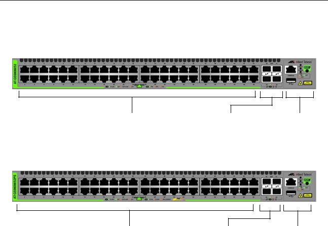
Front and Rear Panels
The front panels of the GS980M Gigabit Ethernet Switches are shown in
Figure 1.
AT-GS980M/52 Switch
48 10/100/1000Mbps Twisted |
Four 100Mbps or |
Management |
Pair Ports |
1Gbps SFP |
Panel |
|
Transceiver Ports |
|
AT-GS980M/52PS Switch |
|
|
48 10/100/1000Mbps Twisted |
Four 100Mbps or |
Management |
Pair Ports with PoE and PoE+ |
1Gbps SFP |
Panel |
|
Transceiver Ports |
|
Figure 1. Front Panels of the GS980M Series Switches
The rear panels are shown in Figure 2 on page 17.
16

GS980M Series Installation Guide
AT-GS980M/52 Switch
AC Power
Supply Connector
AT-GS980M/52PS Switch
AC Power
Supply Connector
Figure 2. Back Panels
17
Chapter 1: Overview
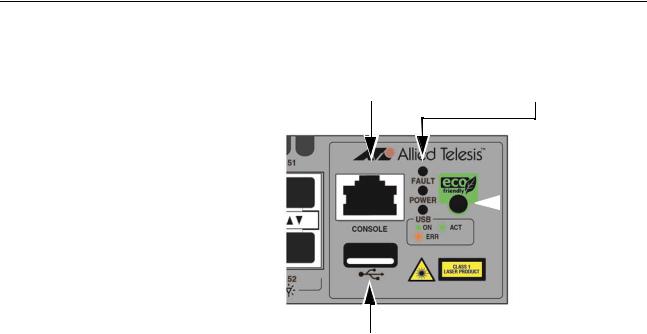
Management Panel
Figure 3 identifies the components on the management panel.
Console Management |
System LEDs |
Port |
eco-friendly  Button
USB Port
Figure 3. Management Panel
18

GS980M Series Installation Guide
Features
The following sections review the hardware features of the Gigabit
Ethernet switches in the GS980M Series.
GS980M Models Table 1 lists the basic features.
Table 1. Basic Features
|
10/100/1000 |
100Mbps or |
|
PoE Power |
|
|
1Gbps SFP |
|
|||
Model |
Mbps Twisted |
PoE and PoE+ |
|||
Transceiver |
Budget |
||||
|
Pair Ports |
|
|||
|
Ports |
|
|
||
|
|
|
|
||
|
|
|
|
|
|
AT-GS980M/52 |
48 |
4 |
No |
- |
|
|
|
|
|
|
|
AT-GS980M/52PS |
48 |
4 |
Yes |
740W |
|
|
|
|
|
|
10/100/1000Mbps Twisted Pair Ports
100Mbps or 1Gbps SFP Transceiver Ports
The switches come with one pre-installed power supply. It is not fieldreplaceable.
The forty eight twisted pair ports on the AT-GS980M/52 and AT-GS980M/ 52PS Switches have these features:
10/100/1000Mbps operation
100 meters (328 feet) maximum operating distance per port
Half or full-duplex mode
Auto-Negotiation for speed and duplex mode
Port Link/Activity (L/A) LEDs
Automatic MDIX detection at 10 or 100Mbps.
The SFP transceiver ports support the following types of transceivers:
100Mbps (100Base-FX) or 1Gbps (1000SX/LX) single-mode or multi-mode fiber optic transceivers
Single-port, BiDi fiber optic transceivers
AT-SPTX 1Gbps (1000Base-TX) transceiver with RJ-45 connector for twisted pair cable
SFP transceivers must be purchased separately. For a list of supported transceivers, refer to the product data sheet on the Allied Telesis web site.
19
Chapter 1: Overview
Power Over
Ethernet
LEDs
Installation
Options
Management
Software and
Interfaces
Console Port
Here are the basic features of PoE and PoE+ on the twisted pair ports on the AT-GS980M/52PS Switch:
Supported on all forty eight twisted pair ports
Supports PoE (15.4 watts maximum) and PoE+ (30 watts maximum) powered devices
740W power budget
Supports powered device classes 0 to 4
Mode A wiring
IEEE802.3af and IEEE802.3at compliant
Here are the port LEDs:
The SFP transceiver ports have link/activity LEDs.
The twisted pair ports on the AT-GS980M/52 Switch have speed/ activity and duplex mode LEDs.
The twisted pair ports on the AT-GS980M/52PS Switch have speed/activity and PoE status LEDs.
The management panel has system LEDs for the power supply and USB slot.
You can use the eco-friendly button to turn off the LEDs to conserve electricity.
Here are the installation options:
Desk or tabletop
Standard 19-inch equipment rack
Wood or concrete wall
Here are the management software and interfaces:
AlliedWare Plus Management Software
Command line interface
Web browser interface
The port is used for local management of the switch. A management cable is provided with the device. The port settings are provided in “Console Port” on page 34.
20
USB Port
Management
Methods
Power
Conservation
MAC Address
Table
GS980M Series Installation Guide
Here are the features and functions of the USB port:
USB 2.0 compatible
Store switch configuration files on flash drives.
Restore configuration files from flash drive to switches whose settings have been lost or corrupted, or to configure replacement units.
Update the AlliedWare Plus Management Software.
Here are the methods for managing the switches:
Local management through the Console port
Remote Telnet or Secure Shell management
Remote HTTP or HTTPS web browser management
SNMPv1, v2c, and v3
The switches have the following power conservation features:
eco-friendly button for turning off the Ethernet port LEDs to conserve electricity.
High efficiency power supply
Here are the basic features of the MAC address table:
Storage capacity of 16K MAC address entries
Automatic learning and aging
21

Chapter 1: Overview
10/100/1000Mbps Twisted Pair Ports
Connector Type
Speed
Duplex Mode
Maximum
Distance
Cable
Requirements
The following sections describe the twisted pair ports on the AT-GS980M/ 52 and AT-GS980M/52PS Switches.
The twisted pair ports have 8-pin RJ-45 connectors. The ports use four pins at 10 or 100Mbps and all eight pins at 1000Mbps. The pin assignments are listed in “RJ-45 Twisted Pair Port Pinouts” on page 92.
The ports can operate at 10, 100, or 1000Mbps. The switch can set the speeds automatically through Auto-Negotiation, the default setting, or you can manually configure them with the AlliedWare Plus Operating System.
Note
Twisted-pair ports have to be set to Auto-Negotiation to operate at 1000Mbps.
The twisted-pair ports on the switches can operate in either halfor fullduplex mode at 10 or 100Mbps. Ports operating at 1000Mbps can only operate in full-duplex mode. The twisted-pair ports are IEEE 802.3ucompliant and use Auto-Negotiate to set the duplex mode setting.
You can disable Auto-Negotiation on the ports and set the duplex mode manually.
Note
Switch ports that are connected to 10 or 100Mbps end nodes that are not using Auto-Negotiation should not use Auto-Negotiation to set their speed and duplex mode settings, because duplex mode mismatches might occur. You should disable Auto-Negotiation and set the speed and duplex mode settings manually with the AlliedWare Plus Management Software.
The ports have a maximum operating distance of 100 meters (328 feet).
The minimum cable requirements for the ports are listed here.
10Mbps or 100Mbps: Standard TIA/EIA 568-B-compliant Category 3 shielded or unshielded cabling.
1000Mbps: Standard TIA/EIA 568-A-compliant Category 5 or TIA/ EIA 568-B-compliant Enhanced Category 5 (Cat 5e) shielded or unshielded cabling.
22

Automatic MDIX
Detection
LEDs
GS980M Series Installation Guide
The 10/100/1000Mbps twisted-pair ports are IEEE 802.3ab compliant. They feature automatic MDIX detection when operating at 10 or 100Mbps. (Automatic MDIX detection does not apply to 1000Mbps.) The switch automatically configures the ports to MDI or MDI-X depending on the wiring configurations of the end nodes.
Ports connected to network devices that do not support automatic MDIX detection default to MDIX.
You can disable automatic MDIX detection on the individual ports and configure the MDI/MDI-X settings manually with the POLARITY command.
Refer to Table 18 on page 92 for the port pinouts of the twisted pair ports.
The twisted pair ports on the AT-GS980M/52 Switch have two LEDs. The LEDs are shown in Figure 4.
Speed/Activity |
|
|
|
|
|
Duplex Mode |
|
|
|
|
|||
|
|
|
|
|
|
|
Speed/Activity |
|
|
|
|
|
Duplex Mode |
|
|
|
|
Figure 4. LEDs for the Twisted Pair Ports on the AT-GS980M/52 Switch
The states of the port LEDs are described in Table 2.
Table 2. LEDS for the Twisted Pair Ports on the AT-GS980M/52 Switch
State |
Description |
|
|
|
|
Speed/Activity LED |
|
|
|
Solid Green |
The port has established a 1Gbps link to a |
|
network device. |
|
|
Flashing Green |
The port is transmitting or receiving |
|
packets at 1Gbps. |
|
|
Solid Amber |
The port has established a 10 or 100Mbps |
|
link to a network device. |
|
|
23

Chapter 1: Overview
Table 2. LEDS for the Twisted Pair Ports on the AT-GS980M/52 Switch
State |
Description |
|
|
|
|
Flashing Amber |
The port is transmitting or receiving |
|
packets at 10 or 100Mbps. |
|
|
Off |
Possible causes of this state are listed |
|
here: |
|
- The port has not established a link with |
|
another network device. |
|
- The LEDs are turned off. To turn on the |
|
LEDs, use the eco-friendly button. |
|
|
Duplex Mode LED |
|
|
|
Solid Green |
The port is operating in full-duplex mode. |
|
|
Solid Amber |
The port is operating in half-duplex mode. |
|
|
Flashing Amber |
The port is encountering collisions in half- |
|
duplex mode. |
|
|
The twisted pair ports on the AT-GS980M/52PS Switch have two LEDs.
The LEDs are shown in Figure 5.
Speed/Activity |
|
|
|
|
|
PoE |
|
|
|
|
|||
|
|
|
|
|
|
|
Speed/Activity |
|
|
|
|
|
PoE |
|
|
|
|
Figure 5. LEDs for the Twisted Pair Ports on the AT-GS980M/52PS
Switch
The states of the port LEDs are described in Table 3 on page 25.
24
GS980M Series Installation Guide
Table 3. LEDs for the Twisted Pair Ports on the AT-GS980M/52PS Switch
State |
Description |
|
|
|
|
Speed/Activity LED |
|
|
|
Solid Green |
The port has established a 1Gbps link to a |
|
network device. |
|
|
Flashing Green |
The port is transmitting or receiving |
|
packets at 1Gbps. |
|
|
Solid Amber |
The port has established a 10 or 100Mbps |
|
link to a network device. |
|
|
Flashing Amber |
The port is transmitting or receiving |
|
packets at 10 or 100Mbps. |
|
|
Off |
Possible causes of this state are listed |
|
here: |
|
- The port has not established a link with |
|
another network device. |
|
- The LEDs are turned off. To turn on the |
|
LEDs, use the eco-friendly button. |
|
|
PoE LED |
|
|
|
Solid Green |
The port is delivering power to a powered |
|
device. |
|
|
Solid Amber |
The switch has shut down PoE on the port |
|
because of a fault condition. |
|
|
Flashing Amber |
The switch has detected a powered device |
|
on the port but cannot supply power to it |
|
because it is already providing its |
|
maximum power to other devices. The |
|
maximum power budget for the switch is |
|
740W. |
|
|
Off |
This LED state can result from the |
|
following conditions: |
|
- The port is not connected to a powered |
|
device or the device is powered off. |
|
- The port is disabled in the management |
|
software. |
|
- PoE is disabled on the port. |
|
- The LEDs are turned off. To turn on the |
|
LEDs, use the eco-friendly button. |
|
|
25

Chapter 1: Overview
Power Over Ethernet on the AT-GS980M/52PS Switch
PoE Standards
Powered Device
Classes
The AT-GS980M/52PS Switch features PoE on all forty eight 10/100/ 1000Mbps ports. With PoE, the switch can supply DC power to network devices over the same twisted pair cables that carry the network traffic.
PoE can make it easier to install networks. The selection of a location for a network device is often limited by whether there is a power source nearby. This often limits equipment placement or requires the added time and cost of having additional electrical sources installed. But with PoE, you can install PoE-compatible devices wherever they are needed without having to worry about whether there are power sources nearby.
A device such as the AT-GS980M/52PS Switch that provides PoE to network devices is referred to as power sourcing equipment (PSE). It functions as a central power source for other network devices.
Devices that receive their power from a PSE are called powered devices (PD). Examples include wireless access points, IP telephones, webcams, and even other Ethernet switches.
The switch automatically determines whether or not devices connected to its ports are powered devices. Ports that are connected to network nodes that are not powered devices (that is, devices that receive their power from another power source) function as regular Ethernet ports, without PoE.
The PoE feature remains activated on the ports but no power is delivered to the devices.
The AT-GS980M/52PS Switch supports these PoE standards:
PoE (IEEE 802.3af): This standard provides up to 15.4 watts at the switch port for powered devices that require up to 12.95 watts.
PoE+ (IEEE 802.3at): This standard provides up to 30.0 watts at the switch port for powered devices that require up to 25.5 watts.
Powered devices are grouped into the five classes listed in Table 4 on page 26. The classes are based on the amount of power the devices require. The switches support all five classes.
Table 4. IEEE Powered Device Classes
|
Maximum Power |
|
Class |
Output from a Switch |
PD Power Range |
|
Port |
|
|
|
|
|
|
|
0 |
15.4W |
0.44W to 12.95W |
|
|
|
1 |
4.0W |
0.44W to 3.84W |
|
|
|
26
Power Budget
Port Priorities
|
|
GS980M Series Installation Guide |
|
Table 4. IEEE Powered Device Classes (Continued) |
|||
|
|
|
|
|
Maximum Power |
|
|
Class |
Output from a Switch |
PD Power Range |
|
|
Port |
|
|
|
|
|
|
|
|
|
|
2 |
7.0W |
3.84W to 6.49W |
|
|
|
|
|
3 |
15.4W |
6.49W to 12.95W |
|
|
|
|
|
4 |
30.0W |
12.95W to 25.5W |
|
|
|
|
|
The AT-GS980M/52PS Switch has a DC power budget of 740W. This is the total maximum amount of power that the switch can supply to the powered devices on its twisted pair ports.
To determine the maximum number of PoE devices the switch can support at one time, compare their power requirements against its power budget. The switch can supply power to all devices provided their total power requirement is less than its power budget. If the total power requirement of the devices exceed the power budget, the switch will deny power to one or more ports using port priorities.
The switch can handle different power requirements on different ports. This enables you to connect different classes of PoE equipment to the ports on the switch.
If the switch determines that the power requirements of the powered devices exceed its power budget, it will deny power to some ports based on a system called port priorities. You can use this mechanism to ensure that powered devices critical to the operations of your network are given preferential treatment by the switch in the distribution of power should the demands of the devices exceed the available capacity.
There are three priority levels:
Critical
High
Low
Ports set to the Critical level, the highest priority level, are guaranteed power before any of the ports assigned to the other two priority levels. Ports assigned to the other priority levels receive power only if all the Critical ports are receiving power. Ports that are connected to your most critical powered devices should be assigned to this level. If there is not enough power to support all the ports set to the Critical priority level, power is provided to the ports based on port number, in ascending order.
The High level is the second highest level. Ports set to this level receive
27
Chapter 1: Overview
Wiring
Implementation
power only if all the ports set to the Critical level are already receiving power. If there is not enough power to support all of the ports set to the High priority level, power is provided to the ports based on port number, in ascending order.
The lowest priority level is Low. This is the default setting. Ports set to this level only receive power if all of the ports assigned to the other two levels are already receiving power. As with the other levels, if there is not enough power to support all of the ports set to the Low priority level, power is provided to the ports based on port number, in ascending order.
Power allocation is dynamic. Ports supplying power to powered devices may cease power transmission if the switch’s power budget is at maximum usage and new powered devices, connected to ports with higher priorities, become active.
The IEEE 802.3af standard defines two methods for delivering DC power over twisted pair cable by a switch to powered devices. These methods are known as Modes A and B. They identify the individual wires that carry the DC power within the network cables from the switch to powered devices.
Twisted pair cabling typically consists of eight wires. With 10Base-T and 100Base-TX devices, the wires connected to pins 1, 2, 3, and 6 on the RJ45 connectors carry the network traffic while the wires connected to pins 4, 5, 7, and 8 are unused. With 1000Base-T devices, all eight wires are used to carry network data.
It takes four wires to deliver DC power to a powered device. With Mode A, power is delivered on pins 1, 2, 3, and 6. These are the same pins in 10Base-T and 100Base-TX devices that carry the network data. With Mode B, power is provided over the spare wires.
The ports on the AT-GS980M/52PS Switch deliver power using Mode A.
Powered devices that comply with the IEEE 802.3af standard are required to support both Modes A and B. Legacy devices that do not comply with the standard will work with the switch if they are powered on pins 1, 2, 3, and 6.
28

GS980M Series Installation Guide
SFP Transceiver Ports
SFP Transceivers
LEDs
The switches have four SFP transceiver ports.
The transceiver ports support 100Mbps and 1Gbps SX/LX SFP transceivers
100Mbps or 1000Base single-mode or multi-mode fiber optic transceivers
100Mbps or 1000Mbps bi-directional (BiDi) fiber optic transceivers
1000Base-TX transceivers with RJ-45 connectors for twisted pair cable
SFP transceivers are purchased separately. For a list of supported transceivers, refer to the product data sheet on the Allied Telesis web site.
Each transceiver port has one LED. Refer to Figure 6.
LED for Top |
|
|
|
|
LED for Bottom |
|||
|
||||||||
SPF Port |
|
|
|
|
|
|
|
SPF Port |
|
|
|
|
|
|
|||
|
|
|
|
|
||||
Figure 6. SFP Transceiver Port LEDs
The LED states are described in Table 5.
Table 5. LEDS for the SFP Transceiver Ports
State |
Description |
|
|
|
|
Solid green |
The port has established a 1Gbps link to a |
|
network device. |
|
|
Flashing green |
The port is transmitting or receiving |
|
packets at 1Gbps. |
|
|
Solid amber |
The port has established a 100Mbps link |
|
to a network device. |
|
|
Flashing amber |
The port is transmitting or receiving |
|
packets at 100Mbps. |
|
|
29
Loading...