


AT-X930-28GSTX
Table of contents
 Loading...
613-002100 Rev. C
x930 Series
Gigabit Layer 3 Ethernet Switches
AT-x930-28GTX
AT-x930-28GPX
AT-x930-28GSTX
AT-x930-52GTX
AT-x930-52GPX
Installation Guide for Stand-alone
Switches

Copyright © 2015 Allied Telesis, Inc.
All rights reserved. No part of this publication may be reproduced without prior written permission from Allied Telesis, Inc.
Allied Telesis, VCStack, and the Allied Telesis logo are trademarks of Allied Telesis, Incorporated. All other product names, company
names, logos or other designations mentioned herein are trademarks or registered trademarks of their respective owners.
Allied Telesis, Inc. reserves the right to make changes in specifications and other information contained in this document without prior
written notice. The information provided herein is subject to change without notice. In no event shall Allied Telesis, Inc. be liable for
any incidental, special, indirect, or consequential damages whatsoever, including but not limited to lost profits, arising out of or related
to this manual or the information contained herein, even if Allied Telesis, Inc. has been advised of, known, or should have known, the
possibility of such damages.

3
Electrical Safety and Emissions Standards
This product meets the following standards.
RFI Emissions: FCC Class A, EN55022 Class A, EN61000-3-2, EN61000-3-3, VCCI Class A,
C-TICK, CE
EMC (Immunity): EN55024
Electrical Safety: EN60950-1 (TUV), UL 60950-1 (
C
UL
US
)
U.S. Federal Communications Commission
Radiated Energy
Note: This equipment has been tested and found to comply with the limits for a Class A digital device pursuant to Part 15
of FCC Rules. These limits are designed to provide reasonable protection against harmful interference when the
equipment is operated in a commercial environment. This equipment generates, uses , and can radiate radio frequency
energy and, if not installed and used in accordance with this instruction manual, may cause harmful interference to radio
communications. Operation of this equipment in a residential area is likely to cause harmful interference in which case
the user will be required to correct the interference at his own expense.
Note: Modifications or changes not expressly approved of by the manufacturer or the FCC, can void your right to operate
this equipment.
Industry Canada
This Class A digital apparatus complies with Canadian ICES-003.
Cet appareil numérique de la classe A est conforme à la norme NMB-003 du Canada.
Warning: In a domestic environment this product may cause radio interference in which case
the user may be required to take adequate measures.
Laser Safety EN60825

4
Translated Safety Statements
Important: Safety statements that have the symbol are translated into multiple languages in the
Translated Safety Statements document at www.alliedtelesis.com/support.

5
Preface ...............................................................................................................................................................................11
Document Conventions .......................................................................................................................................................12
Contacting Allied Telesis .....................................................................................................................................................13
Chapter 1: Overview ........................................................................................................................................................ 15
Models.................................................................................................................................................................................16
Features ..............................................................................................................................................................................17
x930 Models......... ... .. ...................................................................................................................................................17
10/100/1000 Mbps Twisted Pair Ports .........................................................................................................................17
Power Over Ethernet....................................................................................................................................................17
SFP Slots .....................................................................................................................................................................17
SFP+ Slots .......................................................................................................... ... ......................................................18
S1 and S2 Stacking Slots.............................................................................................................................................19
LEDs.............................................................................................................................................................................19
Optional Expansion Cards............................................................................................................................................19
Installation Options.......................................................................................................................................................19
MAC Address Table ...................................................................... ...............................................................................19
Management Software and Interfaces .........................................................................................................................20
Management Methods..................................................................................................................................................20
Power Supplies ............................................................................................................................................................20
Front and Back Panels........................................................................................................................................................21
Management Panel .............................................................................................................................................................24
Power Supplies....................................................................................................................................................................25
Guidelines ....................................................................................................................................................................27
10/100/1000Base-T Twisted Pair Ports...........................................................................................
....................................29
Speed...........................................................................................................................................................................29
Duplex Mode................................................................................................................................................................29
Wiring Configuration.....................................................................................................................................................29
Maximum Distance.......................................................................................................................................................30
Cable Requirements.....................................................................................................................................................30
Port Pinouts........................................... ..................................... ..................................................................................30
Power Over Ethernet...........................................................................................................................................................31
PoE Standards.............................................................................................................................................................31
Powered Device Classes .............................................................................................................................................31
Cable Requirements.....................................................................................................................................................32
Power Budget...............................................................................................................................................................33
Port Prioritization..........................................................................................................................................................35
Wiring Implementation..................................................................................................................................................36
SFP Slots.............................................................................................................................................................................37
SFP+ Slots..................................................................... ... ...................................................................................................38
Stacking S1 and S2 SFP+ Slots..........................................................................................................................................39
Ethernet Management Port (NET MGMT) . ..........................................................................................................................40
NET MGMT LEDs ........................................................................................................................................................40
eco-friendly Button...............................................................................................................................................................41
LEDs....................................................................................................................................................................................42
LEDs for the Twisted Pair Ports...................................................................................................................................42
LEDs for the SFP Slots ................................................................................................................................................45
LEDs for the SFP+ Slots ..............................................................................................................................................46
LEDs for the Stacking Slots..........................................................................................................................................47
Contents

Contents
6
Switch ID LED ............................................................................................................................................................. 48
USB Port........................................... ................................................................... ... ............................................................ 50
Console Port....................................................................................................................................................................... 51
Optional Cards.................................................................................................................................................................... 52
AT-StackQS Card........................................................................................................................................................ 52
AT-x9EM/XT4 Card.....................................................................................................................................................53
Chapter 2: Beginning the Installation ............................................................................................................................55
Reviewing Safety Precautions............................................................................................................................................ 56
Choosing a Site for the Switch............................................................................................................................................61
Unpacking the Switch .........................................................................................................................................................62
Chapter 3: Installing the Power Supplies ......................................................................................................................65
Installing the Power Supplies..............................................................................................................................................66
Installing a Blank Power Supply Slot Cover........................................................................................................................72
Chapter 4: Installing the AT-x9EM/XT4 Card .................................................................................................................75
Guidelines........................................................................................................................................................................... 76
Installing the AT-x9EM/XT4 Card .......................................................................................................................................77
Chapter 5: Installing the Switch on a Table ...................................................................................................................87
Chapter 6: Installing the Switch in an Equipment Rack ...............................................................................................89
Required Items ....................................................... ............................................................................................................ 90
Installing the Switch in an Equipment Rack........................................................................................................................ 91
Chapter 7: Installing the Switch on a Wall .....................................................................................................................95
Switch Orientation on the Wall............................................................................................................................................96
Recommended Minimum Wall Area Dimensions................................................................................................................97
Plywood Base for a Wall with Wooden Studs..................................................................................................................... 99
Installation Guidelines....................................................................................................................................................... 101
Tools and Material..................................................................................................................................................... 101
Installing the Plywood Base....................................................................................................
.......................................... 103
Installing the Switch on the Plywood Base ....................................................................................................................... 104
Installing the Switch on a Concrete Wall........................................................................................................................... 107
Chapter 8: Wiring the DC Connector on the AT-PWR250-80 Power Supply ............................................................111
Chapter 9: Powering On the Switch .............................................................................................................................115
Powering On AC Power Supplies.....................................................................................................................................116
Powering On the AT-PWR250-80 DC Power Supply ....................................................................................................... 120
Monitoring the Initialization Processes..............................................................................................................................122
Chapter 10: Configuring the Switch for Stand-alone Operation ...............................................................................125
Determining the Status of the Switch................................................................................................................................126
Starting a Local Management Session.............................................................................................................................127
Disabling VCStack............................................... ..................................... ........................................................................ 129
Verifying Support for Hardware Options...........................................................................................................................132
Chapter 11: Cabling the Networking Ports ..................................................................................................................133
Cabling the Twisted Pair Ports.......................................................................................................................................... 134
Guidelines to Handling SFP or SFP+ Transceivers.......................................................................................................... 136
Installing SFP or SFP+ Transceivers................................................................................................................................ 137
Specifying Ports in the Command Line Interface for Stand-alone Switches..................................................................... 141
Chapter 12: Troubleshooting ........................................................................................................................................143
Appendix A: Technical Specifications .........................................................................................................................149
Physical Specifications ..................................................................................................................................................... 150
Environmental Specifications............................................................................................................................................ 152
Power Specifications......................................................................................................................................................... 153
Certifications.....................................................................................................................................................................155
RJ-45 Twisted Pair Port Pinouts.......................................................................................................................................156
RJ-45 Style Serial Console Port Pinouts.......................................................................................................................... 158

7
Figure 1: Front Panels of the AT-x930-28GTX and AT-x930-28GPX Switches...................................................................21
Figure 2: Front Panels of the AT-x930-28GSTX, AT-x930-52GTX, and AT-x930-52GPX Switches....................................22
Figure 3: Back Panel............................................................................................................................................................23
Figure 4: Management Panel ...............................................................................................................................................24
Figure 5: AT-PWR150 and AT-PWR250 Power Supplies....................................................................................................25
Figure 6: AT-PWR250-80 Power Supply..............................................................................................................................26
Figure 7: AT-PWR800 Power Supply...................................................................................................................................26
Figure 8: AT-PWR1200 Power Supply.................................................................................................................................27
Figure 9: LEDs for the 10/100/1000Base-T Ports on the AT-x930-28GTX, AT-x930-28GSTX, and AT-x930-5 2GTX
Switches ...............................................................................................................................................................................42
Figure 10: LEDs for the 10/100/1000Base-T Ports on the AT-x930-28GPX and AT-x930-52GPX Switches ......................44
Figure 11: SFP Slot LEDs ....................................................................................................................................................45
Figure 12: SFP+ Slot LEDs ..................................................................................................................................................46
Figure 13: Switch ID LED.....................................................................................................................................................48
Figure 14: Switch ID LED.....................................................................................................................................................48
Figure 15: Switch ID LEDs in the Low Power Mode.............................................................................................................49
Figure 16: Optional AT-StackQS Card .................................................................................................................................52
Figure 17: Optional AT-x9EM/XT4 Card...............................................................................................................................53
Figure 18: Accessory Kit.......................................................................................................................................................62
Figure 19: Pre-installed Items...............................................................................................................................................63
Figure 20: Removing the AT-PNL250 Blank Panel ..............................................................................................................67
Figure 21: Power Supply Accessory Items...........................................................................................................................68
Figure 22: Installing a Power Supply ....................................................................................................................................69
Figure 23: Improper Installation of a Power Supply..............................................................................................................70
Figure 24: Tightening the Captive Screws on the Power Supply..........................................................................................70
Figure 25: Installing the Power Cord Retaining Clip............................................................................
.................................71
Figure 26: Installing a Blank Panel on a Power Supply Slot.................................................................................................72
Figure 27: Tightening the Captive Screws on the Power Supply Blank Panel .....................................................................73
Figure 28: Loosening the Two Captive Screws on the AT-FAN09 Module ..........................................................................78
Figure 29: Removing the AT-FAN09 Module........................................................................................................................79
Figure 30: Loosening the Captive Screw on the AT-FAN09ADP Module.............................................................................80
Figure 31: Removing the AT-FAN09ADP Module................................................................................................................ 81
Figure 32: Removing the AT-x9EM/XT4 Card from the Anti-static Bag............................................... ... ..............................81
Figure 33: Aligning the AT-x9EM/XT4 Card in the Slot ........................................................................................................82
Figure 34: Seating the AT-x9EM/XT4 Card in the Switch.....................................................................................................83
Figure 35: Tightening the Captive Screw on the AT-x9EM/XT4 Card..................................................................................83
Figure 36: Aligning the AT-FAN09 Module in the Slot..........................................................................................................84
Figure 37: Tightening the Two Captive Screws on the AT-FAN09 Module..........................................................................85
Figure 38: Storing the AT-FAN09ADP Module in an Anti-static Bag............................................................ ........................85
Figure 39: Installing the Bumper Feet...................................................................................................................................87
Figure 40: Attaching the Equipment Rack Brackets.............................................................................................................92
Figure 41: Attaching the Equipment Rack Brackets (Continued) .........................................................................................93
Figure 42: Installing the Switch in an Equipment Rack.........................................................................................................94
Figure 43: Positions of the Switch on the Wall.....................................................................................................................96
Figure 44: Minimum Wall Area Dimensions with the Front Panel on the Left.......................................................................97
Figure 45: Minimum Wall Area Dimensions with the Front Panel on the Right....................................................................98
Figure 46: Switch on the Wall with a Plywood Base.............................................................................................................99
Figure 47: Steps to Installing the Switch with a Plywood Base ..........................................................................................100
Figure 48: Installing the Brackets to the Switch for Wall Installation ..................................................................................104
Figures

Figures
8
Figure 49: Mounting Holes..................................................................................................................................................105
Figure 50: Securing the Switch to the Plywood Base.........................................................................................................106
Figure 51: Marking the Locations of the Bracket Holes on a Concrete Wall............................................ ... ........................108
Figure 52: Installing the Switch on a Concrete Wall ...........................................................................................................109
Figure 53: On/Off Switch on AT-PWR250-80 Power Supply..............................................................................................112
Figure 54: DC Terminal Block.............................................................................................................................................112
Figure 55: Stripped Wire.....................................................................................................................................................113
Figure 56: Connecting the Ground Wire to the DC Terminal Block ................................................................. ...................113
Figure 57: Raising the Power Cord Retaining Clip .............................................................................................................117
Figure 58: Connecting the AC Power Cord.........................................................................................................................118
Figure 59: Lowering the Power Cord Retaining Clip...........................................................................................................119
Figure 60: On/Off Switch on the AT-PWR250-80 DC Power Supply..................................................................................120
Figure 61: Switch Initialization Messages...........................................................................................................................122
Figure 62: Switch Initialization Messages (Continued) .......................................................................................................123
Figure 63: Switch Initialization Messages (Continued) .......................................................................................................124
Figure 64: Connecting the Management Cable to the Console Port ..................................................................................127
Figure 65: User Exec Mode Prompt....................................................................................................................................129
Figure 66: SHOW STACK Command.................................................................................................................................129
Figure 67: Moving to the Global Configuration Mode.........................................................................................................130
Figure 68: Confirmation Prompt for the NO STACK ENABLE Command..........................................................................130
Figure 69: Disabling VCStack.............................................................................................................................................131
Figure 70: Returning to the Privileged Exec Mode .............................................................................................................131
Figure 71: Saving the Changes with the WRITE Command...............................................................................................131
Figure 72: Removing the Dust Plug from an SFP Slot.............................................................................
...........................137
Figure 73: Installing an SFP Transceiver............................................................................................................................138
Figure 74: Removing the Dust Cover from an SFP or SFP+ Transceiver..........................................................................138
Figure 75: Positioning the SFP or SFP+ Handle in the Upright Position ............................................................................139
Figure 76: Connecting a Fiber Optic Cable to an SFP or SFP+ Transceiver ........................................................ .............140
Figure 77: PORT Parameter in the Command Line Interface.............................................................................................141
Figure 78: RJ-45 Socket Pin Layout (Front View)...............................................................................................................156

9
Tables
Table 1: Models and Basic Features ...................................................................................................................................16
Table 2: Twisted Pair Cable for the 10/100/1000Base-T Ports ...........................................................................................30
Table 3: IEEE Powered Device Classes ..............................................................................................................................32
Table 4: Twisted Pair Cable Requirements for the 10/100/1000Base-T Ports at 10 or 100Mbps .......................................32
Table 5: Twisted Pair Cable Requirements for the 10/100/1000Base-T Ports at 1000Mbps ..............................................33
Table 6: Power Supply Budgets of the Power Supplies ......................................................................................................33
Table 7: Power Budgets of the AT-PWR800 Power Supply ................................................................................................34
Table 8: Power Budgets of the AT-PWR1200 Power Supply ..............................................................................................35
Table 9: NET MGMT Port LED ............................................................................................................................................40
Table 10: LEDs on the 10/100/1000Base-T Ports on the AT-x930-28GTX, AT -x930-28GSTX, and AT-x930-52GTX
Switches ..............................................................................................................................................................................43
Table 11: LEDs on the 10/100/1000Base-T Ports on the AT-x930-28GPX and AT-x930-52GPX Switches .......................44
Table 12: SFP Slot LEDs on the AT-x930-28GSTX Switch .................................................................................................46
Table 13: SFP+ Slot LEDs ...................................................................................................................................................47
Table 14: Stacking Slot LEDs ..............................................................................................................................................47
Table 15: AT-StackQS Card LEDs ......................................................................................................................................52
Table 16: Twisted Pair Cable for the AT-x9EM/XT4 Card ...................................................................................................53
Table 17: AT-x9EM/XT4 Card LEDs ....................................................................................................................................54
Table 18: Accessory Items Included with the Power Supplies ............................................................................................68
Table 19: PORT Parameter Format ................................................................................................................................... 141
Table 20: Product Dimensions ...........................................................................................................................................150
Table 21: Product Weights ................................................................................................................................................150
Table 22: Ventilation Requirements ................................................................................................................................... 151
Table 23: Environmental Specifications .............................................................................................................................152
Table 24: Maximum Power Consumption with the AT-PWR150, AT-PWR250 or AT-PWR250-80 Power Supply ...........153
Table 25: Maximum Power Consumption with the AT-PWR800 Power Supply ................................................................ 153
Table 26: Maximum Power Consumption with the AT-PWR1200 Power Supply ..........................................................
.... 153
Table 27: Input Voltages ....................................................................................................................................................154
Table 28: Product Certifications .........................................................................................................................................155
Table 29: Pin Signals for 10 and 100 Mbps .......................................................................................................................156
Table 30: Pin Signals for 1000 Mbps .................................................................................................................................156
Table 31: RJ-45 Style Serial Console Port Pin Signals .....................................................................................................158

Tables
10

11
Preface
This guide contains the installation instructions for the x930 Series of
Layer 3, Gigabit Ethernet switches. This preface contains the following
sections:
“Document Conventions” on page 12
“Contacting Allied Telesis” on page 13
Note
This guide explains how to install the switches as stand-alone units.
For instructions on how to build a stack with Virtual Chassis Sta cking
(VCStack
™), refer to the x930 Series Installation Guide for Virtual
Chassis Stacking.
Preface
12
Document Conventions
This document uses the following conventions:
Note
Notes provide additional information.
Caution
Cautions inform you that performing or omitting a specific action
may result in equipment damage or loss of data.
Warning
Warnings inform you that performing or omitting a specific action
may result in bodily injury.

x930 Series Installation Guide for Stand-alone Switches
13
Contacting Allied Telesis
If you need assistance with this product, you may contact Allied Telesis
technical support by going to the Support & Services section of the Allied
Telesis web site at www.alliedtelesis.com/support. You can find links for
the following services on this page:
24/7 Online Support — Enter our interactive support center to
search for answers to your product questions in our knowledge
database, to check support tickets, to learn about RMAs, and to
contact Allied Telesis technical experts.
USA and EMEA phone support — Select the phone number that
best fits your location and customer type.
Hardware warranty information — Learn about Allied Telesis
warranties and register your product online.
Replacement Services — Submit a Return Merchandise
Authorization (RMA) request via our interactive support center.
Documentation — View the most recent installation and user
guides, software release notes, white papers, and data sheets for
your products.
Software Downloads — Download the latest software releases for
your managed products.
For sales or corporate information, go to www.alliedtelesis.com/
purchase and select your region.

Preface
14

15
Chapter 1
Overview
This chapter contains the following sections:
“Models” on page 16
“Features” on page 17
“Front and Back Panels” on page 21
“Management Panel” on page 24
“Power Supplies” on page 25
“10/100/1000Base-T Twisted Pair Ports” on page 29
“Power Over Ethernet” on page 31
“SFP Slots” on page 37
“SFP+ Slots” on page 38
“Stacking S1 and S2 SFP+ Slots” on page 39
“Ethernet Management Port (NET MGMT)” on page 40
“eco-friendly Button” on page 41
“LEDs” on page 42
“USB Port” on page 50
“Console Port” on page 51
“Optional Cards” on page 52
Note
This guide explains how to install the switches as stand-alone units.
For instructions on how to build a stack with Virtual Chassis Stacki ng
(VCStack
™), refer to the x930 Series Installation Guide for Virtual
Chassis Stacking.

Chapter 1: Overview
16
Models
Table 1 lists the models and basic features of the x930 Series of stackable
Gigabit Layer 3 switches.
Additional information is listed here:
The switches do not come with power supplies. The power
supplies must be ordered separately. For more information, refer
to “Power Supplies” on page 25.
The power budgets of the AT-x930-28GPX and AT-x930-52GPX
Switches for PoE+ powered devices depend on the number and
types of power supplies installed in the units. For more information,
refer to “Power Budget” on page 33.
You may use the VCStack feature to stack the switches with either
the S1 and S2 ports, which come standard with the units, or with
the optional AT-StackQS card. For more information, refer to the
x930 Series Installation Guide for Virtual Chassis Stacking.
The twisted pair ports and SFP slots on AT-x930-28GSTX Switch
are paired together. Only one port or slot in a pair is operational at
a time. For more information, refer to “SFP Slots” on page 37.
Table 1. Models and Basic Features
Model
10/100/1000
Base-T
Ports
SFP Slots SFP+ Slots PoE+ VCStack
AT-x930-28GTX 24 0 4 No Yes
AT-x930-28GPX 24 0 4 Yes Yes
AT-x930-28GSTX 24 24 4 No Yes
AT-x930-52GTX 48 0 4 No Yes
AT-x930-52GPX 48 0 4 Yes Yes

x930 Series Installation Guide for Stand-alone Switches
17
Features
Here are the switches and their features:
x930 Models Here are the switches in the x930 Series:
AT-x930-28GTX
AT-x930-28GPX
AT-x930-28GSTX
AT-x930-52GTX
AT-x930-52GPX
10/100/1000
Mbps Twisted
Pair Ports
Here are the basic features of the 10/100/1000 Mbps twisted pair ports:
24 or 48 ports per switch
10Base-T, 100Base-TX, and 1000Base-T compliant
IEEE 802.3u Auto-Negotiation compliant
Auto-MDI/MDIX
100 meters (328 feet) maximum operating distance
IEEE 802.3x flow control in 10/100Base-TX full-duplex mode
IEEE 802.3x backpressure in 10/100Base-TX half-duplex mode
IEEE 802.3ab 1000Base-T
Jumbo frames up to 13KB
RJ-45 connectors
Power Over
Ethernet
Here are the basic features of Power over Ethernet (PoE) on the twisted
pair ports on the AT-x930-28GPX and AT-x930-52GPX Switches:
Supported on ports 1 to 24 on the AT-x930-28GPX Switch and
ports 1 to 48 on the AT-x930-52GPX Switch
Supports PoE (15.4 watts maximum) and PoE+ (30 watts
maximum) powered devices
Supports powered device classes 0 to 4
Port prioritization
Mode A wiring
SFP Slots Here are the basic features of the twenty four SFP slots on the AT-x930-
28GSTX Switch:
Supports 100Base-FX, 1000Base-T, and 1000Base-SX/LX SFP
transceivers

Chapter 1: Overview
18
Supports single-port BiDi 100Base-FX and 1000Base-LX SFP
transceivers
Supports 1000Base-ZX SFP transceivers
Note
The SFP slots and twisted pair ports on the AT-x930-28GSTX
Switch are paired together. Only one slot or port in a pair is active at
a time. For more information, refer to “SFP Slots” on page 37.
Note
SFP transceivers must be purchased separately. For a list of
supported transceivers, contact your Allied Telesis distributor or
reseller.
SFP+ Slots Here are the basic features of the four SFP+ slots on the switches:
Supports 10Gbps, 10GBase-SR/LR fiber optic transceivers
Supports 10Gbps AT-SP10TW direct connect twinax cables with
SFP+ transceiver-style connectors
Supports 1000Base-SX/LX SFP transceivers
Supports single-port BiDi 1000Base-LX SFP transceivers
Supports 1000Base-ZX SFP transceivers
Note
The SFP+ slots do not support 100Mbps 100Base-FX transceivers.
Note
The slots support full-duplex mode only. They do not support half-
duplex mode.
Note
SFP and SFP+ transceivers must be purchased separately. For a
list of supported transceivers, contact your Allied Telesis distributor
or reseller.

x930 Series Installation Guide for Stand-alone Switches
19
Note
SFP+ slots 27/S1 and 28/S2 on the 28-port switches and slots 51/S1
and 52/S2 on the 52-port switches are initially configured as stacking
slots for the VCStack feature. If you plan to use the switch as a
stand-alone unit, you may disable the VCStack feature and use the
slots with standard SFP or SFP+ transceivers. The configuration
instructions are provided later in this guide, in Chapter 10,
“Configuring the Switch for Stand-alone Operation” on page 125.
S1 and S2
Stacking Slots
SFP+ slots 27/S1 and 28/S2 on the 28-port switches and slots 51/S1 and
52/S2 on the 52-port switches can be used with the VCStack feature to
build a stack of up to eight switches. For instructions on the VCStack
feature, refer to the x930 Series Installation Guide for Virtual Chassis
Stacking.
LEDs Here are the port LEDs:
Link/activity and duplex mode LEDs for the twisted pair ports on
non-PoE switches
Link/activity and PoE status LEDs for the twisted pair ports on PoE
switches
Link/activity LEDs for SFP and SFP+ slots
Stack ID number LED
eco-friendly button turns off the LEDs to conserve electricity
Optional
Expansion Cards
Here are optional expansion cards:
AT-StackQS Card - Contains two transceiver slots for building a
VCStack of up to eight switches. For more information, refer to the
x930 Series Installation Guide for Virtual Chassis Stacking.
AT-x9EM/XT4 Card - Contains four twisted pair ports that operate
at 1Gbps or 10Gbps.
Installation
Options
Here are the installation options for the switches:
19-inch equipment rack
Desk or tabletop
Wall
MAC Address
Table
Here are the basic features of the MAC address tables of the switches:
Storage capacity of 61,440 dynamic and static entries
Automatic learning and aging

Chapter 1: Overview
20
Management
Software and
Interfaces
Here are the management software and interfaces:
AlliedWare Plus Management Software
Command line interface
Web browser interface
Management
Methods
Here are the methods for managing the switches:
Local management through the Console port
Remote Telnet and Secure Shell management
Remote HTTP and HTTPS web browser management
SNMPv1, v2c, and v3
Power Supplies Here are the power supplies:
AT-PWR150
AT-PWR250
AT-PWR250-80
AT-PWR800
AT-PWR1200
x930 Series Installation Guide for Stand-alone Switches
21
Front and Back Panels
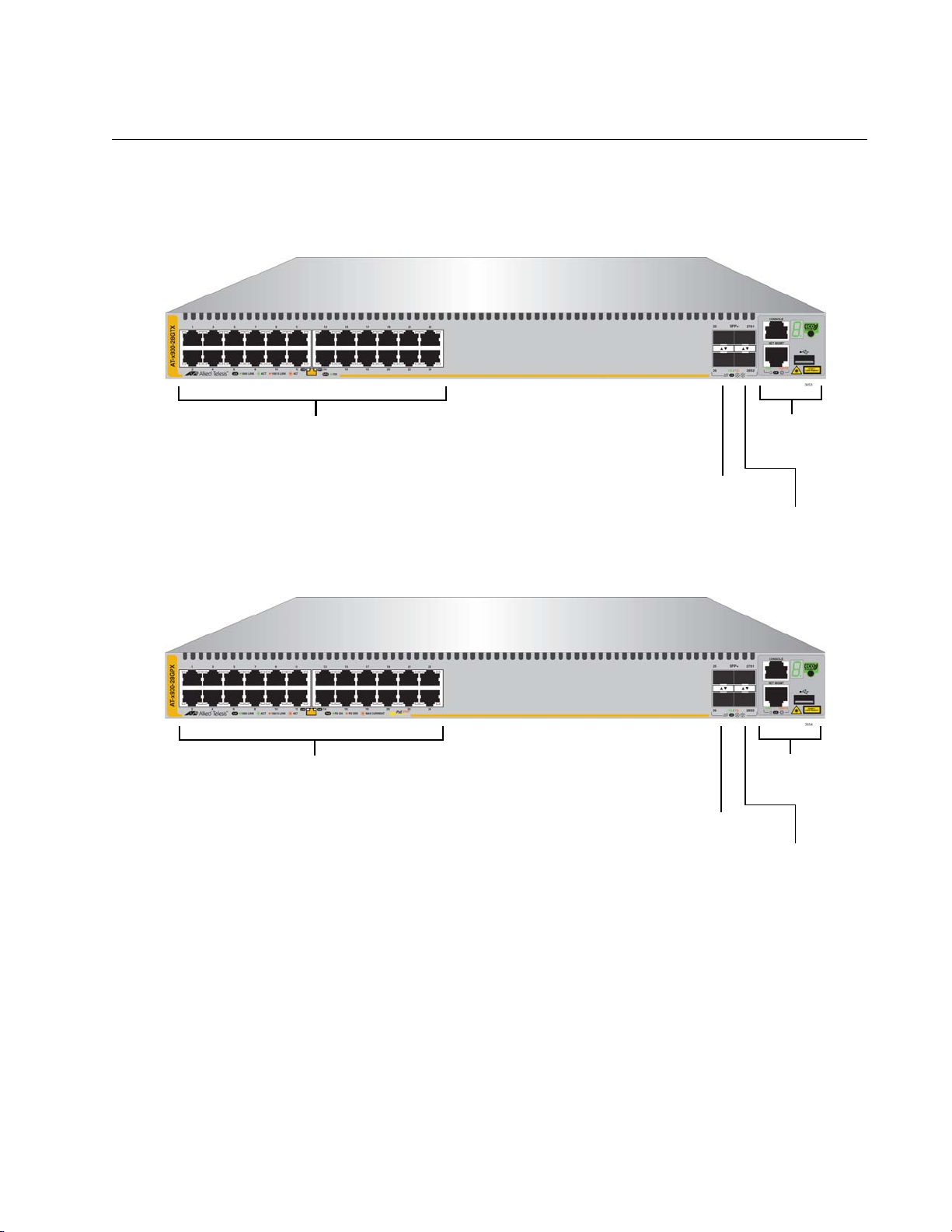
The front panels of the x930 Series switches are shown in Figure 1 and
Figure 2 on page 22.
Figure 1. Front Panels of the AT-x930-28GTX and AT-x930-28GPX
Switches
AT-x930-28GPX
AT-x930-28GTX
10/100/1000Base-T Ports
SFP+ Slots
Management
Panel
SFP+ or
Stacking Slots
SFP+ Slots
Management
Panel
SFP+ or
Stacking Slots
10/100/1000Base-T Ports
with PoE+
Chapter 1: Overview
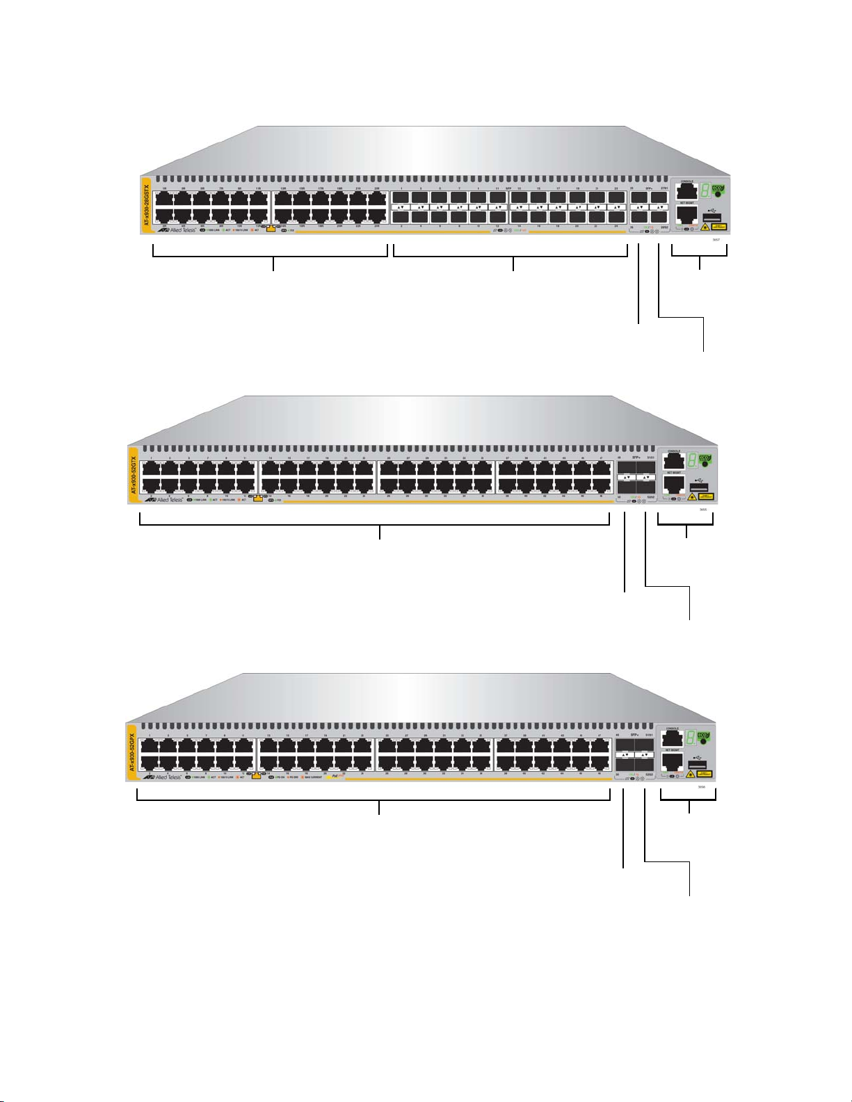
22
Figure 2. Front Panels of the AT-x930-28GSTX, AT-x930-52GTX, and AT-
x930-52GPX Switches
AT-x930-52GPX
AT-x930-52GTX
SFP+ Slots
Management
Panel
SFP+ or
Stacking Slots
10/100/1000Base-T Ports
SFP+ Slots
Management
Panel
SFP+ or
Stacking Slots
10/100/1000Base-T Ports
with PoE+
AT-x930-28GSTX
SFP+ Slots
Management
Panel
SFP+ or
Stacking Slots
10/100/1000Base-T Ports
SFP Slots
x930 Series Installation Guide for Stand-alone Switches
23
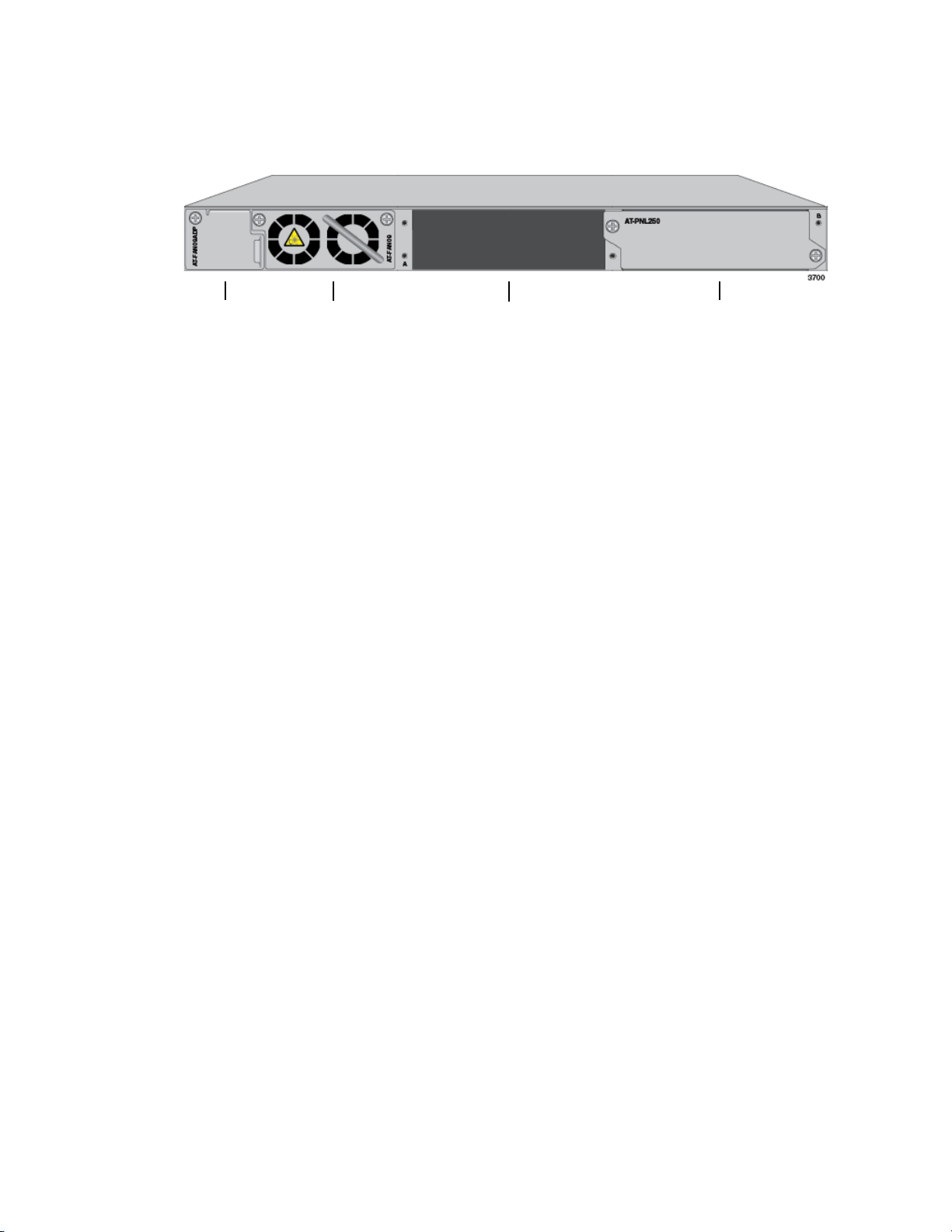
Figure 3 shows the back panel. The back panel is the same on all of the
switches.
Figure 3. Back Panel
AT-FAN09
Fan Module
Power Supply Slot B
Power Supply Slot A
AT-FAN09ADP
Module
with AT-PNL250 Blank Panel
Chapter 1: Overview
24
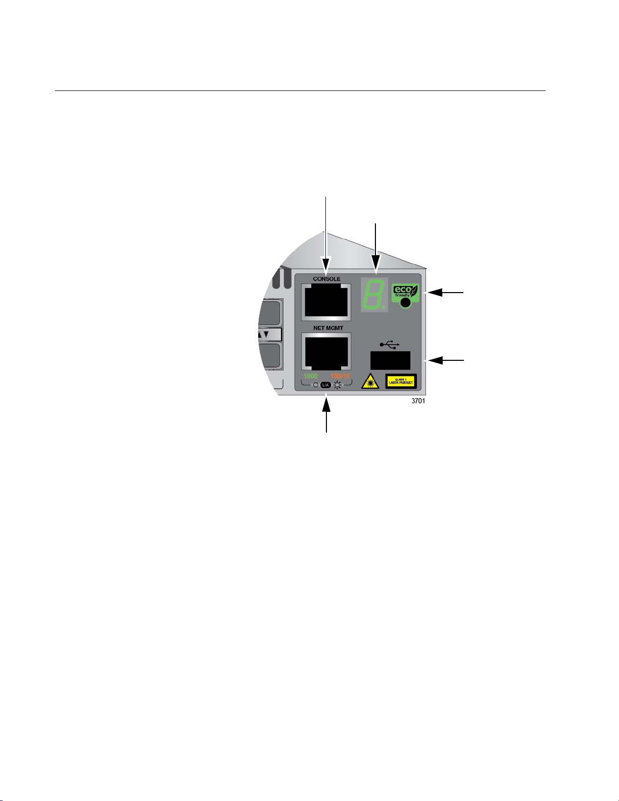
Management Panel
Figure 4 identifies the components in the management panel on the x930
Series switches.
Figure 4. Management Panel
Console
eco-friendly
Button
Switch
Port
ID LED
Management
USB Port
Network Management Port
x930 Series Installation Guide for Stand-alone Switches
25
Power Supplies
There are five power supply models for the x930 Series switches. The
models are listed here:
AT-PWR150
AT-PWR250
AT-PWR250-80
AT-PWR800
AT-PWR1200
The top three models are primarily intended for the non-PoE AT-x930-
28GTX, AT-x930-28GSTX, and AT-x930-52GTX Switches. The bottom
two power supplies are for the PoE AT-x930-28GPX and AT-x930-52GPX
Switches.
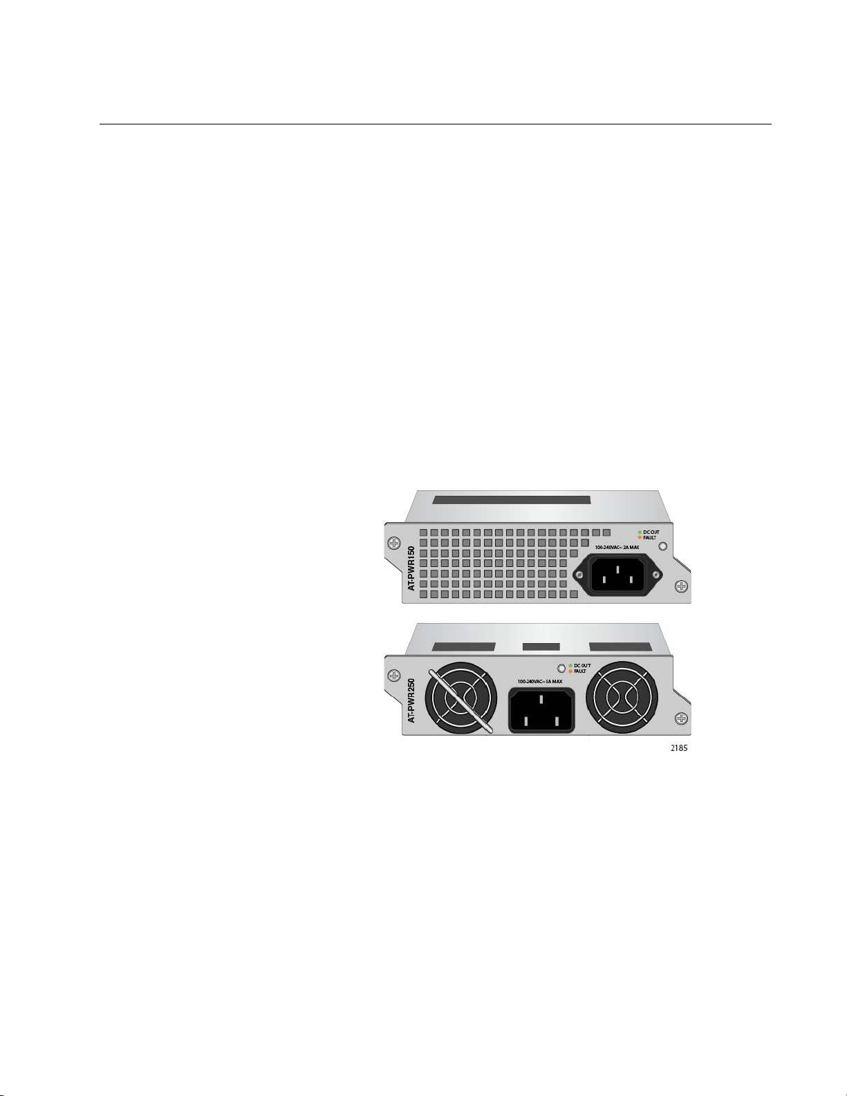
Figure 5 illustrates the AT-PWR150 and AT-PWR250 Power Supplies.
The two power supplies are functionally identical.
Figure 5. AT-PWR150 and AT-PWR250 Power Supplies
The two power supplies are primarily designed for the non-PoE switches
and have these operating characteristics:
The power supplies provide system power, but no PoE power.
A single power supply can power an entire non-PoE switch.
Installing two power supplies in a switch adds power redundancy.
The power supplies are not recommended for the PoE AT-x930-
28GPX and AT-x930-52GPX Switches because they do not have
power for PoE devices. You may install them into PoE switches,
but the switches will not be able to support PoE powered devices.
Chapter 1: Overview
26
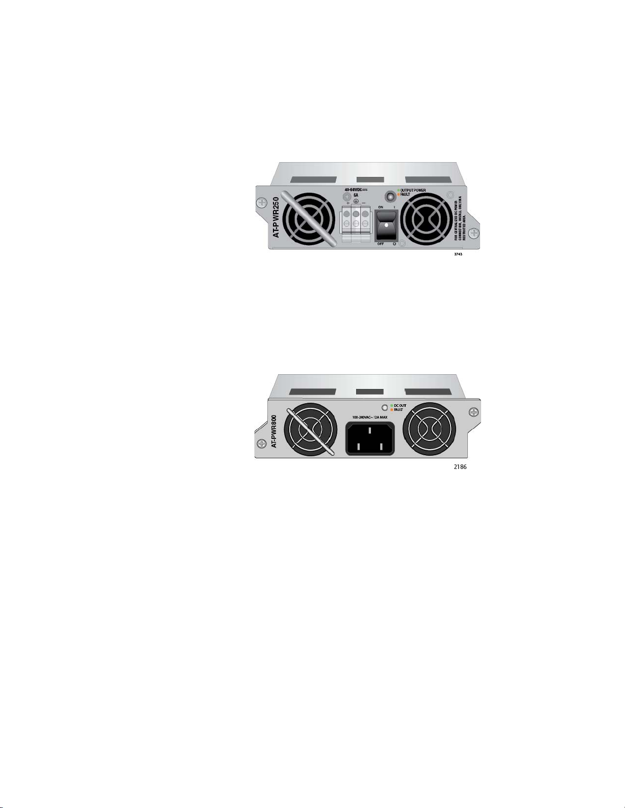
The AT-PWR250-80 DC Power Supply illustrated in Figure 6 has the
same operating characteristics as the AT-PWR150 and AT-PWR250
Power Supplies. It, too, is intended for the non-PoE switches because it
can supply system power, but no PoE power. The only difference is that
this power supply has a DC wiring connector instead of an AC connector,
for DC wiring environments.
Figure 6. AT-PWR250-80 Power Supply
Figure 7 illustrates the AT-PWR800 Power Supply.This power supply is
primarily intended for the PoE AT-x930-28GPX and AT-x930-52GPX
Switches. It provides both system power to the switch as well as up to 380
watts of PoE power for the powered devices connected to the network
ports.
Figure 7. AT-PWR800 Power Supply
A PoE switch with one AT-PWR800 Power Supply has the following power
characteristics:
Full system power
380 watts of PoE power
A switch with two AT-PWR800 Power Supplies has these power
characteristics:
Full system power and redundant system power
Either 740 watts of PoE power or 380 watts of active PoE power
and 380 watts of redundant PoE power.
You may install the AT-PWR800 Power Supply in the non-PoE AT-x930-
28GTX and AT-x930-52GTX Switches. But because the switches do not
support PoE, the power supply will provide system power but no PoE
power.

x930 Series Installation Guide for Stand-alone Switches
27
The AT-PWR1200 Power Supply is shown in Figure 8. It is similar to the
AT-PWR800 Power Supply in that it is intended for the PoE AT-x930-
28GPX and AT-x930-52GPX Switches because it provides both system
power and power for PoE devices. The difference between them is the
amount of PoE power. The AT-PWR1200 Power Supply can provide up to
740 watts compared to 380 watts for the AT-PWR800 Power Supply.
Figure 8. AT-PWR1200 Power Supply
A PoE switch with one AT-PWR1200 Power Supply has the following
power characteristics:
Full system power
740 watts of power for PoE devices
A switch with two AT-PWR1200 Power Supplies has these power
characteristics:
Full system power and redundant system power
Either 1440 watts of PoE power or 740 watts of active PoE power
and 740 watts of redundant PoE power.
Guidelines Please review the following guidelines concerning power supplies:
The x930 Series Switches do not come with power supplies. The
power supplies must be ordered separately.
If you install two power supplies in the switch, they must both be
the same model. For example, you may install two AT-PWR800
Power Supplies or two AT-PWR1200 Power Supplies in a switch.
You may not install two different power supply models in the
switch.
The non-PoE AT-x930-28GTX AT-x930-28GSTX, and AT-x930-
52GTX Switches require only one power supply for full operations.
Installing a second power supply adds power redundancy, which
protects against interruptions to network operations in the event
one power supply loses power or fails. Power redundancy is
available only when both AC or DC connectors on the switch are
connected to power sources.

Chapter 1: Overview
28
The PoE AT-x930-28GPX and AT-x930-52GPX Switches also
require only one power supply for network operations, excluding
PoE. The switches can continue to operate even if one power
supply fails or loses power.
The second power supply in the PoE switches either increases the
amount of power for PoE or adds PoE redundancy. For further
information, refer to “Power Budget” on page 33.
The DC wires for the AT-PWR250-80 DC Power Supply should be
routed from a DC load center containing appropriate overcurrent
branch protection for each DC feed, as required by the cognizant
local electrical authority.
Refer to “Technical Specifications” on page 149 for the input voltage
ranges.
Warning
Power cord is used as a disconnection device. To de-energize
equipment, disconnect the power cord. E3
Warning
This unit might have more than one power cord. To reduce the risk
of electric shock, disconnect all power cords before servicing the
unit. E30
Note
The AT-PWR150, AT-PWR250, AT-PWR800, and AT-PWR1200
Power Supplies are powered on or off by connecting or
disconnecting the power cords. The AT-PWR250-80 Power Supply
is powered on or off with its On/Off power switch or by deactivating
the DC circuit.

x930 Series Installation Guide for Stand-alone Switches
29
10/100/1000Base-T Twisted Pair Ports
The twisted pair ports on the switches are described in this section.
Speed The ports can operate at 10, 100, or 1000 Mbps. The speeds may be set
manually using the management software or automatically with Auto-
Negotiation (IEEE 802.3u), the default setting.
Note
The ports must be set to Auto-Negotiation to function at 1000 Mbps
and are not compatible with devices that are not IEEE 802.3u
compliant.
Duplex Mode The twisted pair ports can operate in either half- or full-duplex mode. The
duplex mode of a port, like port speed, may be set manually using the
management software or automatically with Auto-Negotiation (IEEE
802.3u), the default setting.
The speed and duplex mode settings of a port may be set independently
of each other. For example, a port may be configured such that its speed
is set manually while its duplex mode is established through Auto-
Negotiation.
Note
A switch port should not use Auto-Negotiation to set its duplex mode
if it is connected to a network device that does not support Auto-
Negotiation for 10 or 100 Mbps operation and has a fixed duplex
mode of full-duplex. Otherwise, a duplex-mode mismatch may occur
in which a switch port and a network device operate at different
duplex modes. The duplex modes of switch ports that are connected
to network devices that do not support Auto-Negotiation should be
set manually through the management software.
Wiring
Configuration
The wiring configuration of a port operating at 10 or 100 Mbps can be MDI
or MDI-X. The wiring configurations of a switch port and a network device
connected with straight-through twisted pair cabling have to be opposite,
such that one device is using MDI and the other MDI-X. For instance, a
switch port has to be set to MDI-X if it is connected to a network device set
to MDI.
You may set the wiring configurations of the ports manually or let the
switch configure them automatically with auto-MDI/MDI-X (IEEE 802.3ab-
compliant). This feature enables the switch to automatically negotiate with
network devices to establish their proper settings.

Chapter 1: Overview
30
The MDI and MDI-X settings do not apply when ports are operating at
1000 Mbps.
Maximum
Distance
The ports have a maximum operating distance of 100 meters (328 feet).
Cable
Requirements
The cable requirements of the ports are given in Table 2.
Note
For the cable requirements for the ports on the AT-x930-28GPX and
AT-x930-52GPX Switches for PoE devices, refer to Table 4 on
page 32.
Port Pinouts Refer to Table 29 on page 156 and Table 30 on page 156 for the port
pinouts of the 10/100/1000Base-T twisted pair ports.
Table 2. Twisted Pair Cable for the 10/100/1000Base-T Ports
Cable Type 10Mbps 100Mbps 1000Mbps
Standard TIA/EIA 568-B-
compliant Category 3 shielded
or unshielded cabling with 100
ohm impedance and a
frequency of 16 MHz.
Yes Yes No
Standard TIA/EIA 568-A-
compliant Category 5 or TIA/
EIA 568-B-compliant Enhanced
Category 5 (Cat 5e) shielded or
unshielded cabling with 100
ohm impedance and a
frequency of 100 MHz.
Yes Yes Yes
Standard TIA/EIA 568-B-
compliant Category 6 or 6a
shielded cabling.
Yes Yes Yes
Loading...