


 Loading...
ALLIED Telesis AT-AR020 PRI E1, AT-AR021 S BRI- S, AT-AR021 U BRI-U, AT-AR022 ETH, AT-AR023 SYN Service Manual
...Port Interface Card |
Hardware Reference |
AT-AR020 PRI E1/T1 |
AT-AR021 (S) BRI- S/T |
AT-AR021 (U) BRI-U |
AT-AR022 ETH |
AT-AR023 SYN |
AT-AR024 ASYN4 |
AT-AR026 4ETH |
AT-AR027 VoIP-FXS |
Port Interface Card Hardware Reference
Document Number C613-03023-00 REV M.
© 1999-2007 Allied Telesis Inc. All rights reserved. No part of this publication may be reproduced without prior written permission from Allied Telesis Inc.
Allied Telesis Inc. reserves the right to change specifications and other information in this document without prior written notice. The information provided herein is subject to change without notice. In no event shall Allied Telesis Inc. be liable for any incidental, special, indirect, or consequential damages whatsoever, including but not limited to lost profits, arising out of or related to this manual or the information contained herein, even if Allied Telesis Inc. has been advised of, known, or should have known, the possibility of such damages.
All company names, logos, and product designs that are trademarks or registered trademarks are the property of their respective owners.

Contents |
|
Devices Covered By This Document ................................................................... |
4 |
Hardware Overview .......................................................................................... |
4 |
Common Traits ........................................................................................... |
4 |
AT-AR020 PRI E1/T1 PIC .................................................................................... |
5 |
AT-AR021(S) BRI-S/T PIC .................................................................................... |
7 |
AT-AR021(U) BRI-U PIC ..................................................................................... |
9 |
AT-AR022 ETH PIC .......................................................................................... |
10 |
AT-AR023 SYN PIC .......................................................................................... |
11 |
AT-AR024 ASYN4 PIC ..................................................................................... |
12 |
AT-AR026 4ETH PIC ........................................................................................ |
13 |
AT-AR027 VoIP-FXS PIC ................................................................................... |
17 |
PIC Interfaces .................................................................................................. |
19 |
Asynchronous Interface ............................................................................ |
19 |
Synchronous Interface .............................................................................. |
20 |
Ethernet Interfaces ................................................................................... |
20 |
Basic Rate ISDN Interfaces ........................................................................ |
21 |
Primary Rate ISDN Interface ...................................................................... |
22 |
VoIP FXS Interface .................................................................................... |
22 |
Cables and Loopback Plugs for PICs ................................................................ |
23 |
Transition Cables for the AT-AR023 PIC ..................................................... |
23 |
ISDN Interface Cables ............................................................................... |
31 |
BT Adaptor Cable for the AT-AR027 PIC ................................................... |
32 |
Terminal and Modem Cables .................................................................... |
32 |
Ethernet Transceivers and AUI Cables ....................................................... |
34 |
Loopback Plugs for Testing Interfaces ....................................................... |
35 |
Hot Swapping the AR040 NSM with PICs Installed .......................................... |
38 |
Behaviour of Hot Swapped Interfaces ....................................................... |
38 |
PIC Testing and Verification ............................................................................. |
40 |
Test Facility ..................................................................................................... |
43 |
Asynchronous Interface Tests .................................................................... |
44 |
WAN Port Tests ......................................................................................... |
44 |
Troubleshooting .............................................................................................. |
45 |
For More Information ...................................................................................... |
45 |
Contacting Us .......................................................................................... |
45 |

4 |
Port Interface Card |
Devices Covered By This Document
This Hardware Reference includes information on the following devices:
■AT-AR020 PRI E1/T1
■AT-AR021 (S) BRI- S/T
■AT-AR021 (U) BRI-U
■AT-AR022 ETH
■AT-AR023 SYN
■AT-AR024 ASYN4
■AT-AR026 4ETH
■AT-AR027 VoIP-FXS
The latest Hardware Reference can be found at
www.alliedtelesis.co.uk/site/products/ .
Hardware Overview
PICs provide a cost effective and flexible mechanism for adding new or additional network interfaces to switches or routers. By adding or changing PICs, network interface capabilities can be upgraded without replacing the switch or router. A PIC can provide additional network interfaces, or can be replaced with a different PIC to provide alternative interface types.
The following PICs are currently available:
■“AT-AR020 PRI E1/T1 PIC” with primary rate ISDN
■“AT-AR021(S) BRI-S/T PIC” with basic rate ISDN
■“AT-AR021(U) BRI-U PIC” with basic rate ISDN
■“AT-AR022 ETH PIC” with a dual Ethernet 10BASE-T/AUI port
■“AT-AR023 SYN PIC” with a single 2Mbps synchronous port
■“AT-AR024 ASYN4 PIC” with four asynchronous ports
■“AT-AR026 4ETH PIC” with four 10BASE-T/100BASE-TX ports
■“AT-AR027 VoIP-FXS PIC” with two Foreign Exchange Voice over IP ports
See the following hardware descriptions for more information on each PIC.
Common Traits
This section outlines the hardware features that are common to all PIC models.
Environmental Conditions
•Operating temperature range: 0 ºC to 40 ºC (32 ºF to 104 ºF)
•Storage temperature range: -25 ºC to 70 ºC (-13 ºF to 158 ºF)
•Relative humidity range: 5% to 95% non-condensing
C613-03023-00 REV M

Hardware Reference |
5 |
Regulatory Standards
•Emissions: EN55022 class A, FCC class A, and VCCI class A, AS/NZS CISPR22
•Immunity: EN55024
•Safety: UL60950-1, CAN/CSA-C22.2 No. 60950-1-03, EN60950-1, AS/NZS60950.1
AT-AR020 PRI E1/T1 PIC
The AT-AR020 PRI E1/T1 PIC provides a single G.703/Primary Rate ISDN
WAN port with an RJ-45 connector.
The card supports both E1 and T1 operation. A jumper selects the required option and impedance. A second jumper selects NT (Network Terminator) or TE (Terminal Equipment) mode, and the current mode is displayed by the NT LED. The normal operating mode is LT. Jumper locations are shown in Figure 2 on page 6, and jumper functions are listed in Table 2 on page 6.
The AT-AR020 PRI E1/T1 PIC is shown in Figure 1, and the functions of the
LEDs are listed in Table 1.
Figure 1: AT-AR020 PRI E1/T1 PIC
PRI E1/T1 (RJ45 connector)
D Data
B Data
PRI E1/T1
Active
NT
LEDs |
LEDs |
|
PIE1T1R |
Table 1: AT-AR020 PRI E1/T1 PIC LED functions
LED |
Function |
|
|
D Data |
[ISDN mode only] Lit when HDLC packets are being exchanged between |
|
the switch or router and the ISDN switch over the D (signalling) channel. |
|
|
B Data |
Lit when HDLC packets are being exchanged between the switch or |
|
router and another end system device (normally another switch or router) |
|
over any of the B (data) channels. |
|
|
Active |
Lit whenever operational (i.e., no RAI or AIS) frames are being received. |
|
|
NT |
[ISDN mode only] Lit when the PRI1 is operating in NT mode. This LED |
|
should not be lit during normal operation. |
|
|
C613-03023-00 REV M

6 |
Port Interface Card |
Figure 2: Location of jumpers on the AT-AR020 PRI E1/T1 PIC board
LED
Active
NT
 J2 (E1/T1)
 J1 (NT/TE)
RJ45
PRI
LED
D Data
B Data
S/N
PIC CONNECTOR
PIE1T1C
Table 2: Functions of jumpers on the AT-AR020 PRI E1/T1 PIC board
Jumper |
Function |
Default |
|
|
|
J1 |
Selects ISDN NT mode (installed) or TE mode (not installed). |
Not installed. |
|
|
|
J2 |
Selects T1 mode (installed) or E1 mode (not installed). |
Installed. |
|
|
|
Jumper J1 is factory set to ISDN TE mode for normal operation and should not be changed without contacting your ISDN service provider, or authorised Allied Telesis distributor or reseller.
Earlier versions of this card also have a J3 interface jumper. If present, this jumper must be installed for E1 mode and removed for T1 mode.
Caution Remove the data cable from the RJ-45 connector before attempting to remove the PIC from the switch or the router.
C613-03023-00 REV M

Hardware Reference |
7 |
AT-AR021(S) BRI-S/T PIC
The AT-AR021(S) BRI-S/T PIC provides a single Basic Rate ISDN S/T WAN port. The BRI port has an RJ-45 connector.
The AT-AR021(S) PIC is shown in Figure 3 and the functions of the LEDs are listed in Table 3. Jumper locations are shown in Figure 4 on page 8, and jumper functions are listed in Table 4 on page 8.
Figure 3: AT-AR021(S) BRI-S/T PIC
ISDN BRI S/T port (RJ45 connector)
B1
B2
BRI S/T
Active
D
LEDs |
LEDs |
PIBRI1R
Table 3: AT-AR021(S) BRI-S/T PIC LED functions
LED |
Function |
|
|
B1, B2 |
For on-demand ISDN, lit when there is a call up over the respective B |
|
channel and flashing when data is being exchanged. |
|
For permanent circuits, lit when HDLC packets are being exchanged |
|
between the switch or router and another TE end system device (normally |
|
another switch or router) over the respective B (data) channel. |
|
|
Active |
Lit when the BRI has successfully completed the exchange of INFO 1 and |
|
INFO 2 signals, and INFO 3 and INFO 4 signals are present on the link. This |
|
means that the ISDN interface is correctly connected to a working NT |
|
device. |
|
|
D |
Lit when HDLC packets are being exchanged between the switch or |
|
router and the ISDN switch over the D (signalling) channel. |
|
|
C613-03023-00 REV M
8 |
Port Interface Card |
Figure 4: Location of jumpers on the AT-AR021(S) BRI-S/T PIC board
LED
Active
D
RJ45
BRI
LED
B1
B2
|
|
J1 |
|
|
J2 |
ISDN TX |
ISDN RX |
||||
TERMINATION |
TERMINATION |
||||
PIC CONNECTOR
PIBRI1C
Table 4: Functions of jumpers on the AT-AR021(S) BRI-S/T PIC board
Jumper |
Function |
|
|
J1 |
100Ω termination for TX. |
|
|
J2 |
100Ω termination for RX. |
|
|
In North America, the ST interface must be supplied from a UL listed network terminating device such as NT1, and the cable length between the AR021(S) PIC and the NT1 device must be less than 1000 metres.
The termination jumpers (J1 and J2) are normally removed as the building wiring will provide the correct termination for an ISDN TE-to-NT circuit. When the BRI is connected in a point-to-point configuration, J1 and J2 may need to be installed to terminate the line pairs with internal 100Ω resistors. For detailed information, see the Integrated Services Digital Network (ISDN) chapter of the Software Reference or Reference Manual for your switch or router.
If you are unsure of whether to terminate the line or not, contact your ISDN service provider, or your authorised Allied Telesis distributor or reseller.
C613-03023-00 REV M

Hardware Reference |
9 |
AT-AR021(U) BRI-U PIC
The AT-AR021(U) BRI-U PIC provides a single Basic Rate ISDN U Interface
WAN port. The BRI port has an RJ-45 connector.
There are no user-configurable jumpers or dip switches on the AT-AR021(U)
BRI-U PIC board.
The AT-AR021(U) PIC is shown in Figure 5, and the functions of the LEDs are listed in Table 5.
Figure 5: AT-AR021(U) BRI-U PIC
ISDN BRI U interface (RJ45 connector)
BRI U
B1 Active
B2 D
|
|
LEDs |
|
|
|
PIBRI1UR |
|
|
|
|
|
Table 5: AT-AR021(U) BRI-U PIC LED functions |
|||
|
|
|
|
LED |
Function |
||
|
|
|
|
B1, B2 |
Lit when HDLC packets are being exchanged between the switch or |
||
|
|
router and another TE end system device (normally another switch or |
|
|
|
router) over the respective B (data) channel. |
|
|
|
For ISDN, lit when there is a call up over the respective B channel and |
|
|
|
flashing when data is being exchanged. |
|
|
|
|
|
Active |
Lit when the U interface is in the Activated state (i.e., it is fully operational |
||
|
|
at layer 1). |
|
|
|
|
|
D |
Lit when HDLC packets are being exchanged between the switch or |
||
|
|
router and the ISDN switch over the D (signalling) channel. |
|
|
|
|
|
Caution Before removing this PIC, ensure that the power to the switch or router has been disconnected and that the ISDN connection has been removed from the BRI U interface connector. Dangerous voltages may be present on an ISDN line interface.
C613-03023-00 REV M
10 |
Port Interface Card |
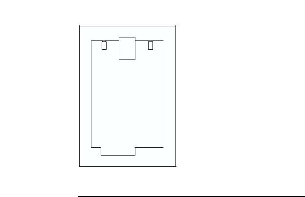
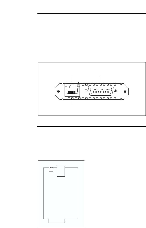
AT-AR022 ETH PIC
The AT-AR022 ETH PIC provides a dual Ethernet 10BASE-T/AUI port. Only one interface type can be active at any one time and the PIC automatically senses which interface is in use. The 10BASE-T interface uses an RJ-45 connector and the AUI interface uses a DB15 connector.
AT-AR022 ETH PICs are not recommended for use in AT-AR040 NSM PIC bays because performance of these interfaces is likely to be reduced and packet loss may occur.
The AT-AR022 ETH PIC is shown in Figure 6, and the functions of the LEDs are listed in Table 6.
Figure 6: AT-AR022 ETH PIC
|
Ethernet AUI port |
LEDs |
(DB15 connector) |
Data |
Link |
ETH |
|
Ethernet 10BASET port (RJ45 connector)
PIETH1R
Table 6: AT-AR022 ETH PIC LED functions
LED |
Function |
|
|
Link |
Lit when the Ethernet interface is connected to a device (e.g. a hub) which is |
|
generating link pulses. |
|
|
Data |
Lit when data is being transmitted or received over the Ethernet interface. |
|
|
The AT-AR022 PIC is a single card. Figure 7 shows the layout of the board.
Figure 7: Location of main components on the AT-AR022 ETH PIC
Data
LED LED
Link
RJ45
ETHERNET 10BASET
PIC CONNECTOR
PIETH1C
C613-03023-00 REV M
Hardware Reference |
11 |
AT-AR023 SYN PIC
The AT-AR023 SYN PIC provides a single synchronous port operating at speeds up to 2Mbps. The synchronous port has a 50-way AMPLIMITE universal connector which supports RS-232/V.28, V.35 and X.21 interface standards in DTE and DCE modes.
A transition cable is required to convert the AMPLIMITE connector to the correct physical interface. The switch does not need to be rebooted to change the interface type.
There are no user-configurable jumpers or dip switches on the AT-AR023 SYN
PIC board.
The AT-AR023 SYN PIC is shown in Figure 8, and the functions of the LEDs are listed in Table 7.
Figure 8: AT-AR023 SYN PIC
Synchronous port (AMPLIMITE 50-way connector)
SYN
Tx
Rx
LEDs
PISYN1R
Table 7: AT-AR023 SYN PIC LED functions
LED |
Function |
|
|
Tx |
Lit when data is being transmitted over the synchronous interface. |
|
|
Rx |
Lit when data is being received on the synchronous interface. |
|
|
C613-03023-00 REV M

12 |
Port Interface Card |
AT-AR024 ASYN4 PIC
The AT-AR024 ASYN4 PIC provides four additional asynchronous RS-232 ports with RJ-45 connectors for use up to 115 Kbps.
There are no user-configurable jumpers or dip switches on the AT-AR024
ASYN4 PIC board.
The AT-AR024 ASYN4 PIC is shown in Figure 9. The ASYN4 PIC does not have LEDs.
Figure 9: AT-AR024 ASYN4 PIC
|
Asynchronous ports (RJ45 connector) |
3 |
0 |
ASYN |
|
PIASYN4R
C613-03023-00 REV M

Hardware Reference |
13 |
AT-AR026 4ETH PIC
The AT-AR026 4ETH PIC provides four 10BASE-T/100 BASE-TX autonegotiating ports. The ports support wire speed unmanaged layer 2 switching and have RJ-45 connectors.
The AT-AR026 4ETH PIC is shown in Figure 10, and the functions of the LEDs are listed in Table 8 on page 14.
AT-AR026 4ETH PICs are not recommended for use in AT-AR040 NSM PIC bays because performance of these interfaces is likely to be reduced and packet loss may occur.
Figure 10: AT-AR026 4ETH PIC
|
10BaseT/100BaseTX Ethernet ports |
|
(RJ45 connectors) |
4 |
1 |
10/100 ETH |
|
LEDs
AR026PIC
AT-AR026 features include:
•Five integrated switch ports with physical layer transceivers (four 10/ 100 Ethernet switch ports, and one fixed 10 Mbps port acting as the PIC to base unit connector)
•128 kbytes of frame buffering SRAM
•1.4 Gbps high performance memory bandwidth
•10BASE-T and 100BASE-TX modes of operation
•LED indicators for link, activity, full/half duplex, and port speed
•Hardware based 10/100, full/half duplex, flow control, and autonegotiation
•Individual port forced modes (full duplex, 100BASE-TX) when autonegotiation is disabled
•Wire speed reception and transmission
•Integrated address look-up engine, supporting 1K absolute MAC addresses
•Automatic address learning, address aging, and address migration
•Broadcast storm protection
•Full duplex IEEE 802.3x flow control
•Half duplex back pressure flow control
•MDI/MDI-X auto cross over support
C613-03023-00 REV M

14 |
Port Interface Card |
Some features (such as autonegotiation, buffer size, and MAC address aging) are configured by adding or removing links on the PIC’s PCB. Table 9 on page 15 lists the configurable features, their respective links, and their default settings.
Table 8: AT-AR026 4ETH PIC LED functions (Two LEDs per port)
LED |
Function |
|
|
Left |
Lit when the port is operating at 100Mbps and full duplex. |
|
|
Right |
Lit when a link has been established. Flashing when data is being transmitted |
|
through the port. |
|
|
The AT-AR026 PIC is a single card. Figure 11 shows the layout of its board and configurable links. AT-AR026 PICs do not support the AlliedWare Diagnostic or Test Facility modules.
AT-AR026 PICs include a switch chip that switches independently of the switch, router, or NSM that the PIC is installed in. The show interface command will show each correctly installed AT-AR026 as a single interface (the PIC connector). The 10/100 ‘front side’ Ethernet ports will not be shown.
Figure 11: Location of user configurable links on the AR026 4ETH PIC
Link Detail |
Configurable links |
Link
1 2 3 Pads
Link Options
Up = 10kΩ link between pads 1 and 2
Down = 1kΩ link between pads 2 and 3
Floating = No links
All configurable links use 603 resistors
Links 22, 31, 40, and MRXD 3 are fixed and cannot be configured
PIC connector
Ethernet ports
AR026Card
C613-03023-00 REV M
Loading...