


 Loading...
AT-8000 Series
Layer 2 Fast
Ethernet
Switches
AT-8012M AT-8012M-QS
AT-8016F/xx (MT, SC, and ST) AT-8024
AT-8024GB
AT-8024M
AT-8026FC
AT-8026T
AT-8088/xx (MT and SC)
Installation
Guide
PN 613-50244-00 Rev H
Copyright © 2004 Allied Telesyn, Inc.
www.alliedtelesyn.com
All rights reserved. No part of this publication may be reproduced without prior written permission from Allied Telesyn, Inc.
All other product names, company names, logos or other designations mentioned herein are trademarks or registered trademarks of their respective owners.
Allied Telesyn, Inc. reserves the right to make changes in specifications and other information contained in this document without prior written notice. The information provided herein is subject to change without notice. In no event shall Allied Telesyn, Inc. be liable for any incidental, special, indirect, or consequential damages whatsoever, including but not limited to lost profits, arising out of or related to this manual or the information contained herein, even if Allied Telesyn, Inc. has been advised of, known, or should have known, the possibility of such damages.
Electrical Safety and Emission
Statement
Standards: This product meets the following standards.
U.S. Federal Communications Commission
RADIATED ENERGY
Note: This equipment has been tested and found to comply with the limits for a Class A digital device pursuant to Part 15 of the FCC Rules. These limits are designed to provide reasonable protection against harmful interference when the equipment is operated in a commercial environment. This equipment generates, uses, and can radiate radio frequency energy and, if not installed and used in accordance with this instruction manual, may cause harmful interference to radio communications. Operation of this equipment in a residential area is likely to cause harmful interference in which case the user will be required to correct the interference at his own expense.
Note: Modifications or changes not expressly approved by the manufacturer or the FCC can void your right to operate this equipment.
Canadian Department of Communications
This Class A digital apparatus meets all requirements of the Canadian Interference-Causing Equipment Regulations.
Cet appareil numérique de la classe A respecte toutes les exigences du Règlement sur le matériel brouilleur du Canada.
RFI Emission |
FCC Class B, EN55022 Class B, VCCI Class B, C-TICK, EN61000-3-2, |
|
EN61000-3-3 1 |
Warning: In a domestic environment this product may cause radio interference in which case the user may be required to take adequate measures. 2
Immunity |
EN55024 3 |
Electrical Safety |
UL60950 (cULus), EN60950 (TUV) 4 |
Laser |
EN60825 5 |
Important: Appendix C contains translated safety statements for installing this equipment. When you see the , go to Appendix C for the translated safety statement in your language.
Wichtig: Anhang C enthält übersetzte Sicherheitshinweise für die Installation dieses Geräts. Wenn Sie sehen, schlagen Sie in Anhang C den übersetzten Sicherheitshinweis in Ihrer Sprache nach.
Vigtigt: Tillæg C indeholder oversatte sikkerhedsadvarsler, der vedrører installation af dette udstyr. Når De ser symbolet , skal De slå op i tillæg C og finde de oversatte sikkerhedsadvarsler i Deres eget sprog.
Belangrijk: Appendix C bevat vertaalde veiligheidsopmerkingen voor het installeren van deze apparatuur. Wanneer u de ziet, raadpleeg Appendix C voor vertaalde veiligheidsinstructies in uw taal.
Important : L'annexe C contient les instructions de sécurité relatives à l'installation de cet équipement. Lorsque vous voyez le symbole , reportez-vous à l'annexe C pour consulter la traduction de ces instructions dans votre langue.
Tärkeää: Liite C sisältää tämän laitteen asentamiseen liittyvät käännetyt turvaohjeet. Kun näet -symbolin, katso käännettyä turvaohjetta liitteestä C.
Importante: l’Appendice C contiene avvisi di sicurezza tradotti per l’installazione di questa apparecchiatura. Il simbolo , indica di consultare l’Appendice C per l’avviso di sicurezza nella propria lingua.
Viktig: Tillegg C inneholder oversatt sikkerhetsinformasjon for installering av dette utstyret. Når du ser , åpner du til Tillegg C for å finne den oversatte sikkerhetsinformasjonen på ønsket språk.
Importante: O Anexo C contém advertências de segurança traduzidas para instalar este equipamento. Quando vir o símbolo , leia a advertência de segurança traduzida no seu idioma no Anexo C.
Importante: El Apéndice C contiene mensajes de seguridad traducidos para la instalación de este equipo. Cuando vea el símbolo, vaya al Apéndice C para ver el mensaje de seguridad traducido a su idioma.
Obs! Bilaga C innehåller översatta säkerhetsmeddelanden avseende installationen av denna utrustning. När du ser , skall du gå till Bilaga C för att läsa det översatta säkerhetsmeddelandet på ditt språk.
3

Contents
Electrical Safety and Emission Statement |
............................................................................................................................................... 3 |
Contents ................................................................................................................................................................................................................... |
4 |
Preface ...................................................................................................................................................................................................................... |
7 |
How This Guide is Organized ............................................................................................................................................................................. |
7 |
Document Conventions ...................................................................................................................................................................................... |
8 |
Where to Find Web-based Guides ................................................................................................................................................................... |
9 |
Contacting Allied Telesyn ................................................................................................................................................................................. |
10 |
Online Support.............................................................................................................................................................................................. |
10 |
Email and Telephone Support ................................................................................................................................................................. |
10 |
Returning Products...................................................................................................................................................................................... |
10 |
For Sales or Corporate Information ....................................................................................................................................................... |
10 |
Management Software Updates............................................................................................................................................................. |
10 |
Chapter 1 |
|
Overview ................................................................................................................................................................................................................ |
11 |
Common Features ............................................................................................................................................................................................... |
12 |
Model Descriptions ............................................................................................................................................................................................. |
13 |
AT-8012M ........................................................................................................................................................................................................ |
13 |
AT-8012M-QS................................................................................................................................................................................................. |
14 |
AT-8016F/xx ................................................................................................................................................................................................... |
15 |
AT-8024............................................................................................................................................................................................................ |
16 |
AT-8024GB ...................................................................................................................................................................................................... |
17 |
AT-8024M ........................................................................................................................................................................................................ |
18 |
AT-8026FC....................................................................................................................................................................................................... |
19 |
AT-8026T.......................................................................................................................................................................................................... |
20 |
AT-8088/xx...................................................................................................................................................................................................... |
21 |
Hardware Features .............................................................................................................................................................................................. |
22 |
100Base-FX Fiber Optic Ports .......................................................................................................................................................................... |
23 |
Type of Connector........................................................................................................................................................................................ |
23 |
Speed ................................................................................................................................................................................................................ |
23 |
Duplex Mode.................................................................................................................................................................................................. |
23 |
Maximum Distance...................................................................................................................................................................................... |
23 |
Type of Cable ................................................................................................................................................................................................. |
23 |
10/100Base-TX Twisted Pair Ports .................................................................................................................................................................. |
24 |
Type of Connector........................................................................................................................................................................................ |
24 |
Speed ................................................................................................................................................................................................................ |
24 |
4
|
AT-8000 Series Fast Ethernet Switches Installation Guide |
Duplex Mode.................................................................................................................................................................................................. |
24 |
Maximum Distance...................................................................................................................................................................................... |
24 |
Type of Cabling ............................................................................................................................................................................................. |
25 |
Auto MDI/MDI-X ........................................................................................................................................................................................... |
25 |
Port Pinouts .................................................................................................................................................................................................... |
25 |
10/100/1000Base-T Twisted Pair Ports ......................................................................................................................................................... |
26 |
Type of Connector........................................................................................................................................................................................ |
26 |
Speed ................................................................................................................................................................................................................ |
26 |
Duplex Mode.................................................................................................................................................................................................. |
26 |
Maximum Distance...................................................................................................................................................................................... |
26 |
Type of Cable ................................................................................................................................................................................................. |
26 |
Auto MDI/MDI-X ........................................................................................................................................................................................... |
27 |
Port Pinouts .................................................................................................................................................................................................... |
27 |
Gigabit Interface Converter (GBIC) Expansion Slots ................................................................................................................................ |
28 |
Module Expansion Slots .................................................................................................................................................................................... |
29 |
Twisted Pair Port LEDs and the LED Mode Select Button ...................................................................................................................... |
30 |
Fiber Optic Port LEDs .......................................................................................................................................................................................... |
32 |
System LEDs ........................................................................................................................................................................................................... |
34 |
RS-232 Terminal Port .......................................................................................................................................................................................... |
35 |
Reset Button ........................................................................................................................................................................................................... |
36 |
RPS Connector ....................................................................................................................................................................................................... |
37 |
AC Power Connector ........................................................................................................................................................................................... |
38 |
DC Power Connector .......................................................................................................................................................................................... |
39 |
A Few Basics about Ethernet Switching ....................................................................................................................................................... |
40 |
MAC Address Table...................................................................................................................................................................................... |
40 |
Duplex Mode.................................................................................................................................................................................................. |
41 |
Store and Forward........................................................................................................................................................................................ |
42 |
Backpressure and Flow Control .............................................................................................................................................................. |
42 |
Network Topologies ............................................................................................................................................................................................ |
43 |
Power Workgroup Topology.................................................................................................................................................................... |
43 |
Collapsed Backbone - Hub Topology.................................................................................................................................................... |
44 |
Mixed Topology ............................................................................................................................................................................................ |
45 |
Collapsed Backbone - Switch Topology............................................................................................................................................... |
46 |
Chapter 2 |
|
Installation ............................................................................................................................................................................................................ |
47 |
Reviewing Safety Precautions ......................................................................................................................................................................... |
48 |
Selecting a Site for the Switch ......................................................................................................................................................................... |
49 |
Planning the Installation ................................................................................................................................................................................... |
50 |
Unpacking the Switch ........................................................................................................................................................................................ |
52 |
Installing the Switch in a Rack ......................................................................................................................................................................... |
53 |
Installing an Optional GBIC Module .............................................................................................................................................................. |
55 |
For the AT-8024GB....................................................................................................................................................................................... |
55 |
Installing an Optional Expansion or Stacking Module ........................................................................... |
................................................57 |
For the |
|
AT-8012M, |
|
AT-8012M-QS, AT-8016F/xx, AT-8024M, and AT-8088/xx ...................................................................................................................... |
57 |
Installing an Optional AT-RPS3004 Redundant Power Supply ............................................................................................................ |
60 |
For the AT-8016F/xx, AT-8088/xx, and AT-8024M............................................................................................................................ |
60 |
Cabling and Powering ON the Switch .......................................................................................................................................................... |
63 |
Wiring a DC Powered Unit ................................................................................................................................................................................ |
68 |
Starting a Local Management Session ......................................................................................................................................................... |
71 |
Warranty Registration ......................................................................................................................................................................................... |
74 |
Chapter 3 |
|
5
Contents |
|
Troubleshooting ................................................................................................................................................................................................ |
75 |
Appendix A |
|
Technical Specifications ................................................................................................................................................................................ |
79 |
Physical Specifications ....................................................................................................................................................................................... |
79 |
Environmental Specifications ......................................................................................................................................................................... |
80 |
Power Specifications .......................................................................................................................................................................................... |
81 |
Safety and Electromagnetic Emissions Certifications ............................................................................................................................ |
82 |
Standards ............................................................................................................................................................................................................... |
83 |
SNMP Support ...................................................................................................................................................................................................... |
84 |
RJ-45 Twisted Pair Port Pinouts ...................................................................................................................................................................... |
85 |
RS-232 Terminal Port Pinouts ......................................................................................................................................................................... |
87 |
RPS 16-pin Molex Connector Port Pinouts ................................................................................................................................................. |
88 |
MT-RJ Connector ................................................................................................................................................................................................. |
89 |
SC Type Connector ............................................................................................................................................................................................. |
90 |
ST Type Connector .............................................................................................................................................................................................. |
91 |
HSSDC Connector ................................................................................................................................................................................................ |
92 |
AT-8016F/xx, AT-8026FC, and AT-8088/xx Fiber Optic Port Specifications ................................................................................... |
93 |
Appendix B |
|
Translated Electrical Safety and Emission Information ................................................................................................................. |
94 |
6

Preface
This guide contains the hardware installation instructions for your new
AT-8000 Series Fast Ethernet Switch.
How This Guide is Organized
This manual contains the following chapters and appendices:
Chapter 1, Overview, describes the features and components of the switch.
Chapter 2, Installation, contains the installation instructions.
Chapter 3, Troubleshooting, provides information on how to resolve problems that might occur with the switch.
Appendix A, Technical Specifications, contains the switch’s technical specifications.
Appendix B, Translated Electrical Safety and Emission Information, contains translations of the warnings and cautions in the manual.
7
Preface
Document Conventions
This document uses the following conventions:
Note
Notes provide additional information.
Warning
Warnings inform you that performing or omitting a specific action may result in bodily injury.
 Caution
Cautions inform you that performing or omitting a specific action may result in equipment damage or loss of data.
8

AT-8000 Series Fast Ethernet Switches Installation Guide
Where to Find Web-based Guides
The installation and user guides for all Allied Telesyn products are available in Portable Document Format (PDF) from the Allied Telesyn web site at www.alliedtelesyn.com. You can view the documents online or download them onto a local workstation or server.
Once you have installed your AT-8000 Series Switch, refer to following manuals for instructions on how to manage and configure the unit. The manuals are available from the Allied Telesyn web site:
AT-S39 Management Software User’s Guide
PN 613-50245-00
AT-S39 Command Line Interface User’s Guide
PN 613-50354-00
9

Preface
Contacting Allied Telesyn
This section provides Allied Telesyn contact information for technical support as well as sales or corporate information.
Online Support You can request technical support online by accessing the Allied Telesyn Knowledge Base from the following web site: http://kb.alliedtelesyn.com. You can use the Knowledge Base to submit questions to our technical support staff and review answers to previously asked questions.
Email and
Telephone
Support
Returning
Products
For Sales or Corporate Information
Management
Software
Updates
For Technical Support via email or telephone, refer to the Support & Services section of the Allied Telesyn web site: http://www.alliedtelesyn.com.
Products for return or repair must first be assigned a Return Materials Authorization (RMA) number. A product sent to Allied Telesyn without a RMA number will be returned to the sender at the sender’s expense.
To obtain a RMA number, contact Allied Telesyn’s Technical Support at our web site: http://www.alliedtelesyn.com.
You can contact Allied Telesyn for sales or corporate information at our web site: http://www.alliedtelesyn.com. To find the contact information for your country, select Contact Us -> Worldwide Contacts.
New releases of management software for our managed products can be downloaded from one of the following web sites:
the Allied Telesyn web site: http://www.alliedtelesyn.com
the Allied Telesyn FTP server: http://ftp.alliedtelesyn.com.
To use the FTP server, enter ‘anonymous’ for the user name and your email address for the password.
10
Chapter 1
Overview
The AT-8000 Series Switches are managed, Layer 2 Fast Ethernet switches. They offer a wide range of features and capabilities, all designed to simplify the task of creating or expanding an Ethernet or Fast Ethernet network.
Table 1 lists the basic model configurations.
|
Table 1. Model Configurations |
|
|
Model |
Configuration |
|
|
|
|
AT-8012M |
Twelve 10/100Base-TX ports plus one expansion slot |
|
|
AT-8012M-QS |
Twelve 10/100Base-TX ports plus one expansion slot |
|
with NO fan |
|
|
AT-8016F/xx |
Sixteen 100Base-FX ports with MT-RJ, SC, or ST |
|
connectors plus two expansion slots |
|
|
AT-8024 |
Twenty-four 10/100Base-TX ports |
|
|
AT-8024GB |
Twenty-four 10/100Base-TX ports plus two GBIC |
|
slots |
|
|
AT-8024M |
Twenty-four 10/100Base-TX ports plus two |
|
expansion slots |
|
|
AT-8026FC |
Twenty-four 10/100Base-TX ports plus two |
|
100Base-FX ports with SC connectors |
|
|
AT-8026T |
Twenty-four 10/100Base-TX ports plus two 10/100/ |
|
1000Base-T Gigabit ports |
|
|
AT-8088/xx |
Eight 10/100Base-TX ports and eight 100Base-FX |
|
ports with SC or MT-RJ connectors plus two |
|
expansion slots |
|
|
11

Overview
Common Features
Features common to the AT-8000 Series Switches include:
Enhanced stacking
System and port LEDs
RS-232 port for out-of-band management
AT-S39 management software for local and remote management
Port trunking
Port mirroring
Port security
Multiple VLAN mode
802.1x Port Based Network Access Control
BootP and Dynamic Host Configuration Protocol (DHCP)
Internet Group Management Protocol (IGMP) snooping
Port-based and tagged VLANs (IEEE 802.1Q-compliant)
Auto-Negotiation (IEEE 802.3u-compliant)
Spanning Tree Protocol (IEEE 802.1D-compliant)
Quality of Service (IEEE 802.1p-compliant)
Backpressure and flow control (IEEE 802.3x-compliant)
Store and forward packet handling
Storage for up to 4K MAC addresses
Rapid Spanning Tree Protocol (IEEE 802.1W compliant)
SNMP v1
Management via RS-232 port, Telnet, and web browser
Broadcast storm control
Radius and TACACs + authentication
Bad cable detection
12

AT-8000 Series Fast Ethernet Switches Installation Guide
Model Descriptions
AT-8012M The AT-8012M is a 12-port 10/100Base-TX managed Fast Ethernet switch with one module expansion slot. The expansion slot is compatible with 100Base and 1000Base fiber optic and twisted pair port expansion modules and the AT-STACKM stacking module. The 10/100Base-TX twisted pair ports feature RJ-45 connectors with a maximum operating distance of 100 meters (328 feet). Refer to ”10/100Base-TX Twisted Pair Ports” on page 24 and ”Module Expansion Slots” on page 29 for additional information.
Figure 1 illustrates the front and back panels of the AT-8012M switch.
10/100Base-TX Ports |
LED Mode |
LED Mode |
||||||||
Select Button |
Select Button |
|||||||||
|
|
|||||||||
|
|
|
|
|
|
|
|
|
|
|
|
|
|
|
|
|
|
|
|
|
|
|
|
|
|
|
|
|
|
|
|
|
|
|
|
|
|
|
|
|
|
|
|
|
|
|
|
|
|
|
|
|
|
|
1 |
3 |
5 |
7 |
9 |
11 |
2 |
4 |
6 |
8 |
10 |
12 |
AT-8012M |
|
|
|
MODE |
RS-232 TERMINAL PORT STATUS |
||
10Base-T / 100Base-TX Fast Ethernet Switch |
COL |
|
|||||
|
|
|
|
|
|
|
|
1 |
3 |
5 |
7 |
9 |
11 |
100 |
|
LINK |
|
|
|
|
|
FULL |
FAULT |
MODE |
|
|
|
|
|
ACT |
MASTER |
|
|
|
|
|
|
||
LINK |
|
|
|
|
|
|
|
MODE |
|
|
|
|
|
|
PWR |
2 |
4 |
6 |
8 |
10 |
12 |
|
|
Module Expansion Slot |
Status LEDs |
RS-232 |
||||
Terminal Port |
||||||
|
|
|
|
|
||
|
|
|
|
|
|
|
|
|
|
|
|
|
|
|
|
|
|
|
|
|
|
|
|
|
|
|
|
AC Power
Connector
Figure 1. AT-8012M Front and Back Panels
13

Overview
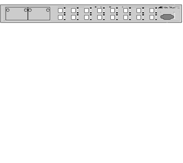
AT-8012M-QS The AT-8012M-QS is a 12-port 10/100Base-TX managed Fast Ethernet switch with one module expansion slot and operates without a fan. The expansion slot is compatible with 100Base and 1000Base fiber optic and twisted pair port expansion modules and the AT-STACKM stacking module. The 10/100Base-TX twisted pair ports feature RJ-45 connectors with a maximum operating distance of 100 meters (328 feet). Refer to ”10/100Base-TX Twisted Pair Ports” on page 24 and ”Module Expansion Slots” on page 29 for additional information.
Figure 1 illustrates the front and back panels of the AT-8012M-QS switch.
10/100Base-TX Ports |
LED Mode |
LED Mode |
||||||||
Select Button |
Select Button |
|||||||||
|
|
|||||||||
|
|
|
|
|
|
|
|
|
|
|
|
|
|
|
|
|
|
|
|
|
|
|
|
|
|
|
|
|
|
|
|
|
|
|
|
|
|
|
|
|
|
|
|
|
|
|
|
|
|
|
|
|
|
|
1 |
3 |
5 |
7 |
9 |
11 |
2 |
4 |
6 |
8 |
10 |
12 |
AT-8012M-QS |
|
|
MODE |
RS-232 TERMINAL PORT STATUS |
|||
10Base-T / 100Base-TX Fast Ethernet Switch |
COL |
|
|||||
|
|
|
|
|
|
|
|
1 |
3 |
5 |
7 |
9 |
11 |
100 |
|
LINK |
|
|
|
|
|
FULL |
FAULT |
MODE |
|
|
|
|
|
ACT |
MASTER |
|
|
|
|
|
|
||
LINK |
|
|
|
|
|
|
|
MODE |
|
|
|
|
|
|
PWR |
2 |
4 |
6 |
8 |
10 |
12 |
|
|
Module Expansion Slot |
|
|
|
|
|
|
|
|
|
|
|
|
|
|
|
|
|
|
|
|
|
|
|
|
|
|
|
|
|
|
|
|
|
|
|
|
|
Status LEDs |
|
|
|
|
|
|
|
|
|
|
|
|
|
|
|
RS-232 |
|||||||||||||||||||||||||||||||||||||||||||||||||||||||||||
|
|
|
|
|
|
|
|
|
|
|
|
|
|
|
|
|
|
|
|
|
|
|
|
|
|
|
|
|
|
|
|
|
|
|
|
|
|
|
|
|
|
|
|
|
|
Terminal Port |
|||||||||||||||||||||||||||||||||||||||||||||||||||||||||||||||||||
|
|
|
|
|
|
|
|
|
|
|
|
|
|
|
|
|
|
|
|
|
|
|
|
|
|
|
|
|
|
|
|
|
|
|
|
|
|
|
|
|
|
|
|
|
|
|
|
|
|
|
|
|
|
|
|
|
|
|
|
|
|
|
|
|
|
|
|
|
|
|
|
|
|
|
|
|
|
|
|
|
|
||||||||||||||||||||||||||||||||
|
|
|
|
|
|
|
|
|
|
|
|
|
|
|
|
|
|
|
|
|
|
|
|
|
|
|
|
|
|
|
|
|
|
|
|
|
|
|
|
|
|
|
|
|
|
|
|
|
|
|
|
|
|
|
|
|
|
|
|
|
|
|
|
|
|
|
|
|
|
|
|
|
|
|
|
|
|
|
|
|
|
|
|
|
|
|
|
|
|
|
|
|
|
|
|
|
|
|
|
|
|
|
|
|
|
|
|
|
|
|
|
|
|
|
|
|
|
|
|
|
|
|
|
|
|
|
|
|
|
|
|
|
|
|
|
|
|
|
|
|
|
|
|
|
|
|
|
|
|
|
|
|
|
|
|
|
|
|
|
|
|
|
|
|
|
|
|
|
|
|
|
|
|
|
|
|
|
|
|
|
|
|
|
|
|
|
|
|
|
|
|
|
|
|
|
|
|
|
|
|
|
|
|
|
|
|
|
|
|
|
|
|
|
|
|
|
|
|
|
|
|
|
|
|
|
|
|
|
|
|
|
|
|
|
|
|
|
|
|
|
|
|
|
|
|
|
|
|
|
|
|
|
|
|
|
|
|
|
|
|
|
|
|
|
|
|
|
|
|
|
|
|
|
|
|
|
|
|
|
|
|
|
|
|
|
|
|
|
|
|
|
|
|
|
|
|
|
|
|
|
|
|
|
|
|
|
|
|
|
|
|
|
|
|
|
|
|
|
|
|
|
|
|
|
|
|
|
|
|
|
|
|
|
|
|
|
|
|
|
|
|
|
|
|
|
|
|
|
|
|
|
|
|
|
|
|
|
|
|
|
|
|
|
|
|
|
|
|
|
|
|
|
|
|
|
|
|
|
|
|
|
|
|
|
|
|
|
|
|
|
|
|
|
|
|
|
|
|
|
|
|
|
|
|
|
|
|
|
|
|
|
|
|
|
|
|
|
|
|
|
|
|
|
|
|
|
|
|
|
|
|
|
|
|
|
|
|
|
|
|
|
|
|
|
|
|
|
|
|
|
|
|
|
|
|
|
|
|
|
|
|
|
|
|
|
|
|
|
|
|
|
|
|
|
|
|
|
|
|
|
|
|
|
|
|
|
|
|
|
|
|
|
|
|
|
|
|
|
|
|
|
|
|
|
|
|
|
|
|
|
|
|
|
|
|
|
|
|
|
|
|
|
|
|
|
|
|
|
|
|
|
|
|
|
|
|
|
|
|
|
|
|
|
|
|
|
|
|
|
|
|
|
|
|
|
|
|
|
|
|
|
|
|
|
|
|
|
|
|
|
|
|
|
|
|
|
|
|
|
|
|
|
|
|
|
|
|
|
|
|
|
|
|
|
|
|
|
|
|
|
|
|
|
|
|
|
|
|
|
|
|
|
|
|
|
|
|
|
|
|
|
|
|
|
|
|
|
|
|
|
|
|
|
|
|
|
|
|
|
|
|
|
|
|
|
|
|
|
|
|
|
|
|
|
|
|
|
|
|
|
|
|
|
|
|
|
|
|
|
|
|
|
|
|
|
|
|
|
|
|
|
|
|
|
|
|
|
|
|
|
|
|
|
|
|
|
|
|
|
|
|
|
|
|
|
|
|
|
|
|
|
|
|
|
|
|
|
|
|
|
|
|
|
|
|
|
|
|
|
|
|
|
|
|
|
|
|
|
|
|
|
|
|
|
|
|
|
|
|
|
|
|
|
|
|
|
|
|
|
|
|
|
|
|
|
|
|
|
|
|
|
|
|
|
|
|
|
|
|
|
|
|
|
|
|
|
|
|
|
|
|
|
|
|
|
|
|
|
|
|
|
|
|
|
|
|
|
|
|
|
|
|
|
|
|
|
|
|
|
|
|
|
|
|
|
|
|
|
|
|
|
|
|
|
|
|
|
|
|
|
|
|
|
|
|
|
|
|
|
|
|
|
|
|
|
|
|
|
|
|
|
|
|
|
|
|
|
|
|
|
|
|
|
|
|
|
|
|
|
|
|
|
|
|
|
|
|
|
|
|
|
|
|
|
|
|
|
|
|
|
|
|
|
|
|
|
|
|
|
|
|
|
|
|
|
|
|
|
|
|
|
|
|
|
|
|
|
|
|
|
|
|
|
|
|
|
|
|
|
|
|
|
|
|
|
|
|
|
|
|
|
|
|
|
|
|
|
|
|
|
|
|
|
|
|
|
|
|
|
|
|
|
|
|
|
|
|
|
|
|
|
|
|
|
|
|
|
|
|
|
|
|
|
|
|
|
|
|
|
|
|
|
|
|
|
|
|
|
|
|
|
|
|
|
|
|
|
|
|
|
|
|
|
|
|
|
|
|
|
|
|
|
|
|
|
|
|
|
|
|
|
|
|
|
|
|
|
|
|
|
|
|
|
|
|
|
|
|
|
|
|
|
|
|
|
|
|
|
|
|
|
|
|
|
|
|
|
|
|
|
|
|
|
|
|
|
|
|
|
|
|
|
|
|
|
|
|
|
|
|
|
|
|
|
|
|
|
|
|
|
|
|
|
|
|
|
|
|
|
|
|
|
|
|
|
|
|
|
|
|
|
|
|
|
|
|
|
|
|
|
|
|
|
|
|
|
|
|
|
|
|
|
|
|
|
|
|
|
|
|
|
|
|
|
|
|
|
|
|
|
|
|
|
|
|
|
|
|
|
|
|
|
|
|
|
|
|
|
|
|
|
|
|
|
|
|
|
|
|
|
|
|
|
|
|
|
|
|
|
|
|
|
|
|
|
|
|
|
|
|
|
|
|
|
|
|
|
|
|
|
|
|
|
|
|
|
|
|
|
|
|
|
|
|
|
|
|
|
|
|
|
|
|
|
|
|
|
|
|
|
|
|
|
|
|
|
|
|
|
|
|
|
|
|
|
|
|
|
|
|
|
|
|
|
|
|
|
|
|
|
|
|
|
|
|
|
|
|
|
|
|
|
|
|
|
|
|
|
|
|
|
|
|
|
|
|
|
|
|
|
|
|
|
|
|
|
|
|
|
|
|
|
|
|
|
|
|
|
|
|
|
|
|
|
|
|
|
|
|
|
|
|
|
|
|
|
|
|
|
|
|
|
|
|
|
|
|
|
|
|
|
|
|
|
|
|
|
|
|
|
|
|
|
|
|
|
|
|
|
|
|
|
|
|
|
|
|
|
|
|
|
|
|
|
|
|
|
|
|
|
|
|
|
|
|
|
|
|
|
|
|
|
|
|
|
|
|
|
|
|
|
|
|
|
|
|
|
|
|
|
|
|
|
|
|
|
|
|
|
|
|
|
|
|
|
|
|
|
|
|
|
|
|
|
|
|
|
|
|
|
|
|
|
|
|
|
|
|
|
|
|
|
|
|
|
|
|
|
|
|
|
|
|
|
|
|
|
|
|
|
|
|
|
|
|
|
|
|
|
|
|
|
|
|
|
|
|
|
|
|
|
|
|
|
|
|
|
|
|
|
|
|
|
|
|
|
|
|
|
|
|
|
|
|
|
|
|
|
|
|
|
|
|
|
|
|
|
|
|
|
|
|
|
|
|
|
|
|
|
|
|
|
|
|
|
|
|
|
|
|
|
|
|
|
|
|
|
|
|
|
|
|
|
|
|
|
|
|
|
|
|
|
|
|
|
|
|
|
|
|
|
|
|
|
|
|
|
|
|
|
|
|
|
|
|
|
|
|
|
|
|
|
|
|
|
|
|
|
|
|
|
|
|
|
|
|
|
|
|
|
|
|
|
|
|
|
|
|
|
|
|
|
|
|
|
|
|
|
|
|
|
|
|
|
|
|
|
|
|
|
|
|
|
|
|
|
|
|
|
|
|
|
|
|
|
|
|
|
|
|
|
|
|
|
|
|
|
|
|
AC Power
Connector
Figure 2. AT-8012M-QS Front and Back Panels
14
AT-8000 Series Fast Ethernet Switches Installation Guide
AT-8016F/xx The AT-8016F/MT, AT-8016F/SC, and AT-8016F/ST are 16-port, 100BaseFX managed Fast Ethernet switches with two module expansion slots. The expansion slots are compatible 100Base and 1000Base fiber optic and twisted pair port expansion modules and the AT-STACKM stacking module. The 100Base-FX fiber optic ports feature MT-RJ, SC, or ST connectors and a maximum operating distance of 2 kilometers (1.24 miles) or 412 meters (1,360 feet), depending on the duplex mode. Refer to ”100Base-FX Fiber Optic Ports” on page 23 and ”Module Expansion Slots” on page 29 for additional information.
Figure 3 and Figure 4 illustrate the front and back panels of the
AT-8016F/xx switches.
AT-8016F/MT |
|
Port LEDs |
|
|
|
|
|
|
|
|
|
|
|
|
System LEDs |
|||
|
|
|
|
|
|
|
|
|
|
|
|
|
|
|
|
|
|
|
|
|
|
|
|
|
PORT ACTIVITY |
L /A LINK / ACTIVITY |
D/C FULL DUP HALF DUP/ |
COL |
|
|
|
|
|
|
|||
|
|
|
L /A |
|
L /A |
|
L /A |
|
L /A |
|
L /A |
|
L /A |
|
L /A |
|
L /A |
|
|
|
|
|
|
|
|
|
|
|
|
|
|
|
|
|
|
AT-8016F/MT |
|
|
|
|
|
|
|
|
|
|
|
|
|
|
|
|
|
|
100Base-FX Fast Ethernet Switch |
|
|
|
|
|
|
|
|
|
|
|
|
|
|
|
|
|
|
RS-232 TERMINAL PORT |
STATUS |
17 |
18 |
1 |
D/C |
2 |
D/C |
3 |
D/C |
4 |
D/C |
5 |
D/C |
6 |
D/C |
7 |
D/C |
8 |
D/C |
FAULT |
|
|
|
|
|
|
|
|
|||||||||||
|
|
|
L /A |
|
L /A |
|
L /A |
|
L /A |
|
L /A |
|
L /A |
|
L /A |
|
L /A |
MASTER |
|
|
|
|
|
|
|
|
|
|
|
|
|
|
|
|
|
|
|
|
|
|
|
|
|
|
|
|
|
|
|
|
|
|
|
|
|
RPS |
|
|
|
|
|
|
|
|
|
|
|
|
|
|
|
|
|
|
PWR |
|
|
9 |
D/C |
10 |
D/C |
11 |
D/C |
12 |
D/C |
13 |
D/C |
14 |
D/C |
15 |
D/C |
16 |
D/C |
|
|
|
|
|
|
|
|
|
|
|
|
||||||||
Module Expansion Slots
AT-8016F/SC |
Port LEDs |
|
|
|
|
|
|
|
L /A |
L /A |
17 |
18 |
TX |
1 |
RX |
D/C |
TX |
2 |
RX |
D/C |
|
|
|
|
|
L /A |
|
|
|
L /A |
|
|
TX |
9 |
RX |
D/C |
TX |
10 |
RX |
D/C |
100Base-FX Ports
PORT ACTIVITY |
L /A LINK / ACTIVITY |
D/C FULL DUP HALF DUP/ COL |
L /A |
L /A |
L /A |
L /A |
L /A |
TX |
3 |
RX |
D/C |
TX |
4 |
RX |
D/C |
TX |
5 |
RX |
D/C |
TX |
6 |
RX |
D/C |
TX |
7 |
RX |
D/C |
|
|
|
L /A |
|
|
|
L /A |
|
|
|
L /A |
|
|
|
L /A |
|
|
|
L /A |
TX |
11 |
RX |
D/C |
TX |
12 |
RX |
D/C |
TX |
13 |
RX |
D/C |
TX |
14 |
RX |
D/C |
TX |
15 |
RX |
D/C |
|
|
|
RS-232 |
|
|
|
|
Terminal Port |
|
|
|
|
System LEDs |
|
|
|
|
L /A |
|
|
|
|
AT-8016F/SC |
|
|
|
|
100Base-FX Fast Ethernet Switch |
|
|
8 |
|
RS-232 TERMINAL PORT |
STATUS |
TX |
RX |
D/C |
FAULT |
|
|
|
|
L /A |
MASTER |
|
|
|
|
|
|
|
|
|
RPS |
|
|
|
|
PWR |
TX |
16 |
RX |
D/C |
|
Expansion Module Slots |
|
|
|
|
|
|
|
|
|
|
|
|
|
100Base-FX Ports |
|
|
|
|
|
|
|
|
|
|
RS-232 |
|||||||||
|
|
|
|
|
|
|
|
|
|
|
|
|
|
|
|
|
|
|
|
|
|
|
Terminal Port |
|||||||||||
AT-8016F/ST |
|
|
Port LEDs |
|
|
|
|
|
|
|
|
|
|
|
|
|
|
|
|
|
|
|
|
|
|
|
|
|
|
System LEDs |
||||
|
|
|
|
|
|
|
|
|
|
|
|
|
|
|
|
|
|
|
|
|
|
|
|
|
|
|
|
|
|
|
|
|
|
|
|
|
|
|
|
|
|
|
|
|
|
|
PORT ACTIVITY |
L /A |
LINK / |
ACTIVITY |
|
D/C |
FULL DUP HALF DUP/ COL |
|
|
|
|
|
|
|
|
|
|
|
|||||
|
|
|
|
|
L /A |
|
|
|
L /A |
|
|
|
L /A |
|
|
|
L /A |
|
|
|
L /A |
|
|
|
L /A |
|
|
|
L /A |
|
|
|
L /A |
AT-8016F/ST |
|
|
|
|
|
|
|
|
|
|
|
|
|
|
|
|
|
|
|
|
|
|
|
|
|
|
|
|
|
|
|
|
|
|
|
|
|
|
|
|
|
|
|
|
|
|
|
|
|
|
|
|
|
|
|
|
|
|
|
|
|
|
|
|
|
|
|
|
|
100Base-FX Fast Ethernet Switch |
|
|
|
|
|
|
|
|
|
|
|
|
|
|
|
|
|
|
|
|
|
|
|
|
|
|
|
|
|
|
|
|
|
|
RS-232 TERMINAL PORT STATUS |
17 |
18 |
TX |
1 |
RX |
D/C |
TX |
2 |
RX |
D/C |
TX |
3 |
RX |
D/C |
TX |
4 |
RX |
D/C |
TX |
5 |
RX |
D/C |
TX |
6 |
RX |
D/C |
TX |
7 |
RX |
D/C |
TX |
8 |
RX |
D/C |
FAULT |
|
|
|
|
|
|
|
|
|
|
|
|
|
|
|
|
|
|
|
|
|
|
|
|
|
|
|
|
|
|
|
|
|||
|
|
|
|
|
L /A |
|
|
|
L /A |
|
|
|
L /A |
|
|
|
L /A |
|
|
|
L /A |
|
|
|
L /A |
|
|
|
L /A |
|
|
|
L /A |
MASTER |
|
|
|
|
|
|
|
|
|
|
|
|
|
|
|
|
|
|
|
|
|
|
|
|
|
|
|
|
|
|
|
|
|
|
|
|
|
|
|
|
|
|
|
|
|
|
|
|
|
|
|
|
|
|
|
|
|
|
|
|
|
|
|
|
|
|
|
|
|
RPS |
|
|
|
|
|
|
|
|
|
|
|
|
|
|
|
|
|
|
|
|
|
|
|
|
|
|
|
|
|
|
|
|
|
|
PWR |
|
|
TX |
9 |
RX |
D/C |
TX |
10 |
RX |
D/C |
TX |
11 |
RX |
D/C |
TX |
12 |
RX |
D/C |
TX |
13 |
RX |
D/C |
TX |
14 |
RX |
D/C |
TX |
15 |
RX |
D/C |
TX |
16 |
RX |
D/C |
|
Expansion Module Slots |
|
|
|
|
|
|
|
|
|
|
|
|
|
100Base-FX Ports |
|
|
|
|
|
|
|
|
|
|
RS-232 |
|||||||||
|
|
|
|
|
|
|
|
|
|
|
|
|
|
|
|
|
|
|
|
|
|
Terminal Port |
||||||||||||
Figure 3. AT-8016F/xx Front Panels
|
|
|
|
|
|
|
|
|
|
|
|
|
|
|
|
|
|
|
|
|
|
|
|
|
|
|
|
|
|
|
|
|
|
|
|
|
|
|
|
|
|
|
|
|
|
|
|
|
|
|
|
|
|
|
|
|
|
|
|
|
|
|
|
|
|
|
|
|
|
|
|
|
|
|
|
|
|
|
|
|
|
|
|
|
|
|
|
|
|
|
|
|
|
|
|
|
|
|
|
|
|
|
|
|
|
|
|
|
|
|
|
|
|
|
|
|
|
|
|
|
|
|
|
|
|
|
|
|
|
|
|
|
|
|
|
|
|
|
|
|
|
|
|
|
|
|
|
|
|
|
|
|
|
|
|
|
|
|
|
|
|
|
|
|
|
|
|
|
|
|
|
|
|
|
|
|
|
|
|
|
|
|
|
|
|
AC |
Power |
|
|
|
RPS |
|
||||||||||||||||||||||||
Connector |
Connector |
|
||||||||||||||||||||||||||||
|
|
|
Figure 4. |
AT-8016F/xx BackPanel |
|
|||||||||||||||||||||||||
15
Overview
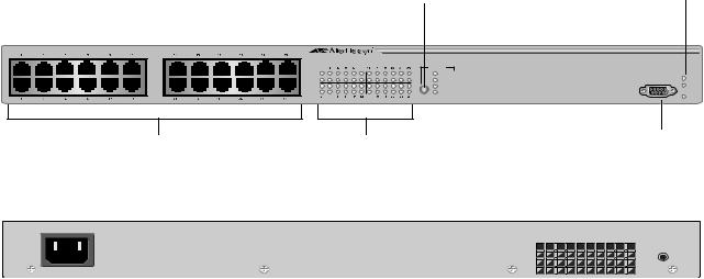
AT-8024 The AT-8024 is a 24-port 10/100Base-TX managed Fast Ethernet switch. The 10/100Base-TX twisted pair ports feature RJ-45 connectors and a maximum operating distance of 100 meters (328 feet). Refer to ”10/ 100Base-TX Twisted Pair Ports” on page 24 for additional information on the ports.
Figure 5 illustrates the front and back panels of the AT-8024 switch.
LED Mode |
System |
|
LEDs |
||
Select Button |
||
|
AT-8024 |
|
RS-232 TERMINAL PORT |
10Base-T / 100Base-TX Fast Ethernet Switch |
|
|
|
MODE |
|
Link |
COL |
|
Mode |
100 |
FAULT |
Link |
FULL |
MASTER |
Mode |
ACT |
|
|
|
PWR |
10/100Base-TX Ports Port LEDs RS-232 Terminal Port
RESET
|
|
|
|
|
|
|
|
|
|
|
|
|
|
|
|
|
|
|
|
|
|
|
|
|
|
|
|
|
|
|
|
|
|
|
|
|
|
|
|
|
|
|
|
|
|
|
|
|
|
|
|
|
|
|
|
|
|
|
|
|
|
|
|
|
|
|
|
|
AC Power |
|
|
|
|||||||||||||||||||
|
Reset |
|||||||||||||||||||||
Connector |
|
Button |
||||||||||||||||||||
Figure 5. AT-8024 Front and Back Panels
16
AT-8000 Series Fast Ethernet Switches Installation Guide
AT-8024GB The AT-8024GB is a 24-port 10/100Base-TX managed Fast Ethernet switch with two GBIC expansion slots. The GBIC expansion slots are compatible with fiber optic GBIC modules. The 10/100Base-TX twisted pair ports feature RJ-45 connectors with a maximum operating distance of 100 meters (328 feet). Refer to ”10/100Base-TX Twisted Pair Ports” on page 24 and ”Gigabit Interface Converter (GBIC) Expansion Slots” on page 28 for additional information.
Figure 6 illustrates the front and back panels of the AT-8024GB switch.
LED Mode Select Button |
System LEDs |
|
AT-8024GB
10Base-T / 100Base-TX Fast Ethernet Switch
Link 
Mode 
Link 
Mode 
|
CLASS 1 |
|
RS-232 TERMINAL PORT |
|
|
LASER PRODUCT |
|
||
|
DO NOT STARE |
|
|
|
|
INTO BEAM |
|
|
|
MODE |
PORT A |
PORT B |
|
|
COL |
|
|
|
|
100 |
LINK |
|
FAULT |
|
LINK |
|
|||
FULL |
MASTER |
|||
|
|
|||
ACT |
|
|
|
|
|
MODE |
MODE |
PWR |
|
|
|
10/100Base-TX Ports |
Port LEDs |
GBIC Expansion |
RS-232 |
|
Terminal Port |
||||
|
|
Slots |
||
|
|
|
|
RESET |
AC Power |
Reset |
Connector |
Button |
Figure 6. AT-8024GB Front and Back Panels
17
Overview
AT-8024M The AT-8024M is a 24-port 10/100Base-TX managed Fast Ethernet switch with two module expansion slots. The expansion slots are compatible with 100Base and 1000Base fiber optic and twisted pair port expansion modules and the AT-STACKM stacking module. The 10/100Base-TX twisted pair ports feature RJ-45 connectors with a maximum operating distance of 100 meters (328 feet). Refer to ”10/100Base-TX Twisted Pair Ports” on page 24 and ”Module Expansion Slots” on page 29 for additional information.
Figure 7 illustrates the front and back panels of the AT-8024M switch.
LED Mode |
System |
|
LEDs |
||
Select Button |
||
|
|
1 |
3 |
5 |
7 |
9 |
11 |
25 |
26 |
|
|
|
|
|
|
2 |
4 |
6 |
8 |
10 |
12 |
13 |
15 |
17 |
19 |
21 |
23 |
14 |
16 |
18 |
20 |
22 |
24 |
AT-8024M |
|
|
|
|
|
|
|
|
|
MODE |
RS-232 TERMINAL PORT STATUS |
||
10Base-T / 100Base-TX Fast Ethernet Switch |
|
|
|
|
|
COL |
|
||||||
1 |
3 |
5 |
7 |
9 |
11 |
13 |
15 |
17 |
19 |
21 |
23 |
100 |
|
LINK |
|
|
|
|
|
|
|
|
|
|
|
FULL |
FAULT |
MODE |
|
|
|
|
|
|
|
|
|
|
|
ACT |
MASTER |
|
|
|
|
|
|
|
|
|
|
|
|
||
LINK |
|
|
|
|
|
|
|
|
|
|
|
|
RPS |
MODE |
|
|
|
|
|
|
|
|
|
|
|
|
PWR |
2 |
4 |
6 |
8 |
10 |
12 |
14 |
16 |
18 |
20 |
22 |
24 |
|
|
Module Expansion Slots |
10/100Base-TX Ports |
|
|
|
Port LEDs |
|
|
|
|
|
RS-232 |
||||||||||||||||||||||
|
|
|
|
|
|
|
|
|
|
|
|
|
|
|
|
|
|
|
|
|
|
|
|
|
|
|
Terminal Port |
||||||
|
|
|
|
|
|
|
|
|
|
|
|
|
|
|
|
|
|
|
|
|
|
|
|
|
|
|
|
|
|
|
|
|
|
|
|
|
|
|
|
|
|
|
|
|
|
|
|
|
|
|
|
|
|
|
|
|
|
|
|
|
|
|
|
|
|
|
|
|
|
|
|
|
|
|
|
|
|
|
|
|
|
|
|
|
|
|
|
|
|
|
|
|
|
|
|
|
|
|
|
|
|
|
|
|
|
|
|
|
|
|
|
|
|
|
|
|
|
|
|
|
|
|
|
|
|
|
|
|
|
|
|
|
|
|
|
|
|
|
|
|
|
|
|
|
|
|
|
|
|
|
|
|
|
|
|
|
|
|
|
|
|
|
|
|
|
|
|
|
|
|
|
|
|
|
|
|
|
|
|
|
|
|
|
|
|
|
|
|
|
|
|
|
|
|
|
|
|
|
|
|
|
|
|
AC Power |
RPS |
Connector |
Connector |
Figure 7. AT-8024M Front and Back Panels
18
AT-8000 Series Fast Ethernet Switches Installation Guide
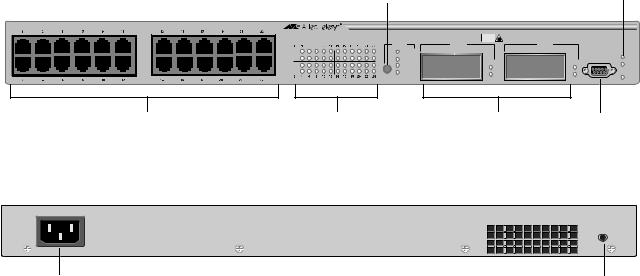
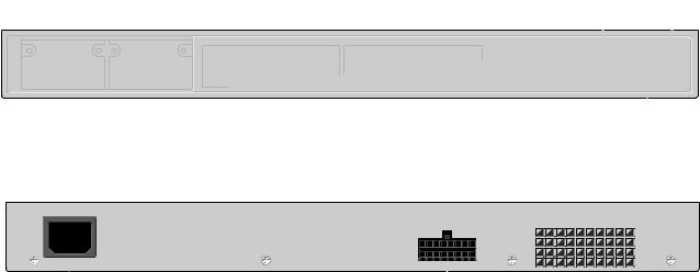
AT-8026FC The AT-8026FC is a 24-port 10/100Base-TX ports and two-port 100BaseFX managed Fast Ethernet switch. The 100Base-FX fiber optic ports feature SC connectors and a maximum operating distance of up to 2 kilometers (1.24 miles) or 412 meters (1,360 feet), depending on the duplex mode. The 10/100Base-TX twisted pair ports feature RJ-45 connectors and a maximum operating distance of 100 meters (328 feet). Refer to ”100Base-FX Fiber Optic Ports” on page 23 and ”10/100Base-TX Twisted Pair Ports” on page 24 for additional information.
Figure 8 illustrates the front and back panel of the AT-8026FC switch.
LED Mode Select Button |
System LEDs |
|
AT-8026FC |
|
10Base-T / 100Base-TX Fast Ethernet Switch |
|
|
MODE |
Link |
COL |
Mode |
100 |
Link |
FULL |
Mode |
ACT |
CLASS 1
LASER PRODUCT
DO NOT STARE
INTO BEAM
25 |
26 |
LINK |
TX |
RX |
MODE |
TX |
RX |
RS-232 TERMINAL PORT
 FAULT
FAULT
LINK |
MASTER |
PWR
MODE
10/100Base-TX Ports |
Port LEDs |
100Base-FX |
RS-232 |
|
|
Fiber Optic Ports |
Terminal Port |
|
RESET |
AC Power |
Reset |
Connector |
Button |
Figure 8. AT-8026FC Front and Back Panels
19

Overview
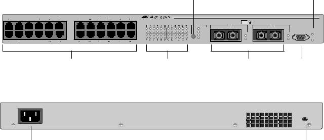
AT-8026T The AT-8026T switch has 24 10/100Base-TX ports and two twisted pair 10/100/1000Base-T ports. The Gigabit ports feature RJ-45 connectors with a maximum operating distance of 100 meters (328 feet). The 10/ 100Base-TX twisted pair ports features RJ-45 connectors with a maximum operating distance of 100 meters (328 feet). Refer to ”10/ 100Base-TX Twisted Pair Ports” on page 24 and ”10/100/1000Base-T Twisted Pair Ports” on page 26 for further information.
Figure 9 illustrates the front and back panels of the AT-8026T switch.
|
|
|
|
|
|
|
|
|
|
|
|
|
|
|
|
LED Mode Select Button |
|
System LEDs |
||||||||
|
|
|
|
|
|
|
|
|
|
|
|
|
|
|
|
|
|
|||||||||
1 |
3 |
5 |
7 |
9 |
11 |
13 |
15 |
17 |
19 |
21 |
23 |
|
|
|
|
|
|
|
|
|
|
|
|
|
|
|
|
|
|
|
|
|
|
|
|
|
|
|
AT-8026T |
|
|
|
|
|
|
|
|
|
|
|
RS-232 TERMINAL PORT |
||
|
|
|
|
|
|
|
|
|
|
|
|
10Base-T / 100Base-TX Fast Ethernet Switch with 10/100/1000Base-T Uplinks |
|
|
|
|||||||||||
|
|
|
|
|
|
|
|
|
|
|
|
1 |
3 |
5 |
7 |
9 |
11 |
13 |
15 |
17 |
19 |
21 |
23 MODE |
25 |
26 |
STATUS |
|
|
|
|
|
|
|
|
|
|
|
|
LINK |
|
|
|
|
|
|
|
|
|
|
COL |
10 |
10 |
FAULT |
|
|
|
|
|
|
|
|
|
|
|
|
MODE |
|
|
|
|
|
|
|
|
|
|
100 |
1000 LINK |
1000 |
LINK |
|
|
|
|
|
|
|
|
|
|
|
|
|
|
|
|
|
|
|
|
|
|
100 |
100 |
MASTER |
||
|
|
|
|
|
|
|
|
|
|
|
|
LINK |
|
|
|
|
|
|
|
|
|
|
FULL |
FULL |
FULL |
|
|
|
|
|
|
|
|
|
|
|
|
|
MODE |
|
|
|
|
|
|
|
|
|
|
ACT |
ACT |
ACT |
PWR |
2 |
4 |
6 |
8 |
10 |
12 |
14 |
16 |
18 |
20 |
22 |
24 |
2 |
4 |
6 |
8 |
10 |
12 |
14 |
16 |
18 |
20 |
22 |
24 |
10/100/1000BASE-T |
10/100/1000BASE-T |
|
|
|
|
|
10/100Base-TX Ports |
|
|
|
|
|
Port LEDs |
|
|
10/100/1000Base-T |
RS-232 |
||||||||||||
|
|
|
|
|
|
|
|
|
|
|
|
|
|
|
|
|
|
|
|
|
|
|
|
Ports |
|
Terminal Port |
|
|
|
|
|
|
|
|
|
|
|
|
|
|
|
|
|
|
|
|
|
|
|
|
|
|
RESET |
|
AC Power |
|
|
|
|
|
|
|
|
|
|
|
|
|
|
|
|
|
|
|
|
|
|
Reset |
||
|
Connector |
|
|
|
|
|
|
|
|
|
|
|
|
|
|
|
|
|
|
|
|
|
|
Button |
||
Figure 9. AT-8026T Front and Back Panels
20
AT-8000 Series Fast Ethernet Switches Installation Guide
AT-8088/xx The AT-8088/MT and AT-8088/SC switches have eight 10/100Base-TX ports and eight 100Base-FX ports with two module expansion slots. The expansion slots are compatible with 100Base and 1000Base fiber optic and twisted pair port expansion modules and the AT-STACKM stacking module. The 100Base-FX fiber optic ports feature MT-RJ or SC connectors with a maximum operating distance of 2 kilometers (1.24 miles), depending on the duplex mode. The 10/100Base-TX twisted pair ports feature RJ-45 connectors with a maximum operating distance of 100 meters (328 feet). Refer to ”100Base-FX Fiber Optic Ports” on page 23, ”10/100Base-TX Twisted Pair Ports” on page 24, and ”Gigabit Interface Converter (GBIC) Expansion Slots” on page 28 for more information.
Figure 10 and Figure 11 illustrate the front and back panels of the
AT-8088/xx switches.
AT-8088/MT |
|
|
|
|
|
10/100Base-TX Ports |
|
|
|
|
|
|
System |
|||||
|
|
|
|
|
|
|
|
|
|
|
LEDs |
|||||||
|
|
|
|
|
|
|
|
|
|
|
|
|||||||
|
|
1 |
|
2 |
|
3 |
|
4 |
|
5 |
|
6 |
|
7 |
|
8 |
|
|
|
|
L /A |
|
L /A |
|
L /A |
|
L /A |
|
L /A |
|
L /A |
|
L /A |
|
L /A AT-8088/MT |
|
|
|
|
|
|
|
|
|
|
|
|
|
|
|
|
|
|
|
8 Port 10Base-T/ 100Base-TX |
|
|
|
D/C |
|
D/C |
|
D/C |
|
D/C |
|
D/C |
|
D/C |
|
D/C |
|
D/C 8 Port 100Base-FX Fast Ethernet Switch |
STATUS |
|
|
|
|
|
|
|
|
|
|
|
|
|
|
|
|
|
|
|
|
17 |
18 |
|
|
|
PORT ACTIVITY |
L /A LINK / ACTIVITY |
D/C FULL DUP HALF DUP/ |
COL |
|
|
|
|
|
RS-232 TERMINAL PORT FAULT |
||||
|
|
L /A |
|
L /A |
|
L /A |
|
L /A |
|
L /A |
|
L /A |
|
L /A |
|
L /A |
|
MASTER |
|
|
|
|
|
|
|
|
|
|
|
|
|
|
|
|
|
|
|
|
|
|
|
|
|
|
|
|
|
|
|
|
|
|
|
|
|
RPS |
|
|
|
|
|
|
|
|
|
|
|
|
|
|
|
|
|
|
PWR |
|
9 |
D/C |
10 |
D/C |
11 |
D/C |
12 |
D/C |
13 |
D/C |
14 |
D/C |
15 |
D/C |
16 |
D/C |
|
|
|
|
|
|
|
|
|
|
|
|
|
||||||||
Module Expansion Slots |
|
|
|
|
|
|
100Base-FX Ports |
|
|
|
|
|
|
RS-232 |
|
|||
|
|
|
|
|
|
|
|
|
|
|
|
|
|
|
|
|
|
|
|
|
|
|
|
|
|
|
|
|
|
|
|
|
|
|
|
Terminal Port |
|
|
|
|
|
|
|
10/100Base-TX Ports |
|
|
|
|
|
|
System |
|||||
AT-8088/SC |
|
|
|
|
|
|
|
|
|
|
|
LEDs |
||||||
|
1 |
2 |
3 |
4 |
5 |
6 |
7 |
8 |
|
L /A |
L /A |
L /A |
L /A |
L /A |
L /A |
L /A |
L /A |
|
D/C |
D/C |
D/C |
D/C |
D/C |
D/C |
D/C |
D/C |
17 |
18 |
|
PORT ACTIVITY |
L /A LINK / ACTIVITY |
D/C FULL DUP HALF DUP/ |
COL |
|
|
|
|
|
L /A |
|
|
|
L /A |
|
|
|
L /A |
|
|
|
L /A |
|
|
|
L /A |
|
|
|
L /A |
|
|
|
L /A |
|
|
|
L /A |
TX |
9 |
RX |
D/C |
TX |
10 |
RX |
D/C |
TX |
11 |
RX |
D/C |
TX |
12 |
RX |
D/C |
TX |
13 |
RX |
D/C |
TX |
14 |
RX |
D/C |
TX |
15 |
RX |
D/C |
TX |
16 |
RX |
D/C |
AT-8088/SC
8 Port 10Base-T/ 100Base-TX
8 Port 100Base-FX Fast Ethernet Switch STATUS
 RS-232 TERMINAL PORT
 FAULT
FAULT
 MASTER
 RPS
RPS  PWR
PWR
Module Expansion Slots |
100Base-FX Ports |
RS-232 |
|
|
|
|
|
Terminal Port |
Figure 10. AT-8088/xx Front Panels
|
|
|
|
|
|
|
|
|
|
|
|
|
|
|
|
|
|
|
|
|
|
|
|
|
|
|
|
|
|
|
|
|
|
|
|
|
|
|
|
|
|
|
|
|
|
|
|
|
|
|
|
|
|
|
|
|
|
|
|
|
|
|
|
|
|
|
|
|
|
|
|
|
|
|
|
|
|
|
|
|
|
|
|
|
|
|
|
|
|
|
|
|
|
|
|
|
|
|
|
|
|
|
|
|
|
|
|
|
|
|
|
|
|
|
|
|
|
|
|
|
|
|
|
|
|
|
|
|
|
|
|
|
|
|
|
|
|
|
|
|
|
|
|
|
|
|
|
|
|
|
|
|
|
|
|
|
|
|
|
|
|
|
|
|
|
|
|
|
|
|
|
|
|
|
|
|
|
|
|
|
|
|
|
|
|
|
|
|
|
|
|
|
|
|
|
|
|
|
|
|
|
|
|
|
|
|
|
|
|
AC Power |
|
|
|
RPS |
|
|||||||||||||||||||||||||||||
Connector |
Connector |
|
||||||||||||||||||||||||||||||||
|
|
|
Figure 11. |
AT-8088/xx (MT and SC) Back Panel |
|
|||||||||||||||||||||||||||||
21

Overview
Hardware Features
The following sections describe these hardware features of the AT-8000
Series Fast Ethernet Switches:
”100Base-FX Fiber Optic Ports” on page 23
”10/100Base-TX Twisted Pair Ports” on page 24
”10/100/1000Base-T Twisted Pair Ports” on page 26
”Gigabit Interface Converter (GBIC) Expansion Slots” on page 28
”Module Expansion Slots” on page 29
”Twisted Pair Port LEDs and the LED Mode Select Button” on page 30
”Fiber Optic Port LEDs” on page 32
”System LEDs” on page 34
”RS-232 Terminal Port” on page 35
”Reset Button” on page 36
”RPS Connector” on page 37
”AC Power Connector” on page 38
”DC Power Connector” on page 39
22

AT-8000 Series Fast Ethernet Switches Installation Guide
100Base-FX Fiber Optic Ports
|
The AT-8016F/MT, AT-8016F/SC, and AT-8016F/ST switches feature 16 |
|
fiber optic ports. The AT-8026FC switch have two fiber optic ports. The |
|
AT-8088/MT and AT-8088/SC switches have eight fiber optic ports. The |
|
operating characteristics of the fiber optic ports on all the switches are |
|
the same. |
Type of |
The fiber optic ports on the AT-8016F/SC, AT-8026FC, and AT-8088/SC |
Connector |
switches feature SC connectors. |
|
The fiber optic ports on the AT-8016F/ST switch features ST connectors. |
|
The fiber optic ports on the AT-8016F/MT and AT-8088/MT switches |
|
feature MT-RJ connectors. |
Speed |
The fiber optic ports have a fixed operating speed of 100 megabits per |
|
second (Mbps). The speed cannot be changed. |
Duplex Mode |
The fiber optic ports can operate in either halfor full-duplex mode. You |
|
can set the duplex mode manually or allow the switch to set it |
|
automatically through Auto-Negotiation. |
Maximum
Distance
Type of Cable
Each fiber optic port has a maximum operating distance of 2 kilometers (1.25 miles) when operating in full-duplex mode and 412 meters (1,360 feet) when operating in half-duplex mode.
The fiber optic ports can use either 50/125 or 62.5/125 micron multimode fiber optic cable.
Note
Do not use single-mode fiber optic cable with these ports.
23

Overview
10/100Base-TX Twisted Pair Ports
Type of
Connector
Speed
Duplex Mode
Maximum
Distance
The twisted pair ports featured on the AT-8000 Series Switch are described below.
All twisted pair ports feature 8-pin RJ-45 connectors. For the port pinouts, refer to ”RJ-45 Twisted Pair Port Pinouts” on page 85.
The twisted pair ports are 10/100Base-TX compliant and are capable of both 10 megabits per second (Mbps) and 100 Mbps speeds. You can set the port speed manually or, since the ports are IEEE 802.3u AutoNegotiation compliant, you can let the switch set each port’s speed automatically. With Auto-Negotiation, the switch automatically matches the highest possible common speed between each switch port and each end-node. For example, if an end-node is capable of only 10 Mbps, the switch sets the port connected to the end-node to 10 Mbps.
Note
Auto-Negotiation is activated as the default on all twisted pair ports on the switch. To deactivate Auto-Negotiation and set the speeds manually, refer to the AT-S39 Management Software User’s Guide.
Each twisted pair port on the switch can operate in either halfor fullduplex mode. The twisted pair ports are IEEE 802.3u-compliant and will Auto-Negotiate the duplex mode setting.
If desired, Auto-Negotiation on one or all of the switch ports can be disabled so that you can set the duplex mode manually through the switch’s management software.
Note
In order for a switch port to successfully Auto-Negotiate its duplex mode with an end-node, the end-node should also be using AutoNegotiation. Otherwise, a duplex mode mismatch can occur. A switch port, using Auto-Negotiation, will default to half-duplex if it detects that the end-node is not using Auto-Negotiation. This will result in a mismatch if the end-node is operating at a fixed duplex mode of full-duplex. Consequently, when connecting an end-node with a fixed duplex mode of full-duplex to a switch port, you should use the AT-S39 management software to disable Auto-Negotiation on the port and set the port speed and duplex mode manually.
Each twisted pair port has a maximum operating distance of 100 meters (328 feet).
24

AT-8000 Series Fast Ethernet Switches Installation Guide
Type of Cabling For 10 Mbps operation, Category 3 or better 100 ohm shielded or unshielded twisted pair cabling is required. For 100 Mbps operation, Category 5 or Enhanced Category 5 (5E) 100 ohm shielded or unshielded twisted pair cabling is required.
Auto MDI/
MDI-X
Port Pinouts
The twisted pair ports are auto-MDI/MDI-X. They automatically configure themselves as either MDI or MDI-X. This feature allows you to use a straight-through twisted pair cable to connect any type of network device to a switch port.
Note
Disabling Auto-Negotiation on a port also disables Auto MDI/MDI-X on the port. You must set the MDI/MDI-X manually through the management software, refer to the AT-S39 Management Software User’s Guide.
Refer to Table 9 on page 85 and Table 10 on page 85 for the port pinouts.
25

Overview
10/100/1000Base-T Twisted Pair Ports
Type of
Connector
Speed
The two twisted pair 10/100/1000Base-T ports featured on the AT-8026T are described below.
The ports have 8-pin RJ-45 connectors. The ports use four pins when operating at 10 or 100 Mbps and all eight pins when operating at 1000 Mbps.
The ports can operate at 10, 100, or 1000 Mbps. The speed is set automatically through Auto-Negotiation or you can set the speed manually through the management software.
Duplex Mode The ports can operate in either halfor full-duplex mode. The ports are IEEE 802.3u compliant and will Auto-Negotiate the duplex mode. If needed, Auto-Negotiation can be disabled so that you can set the duplex mode manually through the management software.
Note
In order for a switch port to successfully Auto-Negotiate its duplex mode with an end-node, the end-node should also be using AutoNegotiation. Otherwise, a duplex mode mismatch can occur. A switch port, using Auto-Negotiation, will default to half-duplex if it detects that the end-node is not using Auto-Negotiation. This will result in a mismatch if the end-node is operating at a fixed duplex mode of full-duplex. Consequently, when connecting an end-node with a fixed duplex mode of full-duplex to a switch port, you should use the AT-S39 management software to disable Auto-Negotiation on the port and set the port speed and duplex mode manually.
Maximum The ports have a maximum operating distance of 100 meters (328 feet).
Distance
Type of Cable For 10 Mbps, the port requires Category 3 or better 100 ohm shielded or unshielded twisted pair cabling. For 100 or 1000 Mbps operation, the ports require Category 5 or Enhanced Category 5 (5E) 100 ohm shielded or unshielded twisted pair cabling.
26

Auto MDI/
MDI-X
Port Pinouts
AT-8000 Series Fast Ethernet Switches Installation Guide
The ports are auto-MDI/MDI-X. They automatically configure themselves as either MDI or MDI-X. This feature allows you to use a straight-through twisted pair cable to connect any type of network device to a switch port.
Note
Disabling Auto-Negotiation on a port also disables Auto MDI/MDI-X on the port. You must set the MDI/MDI-X manually through the management software, refer to the AT-S39 Management Software User’s Guide.
For the pinouts of these ports when operating at 10 or 100 Mbps in the MDI configuration, refer to Table 9 on page 85. For the pinouts of the ports when operating at 10 or 100 Mbps in the MDI-X configuration, refer to Table 10 on page 85. For port pinouts when the ports are operating at 1000 Mbps, refer to Table 11 on page 86.
27
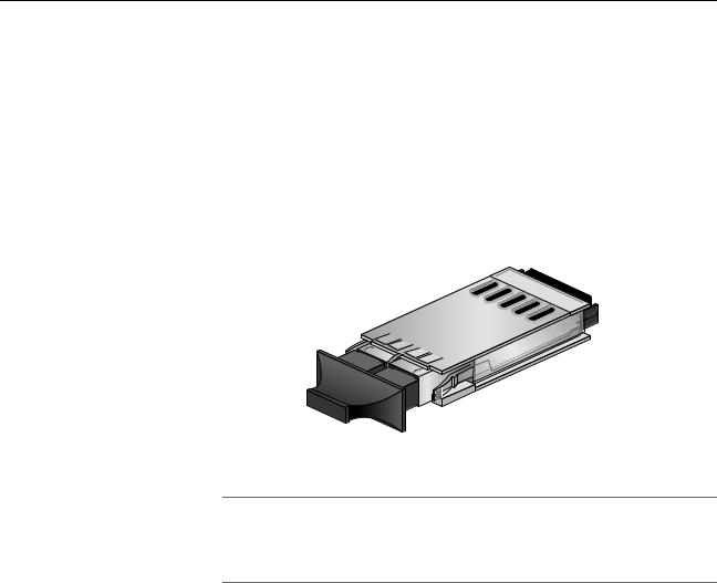
Overview
Gigabit Interface Converter (GBIC) Expansion Slots
The AT-8024GB Fast Ethernet Switch has two expansion slots on the front panel, labelled Port A and Port B, which correspond to Ports 25 and 26, respectfully. Each slot can accommodate one optional fiber optic Gigabit Interface Converter (GBIC) Ethernet module.
An GBIC module is a fast and easy way for you to add an 1000 Mbps fiber optic port to your Fast Ethernet switch. GBIC modules can be used to extend the distance of your network, build a high-speed backbone network between switches, or connect additional end-nodes to the network, such as high-speed servers.
Figure 12 shows an example of a fiber optic GBIC module.
Figure 12. GBIC Module
Note
For a list of the Allied Telesyn GBIC modules supported by the AT-8024GB Fast Ethernet Switch, contact your Allied Telesyn sales representative.
28

AT-8000 Series Fast Ethernet Switches Installation Guide
Module Expansion Slots
The AT-8016/xx, AT-8024M, and AT-8088/xx switches have two expansion slots. The AT-8012M and AT-8012M-QS have one expansion slot. Each slot can accommodate an expansion module. You can use the slots to add 100Base and 1000Base fiber optic and twisted pair ports to the switch.
Note
For a list of the Allied Telesyn expansion modules supported by the switches, contact your Allied Telesyn sales representative or refer to our website at: www.alliedtelesyn.com.
29

Overview
Twisted Pair Port LEDs and the LED Mode Select Button
The twisted pair port LEDs and the LED Mode Select button for the
AT-8000 Series Switches are describe below.
The port LEDs on the front panel display port status information. Each port has two LEDs. The Link LED indicates whether there is a valid link between a port and the end-node connected to it.
Each port also has a Mode LED. This LED displays a variety of status information, including port speed and duplex mode. You use the Mode Select button on the front panel to toggle the Mode LEDs to display different status information. The LEDs next to the Mode Select button indicate the status being displayed by the port Mode LEDs. For example, if the Mode 100 LED is green, then the port Mode LEDs are displaying port speed.
Note
Toggling the Mode Selection button does not affect the normal operations of the switch.
Table 2 describes the twisted pair port LEDs of the AT-8000 Series
Switches, except for the AT-8088/xx switch, which does not have a LED
Mode Select button.
Table 2. AT-8000 Series Twisted Pair Port LEDs
LED |
State |
Description |
|
|
|
|
|
|
LINK |
OFF |
Indicates that there is no link between the |
|
|
port and the end-node. |
|
|
|
|
Green |
Indicates a valid link has been established |
|
|
between the port and the end-node. |
|
|
|
Mode - COL |
OFF |
Indicates that no data collisions are |
|
|
occurring on the port. |
|
|
|
|
Flashing |
Indicates that data collisions are occurring |
|
Green |
on the port. |
|
|
|
Mode - 100 |
OFF |
Indicates that the port is operating at 10 |
|
|
Mbps. |
|
|
|
|
Green |
Indicates that the port is operating at 100 |
|
|
Mbps |
|
|
|
30
Loading...