


 Loading...
Allied Telesis AT-FS710-8, AT-FS710-8E, AT-FS710-5, AT-FS710-24, AT-FS710-16E User Manual
...
FS710 Series
Fast Ethernet Unmanaged Switch
AT-FS710/5
AT-FS710/5E
AT-FS710/8
AT-FS710/8E
AT-FS710/16
AT-FS710/16E
AT-FS710/24
Installation Guide
613-002436 Rev. A
Copyright 2017 Allied Telesis, Inc.
All rights reserved. No part of this publication may be reproduced without prior written permission from Allied Telesis, Inc.
Microsoft and Internet Explorer are registered trademarks of Microsoft Corporation. Netscape Navigator is a registered trademark of Netscape Communications Corporation. All other product names, company names, logos or other designations mentioned herein are trademarks or registered trademarks of their respective owners.
Allied Telesis, Inc. reserves the right to make changes in specifications and other information contained in this document without prior written notice. The information provided herein is subject to change without notice. In no event shall Allied Telesis, Inc. be liable for any incidental, special, indirect, or consequential damages whatsoever, including but not limited to lost profits, arising out of or related to this manual or the information contained herein, even if Allied Telesis, Inc. has been advised of, known, or should have known, the possibility of such damages.

Electrical Safety and Emissions
Standards
This product meets the following standards:
Federal Communications Commission Interference Statement
Declaration of Conformity (Class A)
Manufacturer Name: Allied Telesis, Inc.
Declares that the product: Fast Ethernet Unmanaged Switch
Model Numbers: AT-FS710/16, AT-FS710/16E and AT-FS710/24
U.S. Federal Communications Commission
Radiated Energy
Note: This equipment has been tested and found to comply with the limits for a Class A digital device pursuant to Part 15 of FCC Rules. These limits are designed to provide reasonable protection against harmful interference when the equipment is operated in a commercial environment. This equipment generates, uses, and can radiate radio frequency energy and, if not installed and used in accordance with this instruction manual, may cause harmful interference to radio communications. Operation of this equipment in a residential area is likely to cause harmful interference in which case the user will be required to correct the interference at his own expense.
Note: Modifications or changes not expressly approved of by the manufacturer or the FCC, can void your right to operate this equipment.
Industry Canada
This Class A digital apparatus complies with Canadian ICES-003.
Cet appareil numérique de la classe A est conforme à la norme NMB-003 du Canada.
European Union Restriction of the Use of Certain Hazardous Substances
(RoHS) in Electrical and Electronic Equipment
This Allied Telesis RoHS-compliant product conforms to the European Union Restriction of the Use of Certain Hazardous Substances (RoHS) in Electrical and Electronic Equipment. Allied Telesis ensures RoHS conformance by requiring supplier Declarations of Conformity, monitoring incoming materials, and maintaining manufacturing process controls.
Warning: In a domestic environment this product may cause radio interference in which case the user may be required to take adequate measures.
3
Declaration of Conformity (Class B)
Manufacturer Name: Allied Telesis, Inc.
Declares that the product: Fast Ethernet Unmanaged Switch
Model Number: AT-FS710/5, AT-FS710/5E, AT-FS710/8, and AT-FS710/8E
This device complies with Part 15 of the FCC Rules. Operation is subject to the following two conditions: (1) This device may not cause harmful interference, and (2) this device must accept any interference received, including interference that may cause undesired operation.
This equipment has been tested and found to comply with the limits for a Class B digital device, pursuant to Part 15 of the FCC Rules. These limits are designed to provide reasonable protection against harmful interference in a residential installation. This equipment generates, uses and can radiate radio frequency energy and, if not installed and used in accordance with the instructions, may cause harmful interference to radio communications. However, there is no guarantee that interference will not occur in a particular installation. If this equipment does cause harmful interference to radio or television reception, which can be determined by turning the equipment off and on, the user is encouraged to try to correct the interference by one of the following measures:
Reorient or relocate the receiving antenna.
Increase the separation between the equipment and receiver.
Connect the equipment into an outlet on a circuit different from that to which the receiver is connected.
Consult the dealer or an experienced radio/TV technician for help.
Caution
Any changes or modifications not expressly approved by the party responsible for compliance could void the user's authority to operate this equipment. E80
Avertissement
Les changements ou modifications non expressément approuvés par la partie responsable de la conformité pourraient annuler l'autorité de l'utilisateur à utiliser cet équipement. E80
Radiation Exposure Statement:
This equipment complies with FCC radiation exposure limits set forth for an uncontrolled environment. This equipment should be installed and operated with minimum distance 20cm between the radiator & your body.
European Union Restriction of the Use of Certain Hazardous Substances (RoHS) in Electrical and Electronic Equipment
RoHs compliant
European Union RoHS (Directive 2011/65/EU of the European Parliament and of the Council
4
of 8 June 2011 on the restriction of the use of certain hazardous substances in electrical and electronic equipment.)
This Allied Telesis RoHS-compliant product conforms to the European Union Restriction of the Use of Certain Hazardous Substances (RoHS) in Electrical and Electronic Equipment. Allied Telesis ensures RoHS conformance by requiring supplier Declarations of Conformity, monitoring incoming materials, and maintaining manufacturing process controls.
5

Safety and Electromagnetic Emissions Certificates
EMI Certifications
FCC Part 15 Class A for the AT-FS710/16, AT-FS710/16E and AT-FS710/24
FCC Part 15 Class B for the AT-FS710/5, AT-FS710/5E, AT-FS710/8, and AT-FS710/8E
VCCI Class A for the AT-FS710/16, AT-FS710/16E and AT-FS710/24
VCCI Class B for the AT-FS710/5, AT-FS710/5E, AT-FS710/8, and AT-FS710/8E
EN 55032 Class A for all models
EN 55024
Safety Certificates
UL 60950-1: 2014 2nd Edition
CSA c22.2 No 60950-1 2nd Edition, Oct. 2014
EN60950-1: 2006+A11+A1+A12+A2
Translated Safety Statements
Important: The indicates that a translation of the safety statement is available in a PDF document titled “Translated Safety Statements” on the Allied Telesis website at www.alliedtelesis.com/support.
6

Contents
Preface ................................................................................................................................................................................ |
12 |
Safety Symbols Used in this Document ........................................................................................................................ |
13 |
Contacting Allied Telesis ............................................................................................................................................... |
14 |
Chapter 1: Product Description ........................................................................................................................................ |
15 |
Overview ....................................................................................................................................................................... |
16 |
Front and Rear Panels ........................................................................................................................................... |
16 |
Key Features ................................................................................................................................................................. |
23 |
10/100Base-TX Twisted Pair Ports ........................................................................................................................ |
23 |
External Power Supply DC Power Connector........................................................................................................ |
24 |
System and Port LEDs........................................................................................................................................... |
24 |
Wall and Rack Mount Bracket Summary................................................................................................................ |
26 |
Ethernet Cable Specifications ................................................................................................................................ |
26 |
Ethernet Switching Basics............................................................................................................................................. |
27 |
Duplex Mode .......................................................................................................................................................... |
27 |
Store and Forward ................................................................................................................................................. |
27 |
Back Pressure and Flow Control............................................................................................................................ |
27 |
Chapter 2: Installation ....................................................................................................................................................... |
29 |
Reviewing Safety Precautions....................................................................................................................................... |
30 |
Selecting a Site for the Switch....................................................................................................................................... |
32 |
Unpacking the Switch.................................................................................................................................................... |
33 |
Installing the Switch on a Table or Desktop .................................................................................................................. |
34 |
Wall-Mounting the Switch.............................................................................................................................................. |
35 |
Guidelines for Installing the Switch on a Wall ........................................................................................................ |
35 |
AT-FS710/5 & 5E Wall Installation ......................................................................................................................... |
35 |
AT-FS710/8 & 8E Wall Installation ......................................................................................................................... |
40 |
AT-FS710/16, /16E & /24 Wall Installation............................................................................................................. |
44 |
Rack Mounting the Switch............................................................................................................................................. |
49 |
Guidelines for Installing the Switch in a Rack ........................................................................................................ |
49 |
Items Need for Rack Installation ............................................................................................................................ |
49 |
AT-FS710/8 & 8E Rack Mounting Installation........................................................................................................ |
50 |
AT-FS710/16, /16E & /24 Rack Mounting Installation............................................................................................ |
54 |
Powering On the Switch ................................................................................................................................................ |
56 |
Energizing Internal Power Supply Models.............................................................................................................. |
56 |
Energizing External AC/DC Power Supply Models ................................................................................................ |
58 |
Cabling the Switch......................................................................................................................................................... |
60 |
Chapter 3: Troubleshooting .............................................................................................................................................. |
61 |
Appendix A: Technical Specifications ............................................................................................................................. |
62 |
Physical Specifications.................................................................................................................................................. |
62 |
Environmental Specifications ........................................................................................................................................ |
63 |
Chassis Power Specifications ....................................................................................................................................... |
63 |
External Power Adapter Specifications ......................................................................................................................... |
63 |
RJ-45 Twisted Pair Port Connectors ............................................................................................................................. |
64 |
7
Contents
8

List of Figures
Figure 1: AT-FS710/5 Front Panel........................................................................................................................................ |
16 |
Figure 2: AT-FS710/5 Rear Panel ........................................................................................................................................ |
16 |
Figure 3: AT-FS710/5E Front Panel ..................................................................................................................................... |
17 |
Figure 4: AT-FS710/5E Rear Panel...................................................................................................................................... |
17 |
Figure 5: AT-FS710/8 Front Panel........................................................................................................................................ |
18 |
Figure 6: AT-FS710/8 Rear Panel ........................................................................................................................................ |
18 |
Figure 7: AT-FS710/8E Front Panel ..................................................................................................................................... |
19 |
Figure 8: AT-FS710/8E Rear Panel...................................................................................................................................... |
19 |
Figure 9: AT-FS710/16 Front Panel...................................................................................................................................... |
20 |
Figure 10: AT-FS710/16 Rear Panel .................................................................................................................................... |
20 |
Figure 11: AT-FS710/16E Front Panel ................................................................................................................................. |
21 |
Figure 12: AT-FS710/16E Rear Panel.................................................................................................................................. |
21 |
Figure 13: AT-FS710/24 Front Panel.................................................................................................................................... |
22 |
Figure 14: AT-FS710/24 Rear Panel .................................................................................................................................... |
22 |
Figure 15: Wall Mounting Hole Locations for Left Facing Ports............................................................................................ |
36 |
Figure 16: Wall Mounting Hole Locations for Up or Down Facing Ports............................................................................... |
37 |
Figure 17: Aligning and Securing an AT-FS710/5 or 5E Switch onto Wall Screws .............................................................. |
38 |
Figure 18: Removing the Rubber Feet ................................................................................................................................. |
41 |
Figure 19: Marking the Screw Hole Locations...................................................................................................................... |
42 |
Figure 20: Driving the Screws through the Holes ................................................................................................................. |
43 |
Figure 21: Placing the Switch into the Brackets ................................................................................................................... |
43 |
Figure 22: Removing FS710 Series Rubber Feet................................................................................................................. |
45 |
Figure 23: Marking the Screw Hole Locations...................................................................................................................... |
46 |
Figure 24: Attaching Brackets with Screws .......................................................................................................................... |
47 |
Figure 25: Placing the Switch into the Brackets ................................................................................................................... |
47 |
Figure 26: Marking the Screw Hole Locations for the Top Brackets..................................................................................... |
48 |
Figure 27: Attaching Handles to Brackets ............................................................................................................................ |
52 |
Figure 28: Attaching Brackets to Plates................................................................................................................................ |
52 |
Figure 29: Attaching Cable Tray to Plates............................................................................................................................ |
52 |
Figure 30: Attaching the Plates to the Switch....................................................................................................................... |
53 |
Figure 31: Attaching the Switch to Equipment Rack............................................................................................................. |
53 |
Figure 32: Removing FS710 Series Switch Rubber Feet..................................................................................................... |
54 |
Figure 33: Attaching Rack Mount Brackets to the Switch..................................................................................................... |
54 |
Figure 34: Attaching the Switch to Equipment Rack............................................................................................................. |
55 |
Figure 35: Plug Power Cord into Rear Panel AC Connector................................................................................................ |
56 |
Figure 36: Plug AC Power Cord in to AC Outlet................................................................................................................... |
57 |
Figure 37: Package Contents ............................................................................................................................................... |
58 |
Figure 38: Slide AC Plug Into AC/DC Power Adapter .......................................................................................................... |
58 |
Figure 39: Plug Power Cord into Rear Panel DC Connector................................................................................................ |
59 |
Figure 40: RJ-45 Connector and Port Pin Layout................................................................................................................. |
64 |
9
Figures
10
List of Tables
Table 1: AT-FS710/5, AT-FS710/5E, AT-FS710/8 and AT-FS710/8E System and Port LEDs .......................................... |
24 |
Table 2: AT-FS710/16, AT-FS710/16E and AT-FS710/24 System and Port LEDs ............................................................. |
25 |
Table 3: Wall and Rack Mount Brackets .............................................................................................................................. |
26 |
Table 4: Twisted Pair Cabling and Distances ...................................................................................................................... |
26 |
Table 5: Model vs Wall Mount Kit ........................................................................................................................................ |
35 |
Table 6: List of Components in the AT-BRKT-J23 Wall Mount Kit ...................................................................................... |
40 |
Table 7: List of Components in the AT-BRKT-J22 Wall Mount Kit ...................................................................................... |
44 |
Table 8: Model vs Rack Mount Kit ....................................................................................................................................... |
49 |
Table 9: List of Components in the AT-RKMT-J08 Rack Mount Kit ..................................................................................... |
50 |
Table 10: Physical Dimensions (W x D x H) ........................................................................................................................ |
62 |
Table 11: Product Weight .................................................................................................................................................... |
62 |
Table 12: Environmental Specifications ............................................................................................................................... |
63 |
Table 13: Chassis Input Power Specifications ..................................................................................................................... |
63 |
Table 14: AC/DC Power Adapter Specifications .................................................................................................................. |
63 |
Table 15: MDI Pin Signals (10Base-T or 100Base-TX) ....................................................................................................... |
64 |
Table 16: MDI-X Pin Signals (10Base-T or 100Base-TX) ................................................................................................... |
64 |
11

Preface
This manual is the installation and user’s guide for the FS710 Series switches. This Preface contains the following sections:
“Safety Symbols Used in this Document” on page 13
“Contacting Allied Telesis” on page 14
12

FS710 Series Ehternet Switch Installation Guide
Safety Symbols Used in this Document
This document uses the following conventions:
Note
Notes provide additional information.
Caution
Cautions inform you that performing or omitting a specific action may result in equipment damage or loss of data.
Warning
Warnings inform you that performing or omitting a specific action may result in bodily injury.
13

Contacting Allied Telesis
If you need assistance with this product, you may contact Allied Telesis technical support by going to the Support & Services section of the Allied Telesis web site at alliedtelesis.com/support. You can find links for the following services on this page:
24/7 Online Support - Enter our interactive support center to search for answers to your questions in our knowledge database, check support tickets, learn about Return Merchandise Authorization (RMA), and contact Allied Telesis technical experts.
USA and EMEA phone support - Select the phone number that best fits your location and customer type.
Hardware warranty information - Learn about Allied Telesis warranties and register your product online.
Replacement Services - Submit an RMA request via our interactive support center.
Documentation - View the most recent installation guides, user guides, software release notes, white papers and data sheets for your product.
Software Updates - Download the latest software releases for your product.
For sales or corporate contact information, go to alliedtelesis.com/ purchase and select your region.
14

Chapter 1
Product Description
This chapter contains the follows sections:
“Overview” on page 16
“Key Features” on page 23
“Ethernet Switching Basics” on page 27
15
Overview
Front and Rear
Panels
The FS710 Series switches provides a simple solution for Ethernet switching between devices operating at either 10 Mbps or 100 Mbps and include the following switch models:
–AT-FS710/5
–AT-FS710/5E
–AT-FS710/8
–AT-FS710/8E
–AT-FS710/16
–AT-FS710/16E
–AT-FS710/24
The FS710 Series switches are designed to be used on a desktop or mounted on a wall. The switch does not require software configuration or management.
The front and rear panels for each switch model are as follows:
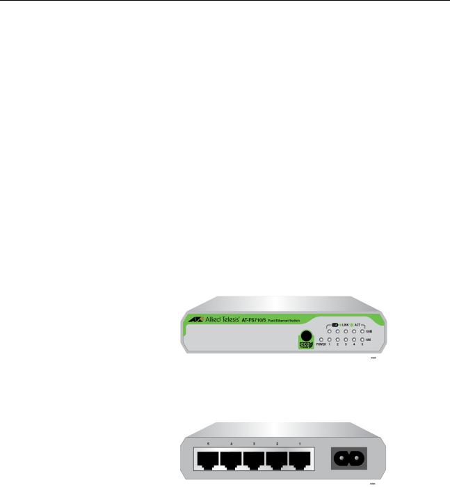
Figure 1 illustrates the AT-FS710/5 front panel.
Figure 1. AT-FS710/5 Front Panel
Figure 2 illustrates the AT-FS710/5 rear panel.
x
Figure 2. AT-FS710/5 Rear Panel
16

FS710 Series Ehternet Switch Installation Guide
Figure 3 illustrates the AT-FS710/5E front panel.
Figure 3. AT-FS710/5E Front Panel
Figure 4 illustrates the AT-FS710/5E rear panel.
x
Figure 4. AT-FS710/5E Rear Panel
17

Figure 5 illustrates the AT-FS710/8 front panel.
Figure 5. AT-FS710/8 Front Panel Figure 6 illustrates the AT-FS710/8 rear panel.
x
100-240VAC~
4398
Figure 6. AT-FS710/8 Rear Panel
18
FS710 Series Ehternet Switch Installation Guide
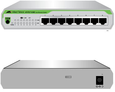
Figure 7 illustrates the AT-FS710/8E front panel.
x
Figure 7. AT-FS710/8E Front Panel
Figure 8 illustrates the AT-FS710/8E rear panel.
x
5VDC |
– |
|
4397
Figure 8. AT-FS710/8E Rear Panel
19
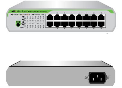
Figure 9 illustrates the AT-FS710/16 front panel.
x
Figure 9. AT-FS710/16 Front Panel Figure 10 illustrates the AT-FS710/16 rear panel.
x
100-240VAC~ |
4398 |
Figure 10. AT-FS710/16 Rear Panel
20
Loading...