


 Loading...
Fast Ethernet
Switch
AT-8326GB
K
Installation
Guide
PN 613-50282-00 Rev A
Copyright Ó 2002 Allied Telesyn, Inc.
960 Stewart Drive Suite B, Sunnyvale, CA 94085 USA
All rights reserved. No part of this publication may be reproduced without prior written permission from Allied Telesyn, Inc.
All other product names, company names, logos or other designations mentioned herein are trademarks or registered trademarks of their respective owners.
Allied Telesyn, Inc. reserves the right to make changes in specifications and other information contained in this document without prior written notice. The information provided herein is subject to change without notice. In no event shall Allied Telesyn, Inc. be liable for any incidental, special, indirect, or consequential damages whatsoever, including but not limited to lost profits, arising out of or related to this manual or the information contained herein, even if Allied Telesyn, Inc. has been advised of, known, or should have known, the possibility of such damages.

Electrical Safety and Emission
Statement
Standards: This product meets the following standards.
U.S. Federal Communications Commission
RADIATED ENERGY
Note: This equipment has been tested and found to comply with the limits for a Class A digital device pursuant to Part 15 of the FCC Rules. These limits are designed to provide reasonable protection against harmful interference when the equipment is operated in a commercial environment. This equipment generates, uses, and can radiate radio frequency energy and, if not installed and used in accordance with this instruction manual, may cause harmful interference to radio communications. Operation of this equipment in a residential area is likely to cause harmful interference in which case the user will be required to correct the interference at his own expense.
Note: Modifications or changes not expressly approved by the manufacturer or the FCC can void your right to operate this equipment.
Canadian Department of Communications
This Class A digital apparatus meets all requirements of the Canadian Interference-Causing Equipment Regulations.
Cet appareil numérique de la classe A respecte toutes les exigences du Règlement sur le matériel brouilleur du Canada.
RFI Emission |
FCC Class A, EN55022 Class A, CISPR22 Class A (VCCI), AS/NZS3548 (C- |
|
TICK), EN61000-3-2, EN61000-3-3 1 |
Warning: In a domestic environment this product may cause radio interference in which case the user may be required to take adequate measures. 2
Immunity |
EN55024 3 |
Electrical Safety |
UL 1950 (UL/cUL)), EN60950 4 |
Laser |
EN60825 5 |
Important: Appendix C contains translated safety statements for installing this equipment. When you see the , go to Appendix C for the translated safety statement in your language.
Wichtig: Anhang C enthält übersetzte Sicherheitshinweise für die Installation dieses Geräts. Wenn Sie sehen, schlagen Sie in Anhang C den übersetzten Sicherheitshinweis in Ihrer Sprache nach.
Vigtigt: Tillæg C indeholder oversatte sikkerhedsadvarsler, der vedrører installation af dette udstyr. Når De ser symbolet , skal De slå op i tillæg C og finde de oversatte sikkerhedsadvarsler i Deres eget sprog.
Belangrijk: Appendix C bevat vertaalde veiligheidsopmerkingen voor het installeren van deze apparatuur. Wanneer u de ziet, raadpleeg Appendix C voor vertaalde veiligheidsinstructies in uw taal.
Important : L'annexe C contient les instructions de sécurité relatives à l'installation de cet équipement. Lorsque vous voyez le symbole , reportez-vous à l'annexe C pour consulter la traduction de ces instructions dans votre langue.
Tärkeää: Liite C sisältää tämän laitteen asentamiseen liittyvät käännetyt turvaohjeet. Kun näet -symbolin, katso käännettyä turvaohjetta liitteestä C.
Importante: l’Appendice C contiene avvisi di sicurezza tradotti per l’installazione di questa apparecchiatura. Il simbolo , indica di consultare l’Appendice C per l’avviso di sicurezza nella propria lingua.
Viktig: Tillegg C inneholder oversatt sikkerhetsinformasjon for installering av dette utstyret. Når du ser , åpner du til Tillegg C for å finne den oversatte sikkerhetsinformasjonen på ønsket språk.
Importante: O Anexo C contém advertências de segurança traduzidas para instalar este equipamento. Quando vir o símbolo , leia a advertência de segurança traduzida no seu idioma no Anexo C.
Importante: El Apéndice C contiene mensajes de seguridad traducidos para la instalación de este equipo. Cuando vea el símbolo, vaya al Apéndice C para ver el mensaje de seguridad traducido a su idioma.
Obs! Bilaga C innehåller översatta säkerhetsmeddelanden avseende installationen av denna utrustning. När du ser , skall du gå till Bilaga C för att läsa det översatta säkerhetsmeddelandet på ditt språk.
iii

Table of Contents
Preface ...................................................................................................................................................................................................................... |
6 |
How This Guide is Organized ............................................................................................................................................................................. |
6 |
Document Conventions ...................................................................................................................................................................................... |
7 |
Where to Find Web-based Guides ................................................................................................................................................................... |
8 |
Contacting Allied Telesyn ................................................................................................................................................................................... |
9 |
Telephone Support ....................................................................................................................................................................................... |
9 |
For Sales or Corporate Information ........................................................................................................................................................ |
9 |
Management Software Updates .................................................................................................................................................................... |
10 |
Chapter 1 |
|
Product Description ......................................................................................................................................................................................... |
11 |
Summary of Features .......................................................................................................................................................................................... |
11 |
Location of Components ................................................................................................................................................................................... |
12 |
Hardware Features .............................................................................................................................................................................................. |
13 |
Twisted Pair Ports........................................................................................................................................................................................ |
13 |
Gigabit Interface Converter (GBIC) Slots............................................................................................................................................. |
17 |
Stacking Ports ............................................................................................................................................................................................... |
18 |
System LEDs .................................................................................................................................................................................................. |
19 |
Stack ID LEDs................................................................................................................................................................................................. |
20 |
10/100 Mbps Port LEDs ............................................................................................................................................................................. |
21 |
10/100/1000 Mbps Port LEDs.................................................................................................................................................................. |
22 |
Gigabit Connector LEDs............................................................................................................................................................................ |
23 |
RS-232 Terminal Port.................................................................................................................................................................................. |
24 |
AC Power Connector.................................................................................................................................................................................. |
25 |
Software Features ................................................................................................................................................................................................ |
26 |
AT-S41 Management Software .............................................................................................................................................................. |
26 |
Spanning Tree Protocol (STP) ................................................................................................................................................................. |
29 |
Tagged and Port-based VLANs............................................................................................................................................................... |
30 |
Quality of Service (QoS)............................................................................................................................................................................. |
30 |
IGMP Snooping ............................................................................................................................................................................................ |
31 |
Dynamic Host Configuration Protocol (DHCP)................................................................................................................................. |
32 |
Port Monitoring............................................................................................................................................................................................ |
32 |
Port Trunking ................................................................................................................................................................................................ |
32 |
Port Security .................................................................................................................................................................................................. |
35 |
A Few Basics to Ethernet Switching .............................................................................................................................................................. |
36 |
MAC Address Table..................................................................................................................................................................................... |
36 |
Duplex Mode................................................................................................................................................................................................. |
37 |
Store and Forward....................................................................................................................................................................................... |
37 |
4
Backpressure and Flow Control ............................................................................................................................................................. |
37 |
Network Topologies ............................................................................................................................................................................................ |
39 |
Power Workgroup Topology................................................................................................................................................................... |
39 |
Collapsed Backbone - Hub Topology................................................................................................................................................... |
40 |
Switch Stacking Topology........................................................................................................................................................................ |
41 |
Chapter 2 |
|
Installation ............................................................................................................................................................................................................ |
42 |
Installation Safety Precautions ........................................................................................................................................................................ |
43 |
Selecting a Site for the Switch ......................................................................................................................................................................... |
44 |
Required Cables .................................................................................................................................................................................................... |
45 |
Unpacking the Switch ........................................................................................................................................................................................ |
46 |
Installing the Switch on a Desktop ................................................................................................................................................................ |
47 |
Installing the Switch in a Rack ......................................................................................................................................................................... |
48 |
Installing an Optional GBIC Module .............................................................................................................................................................. |
50 |
Creating a Switch Stack ..................................................................................................................................................................................... |
52 |
Cabling the Switch ............................................................................................................................................................................................... |
55 |
Powering On the Switch .................................................................................................................................................................................... |
58 |
Starting a Local Management Session ......................................................................................................................................................... |
59 |
Warranty Registration ......................................................................................................................................................................................... |
62 |
Chapter 3 |
|
Troubleshooting ................................................................................................................................................................................................ |
63 |
Appendix A |
|
Technical Specifications ................................................................................................................................................................................. |
67 |
Physical Specifications ....................................................................................................................................................................................... |
67 |
Environmental Specifications .......................................................................................................................................................................... |
67 |
Power Specifications ........................................................................................................................................................................................... |
67 |
Safety and Electromagnetic Emissions Certifications ............................................................................................................................. |
68 |
Standards ................................................................................................................................................................................................................ |
68 |
SNMP Support ....................................................................................................................................................................................................... |
68 |
Appendix B |
|
Default Switch Settings .................................................................................................................................................................................. |
69 |
Appendix C |
|
Translated Electrical Safety and Emission Information .................................................................................................................. |
71 |
5

Preface
This guide contains instructions on how to install the stackable
AT-8326GB Fast Ethernet switch.
How This Guide is Organized
This manual contains the following chapters and appendices:
Chapter 1, Hardware Description, describes the features and components of the switch.
Chapter 2, Installation, contains the installation instructions.
Chapter 3, Troubleshooting, provides information on how to resolve common problems that might occur with the switch.
Appendix A, Technical Specifications, contains the switch’s technical specifications.
Appendix B, Switch Default Settings, lists the factory default settings.
Appendix C, Translated Electrical Safety and Emission Information, contains translations of the warnings and cautions in the manual.
6
AT-8326GB Installation Guide
Document Conventions
This document uses the following conventions to highlight important information.
Note
Notes provide additional information.
Warning
Warnings inform you that performing or omitting a specific action may result in bodily injury.
 Caution
Cautions inform you that performing or omitting a specific action may result in equipment damage or loss of data.
7

AT-8326GB Installation Guide
Where to Find Web-based Guides
The Allied Telesyn web site at www.alliedtelesyn.com contains the most recent documentation for all Allied Telesyn International products. All documents are available as PDF files. You can either view the documents online or download them onto a local workstation or server.
Once you have installed the switch, refer to following manual for instructions on how to manage and configure the unit. The manual is available from the Allied Telesyn web site:
AT-S41 Management Software User’s Guide
PN 613-50283-00
8

AT-8326GB Installation Guide
Contacting Allied Telesyn
Telephone
Support
To contact Technical Support by telephone, find your country or region in the table below.
United States and Canada |
Europe, Africa, and the Middle |
||
Tel: |
1 800 428 4835 (option 4) |
East |
|
|
|
Tel: |
00 800 287 877 67* or |
|
|
|
+31 20 711 4333 |
|
|
(Finland only: Tel: 990 287 877 67) |
|
|
|
||
Asia and Southeast Asia |
Australia |
||
Tel: |
(++65) 381 5612 |
Tel: |
1 800 000 880 |
|
|
|
|
New Zealand |
|
|
|
Tel: |
0800 45 5782 |
|
|
|
|
|
|
For Sales or Corporate Information
(* Valid in Austria, Belgium, France, Germany, Ireland, Italy, Luxembourg, The Netherlands, Norway, Sweden, Switzerland and the United Kingdom. For other European countries not listed here, ring +31 20 711 4333.)
You can also contact Technical Support online at: http://kb.alliedtelesyn.com
Allied Telesyn, Inc.
19800 North Creek Parkway,
Suite 200
Bothell, WA 98011
Tel: (425) 487-8880
Fax: (425) 489-9191
9

AT-8326GB Installation Guide
Management Software Updates
Allied Telesyn periodically updates the management software programs for our managed products. To obtain a copy of an updated management program, you can download the software either from our web site or our FTP server at ftp.alliedtelesyn.com. To use the FTP server, enter ‘anonymous’ for the user name when you log in and your e-mail address for the password.
10
Chapter 1
Product Description
The AT-8326GB is a stackable Layer 2 Fast Ethernet switch. It offers a wide range of features and capabilities, all designed to simplify the task of creating and maintaining a Fast Ethernet network.
Summary of Features
G24 10/100Base-TX ports with RJ-45 connectors
GTwo 10/100/1000Base-T ports with RJ-45 connectors
GAuto-MDI/MDI-X on all twisted pair ports
GAuto-Negotiation for speed and duplex mode (IEEE 803.3ucompliant)
GTwo slots for Gigabit Interface Converter modules
GTwo stacking ports
GPort trunking and port monitoring
GPort security
GDynamic Host Configuration Protocol
GInternet Group Management Protocol snooping
GAT-S41 management software
GPort-based and tagged VLANs (IEEE 802.1Q-compliant)
GSpanning tree protocol (IEEE 802.1d-compliant)
GQuality of Service (IEEE 802.1p-compliant)
11
AT-8326GB Installation Guide
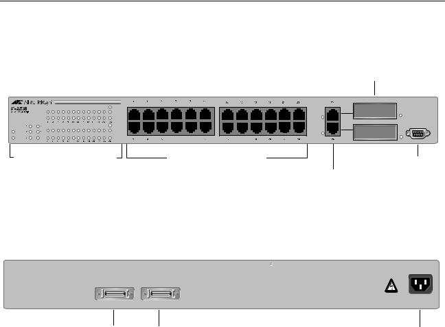
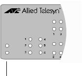
Location of Components
Figure 1 illustrates the front panel of the AT-8326GB Fast Ethernet
Switch.
|
|
|
GBICSlots |
|
GIGA |
|
|
|
LNK/ACT |
|
|
|
FDX/COL |
|
|
|
STACK ID |
|
RS-232 |
|
GIGA |
|
|
FAULT |
LNK/ACT |
|
|
|
|
|
|
PWR |
FDX/COL |
|
|
System and Port LEDs |
10/100Base-TX Ports |
RS232 |
|
|
|
|
|
|
|
|
10/100/1000Base-T Ports Terminal Port |
Figure 1 AT-8326GB Front Panel
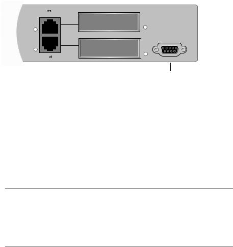
Figure 2 illustrates the back panel.
STACK IN STACK OUT
100-240 VAC
Stacking Ports AC Power Connector
Figure 2 Back Panel
12

AT-8326GB Installation Guide
Hardware Features
The following sections describe these hardware features of the AT8326GB Fast Ethernet switch:
|
G 10/100Base-TX and 10/100/1000Base-T Ports |
||||||
|
G Gigabit Interface Converter (GBIC) Slots |
||||||
|
G Stacking Ports |
||||||
|
G System LEDs |
||||||
|
G Stack ID LEDs |
||||||
|
G Port LEDs |
||||||
|
G Gigabit Connector LEDs |
||||||
|
G RS-232 Terminal Port |
||||||
|
G AC Power Connector |
||||||
Twisted Pair |
|
|
|
|
|
|
|
Ports |
|
|
10/100/1000Base-T Ports |
||||
|
|
|
|
|
|
|
|
|
|
|
|
|
|
|
|
|
|
|
|
|
|
|
|
|
|
|
|
|
|
|
|
|
|
|
|
|
|
|
|
10/100Base-TX Ports
Figure 3 Twisted Pair Ports
The AT-8326GB Fast Ethernet switch features 24 10/100 Mbps twisted pair ports and two 10/100/1000 Mbps twisted pair ports. The features of the twisted pair ports are described below.
Type of Connector
All of the twisted pair ports feature RJ-45 connectors. (For the port pinout details, refer to RJ-45 Port Pinouts on page 15.)
Speed
The 10/100Base-TX ports are capable of 10 megabits per second (Mbps) or 100 Mbps speeds. The 10/100/1000Base-TX ports are capable of 10 Mbps, 100 Mbps, or 1000 Mbps speeds. You can set the port speed manually or, since the ports are IEEE 802.3u Auto-Negotiation compliant, you can allow the switch to set each port’s speed automatically. With
13

AT-8326GB Installation Guide
Auto-Negotiation, the switch automatically matches the highest possible common speed between each switch port and each end node. For example, if an end node is capable of only 10 Mbps, the switch sets the port connected to the end node to 10 Mbps.
Note
Auto-Negotiation is activated as the default on all of the ports on the switch. To deactivate Auto-Negotiation and set the speeds manually, refer to the AT-S41 Management Software User’s Guide.
Maximum Distance
Each twisted pair port has a maximum operating distance of 100 m (328 ft).
Type of Cabling
For 10 Mbps operation, Category 3 or better 100 ohm shielded or unshielded twisted pair cabling is required. For 100 or 1000 Mbps operation, Category 5 and Enhanced Category 5 (5E) 100 ohm shielded or unshielded twisted pair cabling is required.
Auto-MDI
All of the twisted pair ports on the switch are auto-MDI and IEEE 802.3ab-compatible. They automatically configure themselves as either MDI or MDI-X. This feature allows you to use either straight-through or cross-over twisted pair cables to connect devices to the ports.
Duplex Mode
Each twisted pair port on the switch can operate in either halfor fullduplex mode. The twisted pair ports are IEEE 802.3u-compliant and will Auto-Negotiate the duplex mode setting. If the end node connected to a twisted pair port on the switch is capable of full-duplex operation, the switch sets the port to full-duplex. If the end node is capable of only halfduplex, the port is set to half-duplex.
If desired, Auto-Negotiation on one or all of the twisted pair ports can be disabled so that you can set the duplex mode manually through the switch’s management software.
14
AT-8326GB Installation Guide
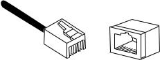
RJ-45 Port Pinouts
Figure 4 illustrates the pin layout to an RJ-45 connector and port.
1 |
8 |
8 |
|
1 |
Figure 4 RJ-45 Connector and Port Pin Layout
Table 1 lists the RJ-45 pin signals when a twisted pair port is operating in the MDI configuration.
|
Table 1 MDI Pin Signals (10/100 Mbps) |
|
|
|
|
Pin |
|
Signal |
|
|
|
|
|
|
1 |
|
TX+ |
|
|
|
2 |
|
TX- |
|
|
|
3 |
|
RX+ |
|
|
|
6 |
|
RX- |
|
|
|
Table 2 lists the RJ-45 port pin signals when a twisted pair port is operating in the MDI-X configuration.
|
Table 2 MDI-X Pin Signals (10/100 Mbps) |
|
|
|
|
Pin |
|
Signal |
|
|
|
|
|
|
1 |
|
RX+ |
|
|
|
2 |
|
RX- |
|
|
|
3 |
|
TX+ |
|
|
|
6 |
|
TX- |
|
|
|
15
AT-8326GB Installation Guide
Table 3 lists the RJ-45 connector pins and their signals when a 10/100/ 1000 Mbps twisted pair port is operating at 1000 Mbps.
Table 3 1000 Mbps Pin Signals
Pin |
Pair |
Signal |
|
|
|
|
|
|
1 |
1 |
TX and RX+ |
|
|
|
2 |
1 |
TX and RX- |
|
|
|
3 |
2 |
TX and RX+ |
|
|
|
4 |
2 |
TX and RX+ |
|
|
|
5 |
3 |
TX and RX- |
|
|
|
6 |
3 |
TX and RX- |
|
|
|
7 |
4 |
TX and RX+ |
|
|
|
8 |
4 |
TX and RX- |
|
|
|
16
AT-8326GB Installation Guide
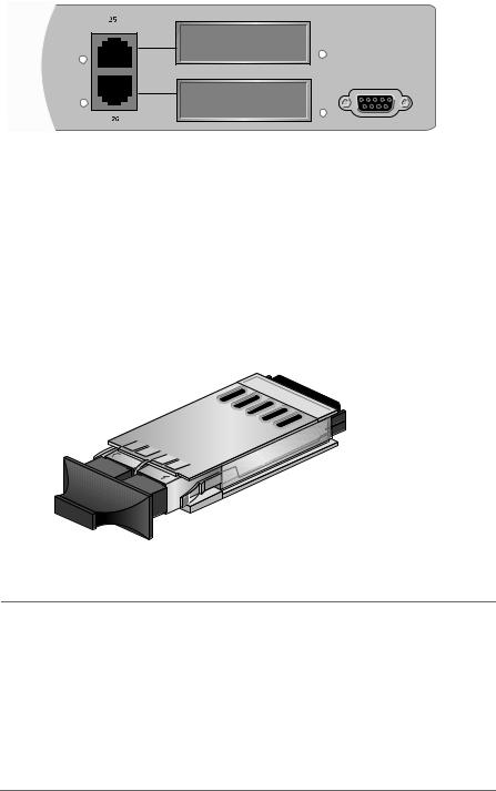
Gigabit
Interface
Converter
(GBIC) Slots
RS-232
Figure 5 GBIC Slots
The AT-8326GB Fast Ethernet switch has two GBIC slots on the front panel, which correspond to Ports 25 and 26. Each slot can accommodate one optional GBIC module.
A GBIC module is a gigabit (1000Base) transceiver. GBIC modules can be used to extend the distance of your network, build a high-speed backbone network, or connect additional nodes to the network, such as high-speed servers. Figure 6 shows an example of a fiber optic GBIC module.
Figure 6 Example of a GBIC Module
Note
Ports 25 and 26 can each support only one medium type (i.e., twisted pair or GBIC) at a time. For example, if you install a GBIC for Port 25, you cannot use the corresponding twisted pair port.
In order to use Port 25 or 26 with a GBIC module, you must change the port setting in the management software to GBIC instead of twisted pair. For instructions, refer to the AT-S41 Management Software User’s Guide.
The AT-8326GB Gigabit Ethernet Switch supports the AT-G8 series GBIC modules: SX, LX, LX25, LX40, LX75.
17

AT-8326GB Installation Guide
Stacking Ports
STACK IN |
STACK OUT |
 Stacking Ports
Figure 7 Stacking Ports
There are two stacking ports on the back of the switch (Figure 7). The ports are used to connect AT-8326GB switches to form a logical switch. A logical switch consists of two or more individual switches that function as one unit. This feature offers the following benefits:
GStacking allows you to build a switch that is customized to the needs and requirements of your network.
GStacking simplifies network management. Rather than having to mange the switches individually, you can manage all of the switches as one unit.
GStacking allows you to manage multiple switches from one management session. All of the switches in a stack can be managed from one management session through the master switch of the switch stack.
GStacking switches reduces the number of IP addresses you need to assign to the switches you want to manage, since you can use one IP address for all of the switches in a switch stack.
Up to six AT-8326GB switches can be stacked together in a daisy-chain stacking configuration. Star and redundant path configurations will not work.
A stack does not require any additional hardware other than the switches and the LVDS stacking cable that comes with the units.
18
AT-8326GB Installation Guide
System LEDs
AT-8326GB
24 + 2G Managed Switch
STACK ID
FAULT
PWR
|
|
System LEDs |
|
|
Figure 8 System LEDs |
|
The system LEDs on the front panel display general status information |
|
|
about the entire switch. The system LEDs are defined in Table 4. |
|
|
|
Table 4 System LEDs |
|
|
|
LED |
State |
Description |
|
|
|
|
|
|
PWR |
Green |
System power is ON. |
|
|
|
|
OFF |
System power is OFF. |
|
|
|
FAULT |
Green |
The switch or management software has malfunctioned. |
|
|
(Refer to Chapter 3, Troubleshooting on page 60 for |
|
|
instructions on how to determine and repair the problem.) |
|
|
|
|
Flashing |
The switch is loading its operating software, running |
|
Green |
diagnostic tests, writing messages to FLASH, or |
|
|
downloading files using XMODEM. |
|
|
|
19

AT-8326GB Installation Guide
Stack ID LEDs
AT-8326GB |
GIGA |
|
LNK/ACT |
||
24 + 2G Managed Switch |
||
|
FDX/COL |
|
|
STACK ID |
|
|
GIGA |
|
FAULT |
LNK/ACT |
|
|
||
PWR |
FDX/COL |
Stack ID LEDs
Figure 9 Stack ID LEDs
The stack ID LEDs indicate the switch’s position in a switch stack. Since you can stack up to six AT-8326GB switches, there are six stack ID LEDs. For instructions on how to create a switch stack, refer to Creating a Switch Stack on page 52.
20
AT-8326GB Installation Guide
10/100 Mbps
Port LEDs
AT-8326GB |
GIGA |
|
LNK/ACT |
||
24 + 2G Managed Switch |
||
|
FDX/COL |
|
|
STACK ID |
|
|
GIGA |
|
FAULT |
LNK/ACT |
|
|
||
PWR |
FDX/COL |
Port LEDs
Figure 10 Port LEDs
The 10/100 Mbps port LEDs on the front panel display port status information for Ports 1-24. Each 10/100 Mbps port has two LEDs.
Each port has a LNK/ACT LED which displays the speed of an established link and whether or not there is any activity on the link.
Each port also has an FDX/COL LED. This LED displays the duplex mode of the port and whether or not there are any collisions occurring on the port.
Table 5 describes the 10/100Base-TX port LEDs.
Table 5 10/100 Mbps Port LEDs
LED |
State |
Description |
|
|
|
|
|
|
LNK/ACT |
Steady Green |
A 100 Mbps link with no activity. |
|
|
|
|
Flashing Green |
A 100 Mbps link with activity. |
|
|
|
|
Steady Yellow |
A 10 Mbps link with no activity. |
|
|
|
|
Flashing Yellow |
A 10 Mbps link with activity. |
|
|
|
|
OFF |
No link has been established. |
|
|
|
FDX/COL |
Green |
The port is in full-duplex mode. |
|
|
|
|
Yellow |
The port is in half-duplex mode and no data colli- |
|
|
sions are occurring on the port. |
|
|
|
|
Flashing Yellow |
The port is in half-duplex mode with collisions. |
|
|
|
21
AT-8326GB Installation Guide
10/100/1000 Mbps Port LEDs
The 10/100/1000 Mbps port LEDs on the front panel display port status information for Ports 25 and 26. Each 10/100/1000 Mbps port has three LEDs.
Like the 10/100 Mbps ports, the 10/100/1000Mbps ports have the same LNK/ACT and FDX/COL LEDs that display status information when the port is operating at 10/100 Mbps speeds. The 10/100/1000 Mbps ports have an additional LED called the GIGA LED that displays the LNK/ACT status information when the port is operating at 1000 Mbps speeds.
Table 6 describes the 10/100/1000 Mbps port LEDs.
Table 6 10/100/1000 Mbps Port LEDs
LED |
State |
Description |
|
|
|
|
|
|
GIGA |
Steady Green |
A 1000 Mbps link with no activity. |
|
|
|
|
Flashing Green |
A 1000 Mbps link with activity. |
|
|
|
|
OFF |
No 1000 Mbps link has been established. |
|
|
|
LNK/ACT |
Steady Green |
A 100 Mbps link with no activity. |
|
|
|
|
Flashing Green |
A 100 Mbps link with activity. |
|
|
|
|
Steady Yellow |
A 10 Mbps link with no activity. |
|
|
|
|
Flashing Yellow |
A 10 Mbps link with activity. |
|
|
|
|
OFF |
No 10/100 Mbps link has been established. |
|
|
|
FDX/COL |
Green |
The port is in full-duplex mode. |
|
|
|
|
Yellow |
The port is in half-duplex mode and no data colli- |
|
|
sions are occurring on the port. |
|
|
|
|
Flashing Yellow |
The port is in half-duplex mode with collisions. |
|
|
|
22

AT-8326GB Installation Guide
Gigabit
Connector LEDs
RS-232 |
Connector LEDs
Figure 11 Gigabit Connector LEDs
Ports 25 and 26 each have two connector LEDs on the front panel that indicate which connector type is being used for each port: the RJ-45 or the GBIC. The connector LEDs for each port are located to the left of the RJ-45 connectors and to the right of the GBIC slots.
23
AT-8326GB Installation Guide
RS-232
Terminal Port
RS-232
Terminal Port
Figure 12 RS-232 Terminal Port
The RS-232 Terminal Port is used to establish a local (out-of-band) management session with the switch. Using the port, you can access the switch’s management software and configure the switch’s operating parameters.
You establish a local management session by connecting either a VT100 terminal or a personal computer with a terminal emulation program to the port.
Note
You are not required to manage an AT-8326GB Fast Ethernet switch. The default switch settings may be sufficient for your network, in which case you can use the unit as an unmanaged switch. For the switch’s default settings, refer to Default Switch Settings on page 69.
The RS-232 Terminal Port has a DB-9 female connector and uses a null modem management cable.
The default settings for the RS-232 Terminal Port are:
GEmulation mode: VT100
GData rate: 9600
GData bits: 8
GParity: None
GStop bits: 1
GFlow control: None
G Key mode: Terminal
24
AT-8326GB Installation Guide
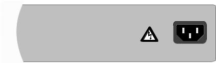
AC Power
Connector
100-240 VAC
Figure 13 AC Power Connector
The switch has a single AC power supply socket on the back panel, which has autoswitch AC inputs. Refer to the Technical Specifications on page 67 for the input voltage range. To power ON or OFF the switch, you connect or disconnect the power cord.
25
Loading...