


 Loading...
AT-MC1008/GB AT-MC1008/SP
Gigabit Media Converters
Installation Guide
PN 613-50654-00 Rev B
Copyright © 2005 Allied Telesyn, Inc. www.alliedtelesyn.com
All rights reserved. No part of this publication may be reproduced without prior written permission from Allied Telesyn, Inc.
Ethernet is a registered trademark of Xerox Corporation. All other product names, company names, logos or other designations mentioned herein are trademarks or registered trademarks of their respective owners.
Allied Telesyn, Inc. reserves the right to make changes in specifications and other information contained in this document without prior written notice. The information provided herein is subject to change without notice. In no event shall Allied Telesyn, Inc. be liable for any incidental, special, indirect, or consequential damages whatsoever, including but not limited to lost profits, arising out of or related to this manual or the information contained herein, even if Allied Telesyn, Inc. has been advised of, known, or should have known, the possibility of such damages.

Electrical Safety and Emission
Compliance Statement
Standards: This product meets the following standards.
U.S. Federal Communications Commission
Declaration of Conformity
Radiated Energy
Note: This equipment has been tested and found to comply with the limits for a Class A digital device pursuant to Part 15 of FCC Rules. These limits are designed to provide reasonable protection against harmful interference when the equipment is operated in a commercial environment. This equipment generates, uses, and can radiate radio frequency energy and, if not installed and used in accordance with this instruction manual, may cause harmful interference to radio communications. Operation of this equipment in a residential area is likely to cause harmful interference in which case the user will be required to correct the interference at his own expense.
Note: Modifications or changes not expressly approved of by the manufacturer or the FCC, can void your right to operate this equipment.
Industry Canada
This Class A digital apparatus meets all requirements of the Canadian Interference-Causing Equipment Regulations.
Cet appareil numérique de la classe A respecte toutes les exigences du Règlement sur le matériel brouilleur du Canada.
RFI Emissions |
FCC Class A, EN55022 Class A, |
|
C-TICK, CE |
Immunity |
EN55024 |
Electrical Safety |
EN60950 (TUV), UL 60950 (CULUS) |
Laser Safety |
EN60825 |
Warning: Class 1 Laser product. 1
Warning: Do not stare into the Laser beam. 2
3
Electrical Safety and Emission Compliance Statement
Important: Appendix C contains translated safety statements for installing this equipment. When you see the , go to Appendix C for the translated safety statement in your language.
Wichtig: Anhang C enthält übersetzte Sicherheitshinweise für die Installation dieses Geräts. Wenn Sie sehen, schlagen Sie in Anhang C den übersetzten Sicherheitshinweis in Ihrer Sprache nach.
Importante: El Apéndice C contiene mensajes de seguridad traducidos para la instalación de este equipo. Cuando vea el símbolo , vaya al Apéndice C para ver el mensaje de seguridad traducido a su idioma.
Important : L'annexe C contient les instructions de sécurité relatives à l'installation de cet équipement. Lorsque vous voyez le symbole , reportez-vous à l'annexe C pour consulter la traduction de ces instructions dans votre langue.
Importante: I’Appendice C contiene avvisi di sicurezza tradotti per l’installazione di questa apparecchiatura. Il simbolo , indica di consultare l’Appendice C per l’avviso di sicurezza nella propria lingua.
Важно: Приложение C содержит переведенную инструкцию по безопасности при установке данного устройства. Если Вы встретите , перейдите к Приложению C для получения переведенной инструкции по безопасности.
4

Contents
Electrical Safety and Emission Compliance Statement ................................. |
3 |
Preface ................................................................................................................ |
9 |
Safety Symbols Used in this Document............................................................. |
10 |
Where to Find Web-based Guides..................................................................... |
11 |
Contacting Allied Telesyn................................................................................... |
12 |
Online Support............................................................................................ |
12 |
Email and Telephone Support .................................................................... |
12 |
Returning Products ..................................................................................... |
12 |
Sales or Corporate Information................................................................... |
12 |
Management Software Updates ................................................................. |
12 |
Chapter 1 |
|
Overview ........................................................................................................... |
13 |
Introduction ........................................................................................................ |
14 |
AT-MC1008/GB Media Converter............................................................... |
14 |
AT-MC1008/SP Media Converter ............................................................... |
15 |
Key Features...................................................................................................... |
16 |
1000Base-TX Twisted Pair Port......................................................................... |
17 |
Type of Connector ...................................................................................... |
17 |
Port Speed.................................................................................................. |
17 |
Duplex Mode............................................................................................... |
17 |
Maximum Distance ..................................................................................... |
17 |
Type of Cabling........................................................................................... |
17 |
Auto MDI/MDI-X.......................................................................................... |
18 |
Port Pinouts ................................................................................................ |
18 |
1000Base Fiber Optic GBIC Slot on the AT-MC1008/GB Converter ................. |
19 |
1000Base Fiber Optic SFP Slot on the AT-MC1008/SP Converter ................... |
20 |
MODE Push Button............................................................................................ |
21 |
Link Test ..................................................................................................... |
21 |
MissingLink ................................................................................................. |
21 |
Smart MissingLink....................................................................................... |
22 |
5
Contents |
|
LEDs .................................................................................................................. |
23 |
Status LED.................................................................................................. |
23 |
Twisted pair port LEDs................................................................................ |
24 |
Fiber Optic Port LEDs (GBIC or SFP Expansion Slot)................................ |
24 |
MODE push button LEDs............................................................................ |
25 |
12VDC Power Supply ........................................................................................ |
26 |
Network Topologies ........................................................................................... |
27 |
Standalone Topology.................................................................................. |
27 |
Back-to-Back Topology............................................................................... |
28 |
Chapter 2 |
|
Installing the Media Converter........................................................................ |
29 |
Verifying Package Contents............................................................................... |
30 |
Planning the Installation..................................................................................... |
31 |
Selecting a Site........................................................................................... |
32 |
Reviewing Safety Guidelines ...................................................................... |
32 |
Installing a GBIC Transceiver ............................................................................ |
35 |
Installing an SFP Transceiver ............................................................................ |
37 |
Installing an AT-MC1008 Series Converter on a Desktop ................................. |
39 |
Installing the Media Converter in the AT-MCR12 Chassis................................. |
40 |
Cabling the Media Converter ............................................................................. |
42 |
Connecting to the GBIC Transceiver on the AT-MC1008/GB |
|
Media Converter ......................................................................................... |
42 |
Connecting to the SFP Transceiver on the AT-MC1008/SP |
|
Media Converter ......................................................................................... |
44 |
Connecting to the Copper Port ................................................................... |
46 |
Powering On the Media Converter..................................................................... |
47 |
Warranty Registration ........................................................................................ |
49 |
Chapter 3 |
|
Troubleshooting............................................................................................... |
51 |
Appendix A |
|
Technical Specifications ................................................................................. |
53 |
Physical.............................................................................................................. |
53 |
Temperature....................................................................................................... |
53 |
Electrical Rating ................................................................................................. |
53 |
Agency Certifications ......................................................................................... |
54 |
RJ-45 Twisted Pair Port Pinouts ........................................................................ |
54 |
6
AT-MC1008 Series Installation Guide |
|
Appendix B |
|
Cleaning Fiber Optic Connectors................................................................... |
55 |
Using a Cartridge-Type Cleaner ........................................................................ |
56 |
Using a Swab..................................................................................................... |
58 |
Appendix C |
|
Translated Electrical, Safety, and Emission Information............................. |
61 |
7

Preface
This guide contains instructions on how to install the AT-MC1008 Series Gigabit Media Converter and contains the following sections:
“Safety Symbols Used in this Document” on page 10
“Where to Find Web-based Guides” on page 11
“Contacting Allied Telesyn” on page 12
9

Preface
Safety Symbols Used in this Document
This document uses the safety symbols defined in Table 1.
|
|
Table 1. Safety Symbols |
|
|
|
|
|
Symbol |
Meaning |
|
Description |
|
|
|
|
|
|
|
|
|
Caution |
|
Performing or omitting a specific action may |
|
|
|
result in equipment damage or loss of data. |
|
|
|
|
|
Warning |
|
Performing or omitting a specific action may |
|
|
|
result in electrical shock. |
|
|
|
|
10
AT-MC1008 Series Installation Guide
Where to Find Web-based Guides
The installation and user guides for all Allied Telesyn products are available in portable document format (PDF) on our web site at www.alliedtelesyn.com. You can view the documents online or download them onto a local workstation or server.
11

Preface
Contacting Allied Telesyn
This section provides Allied Telesyn contact information for technical support as well as sales and corporate information.
Online Support
You can request technical support online by accessing the Allied Telesyn Knowledge Base: http://kb.alliedtelesyn.com. You can use the Knowledge Base to submit questions to our technical support staff and review answers to previously asked questions.
Email and Telephone Support
For Technical Support via email or telephone, refer to the Support & Services section of the Allied Telesyn web site: www.alliedtelesyn.com.
Returning Products
Products for return or repair must first be assigned a return materials authorization (RMA) number. A product sent to Allied Telesyn without an RMA number will be returned to the sender at the sender’s expense.
To obtain an RMA number, contact Allied Telesyn Technical Support through our web site: www.alliedtelesyn.com.
Sales or Corporate Information
You can contact Allied Telesyn for sales or corporate information through our web site: www.alliedtelesyn.com. To find the contact information for your country, select Contact Us -> Worldwide Contacts.
Management Software Updates
New releases of management software for our managed products are available from either of the following Internet sites:
Allied Telesyn web site: www.alliedtelesyn.com
Allied Telesyn FTP server: ftp://ftp.alliedtelesyn.com
If you prefer to download new software from the Allied Telesyn FTP server from your workstation’s command prompt, you will need FTP client software and you must log in to the server. Enter “anonymous” for the user name and your email address for the password.
12

Chapter 1
Overview
The AT-MC1008 Series Media Converters are Gigabit Ethernet bridging converters. They offer a wide range of features and capabilities designed to simplify the task of creating or expanding a Gigabit Ethernet network.
The models in the AT-MC1008 Series are:
AT-MC1008/GB
AT-MC1008/SP
This chapter contains the following sections:
“Introduction” on page 14
“Key Features” on page 16
“1000Base-TX Twisted Pair Port” on page 17
“1000Base Fiber Optic GBIC Slot on the AT-MC1008/GB Converter” on page 19
“1000Base Fiber Optic SFP Slot on the AT-MC1008/SP Converter” on page 20
“LEDs” on page 23
“MODE Push Button” on page 21
“12VDC Power Supply” on page 26
“Network Topologies” on page 27
13
Chapter 1: Overview
Introduction
The AT-MC1008/GB is a 1000Base-TX copper to GBIC (Gigabit Interface Connector) media converter. The AT-MC1008/SP is a 1000Base-TX copper to SFP (Small Form-factor Pluggable) media converter.
The AT-MC1008 Series Media Converters are designed for both standalone and rackmount use (in an AT-MCR12 chassis) and do not require software configuration or management.
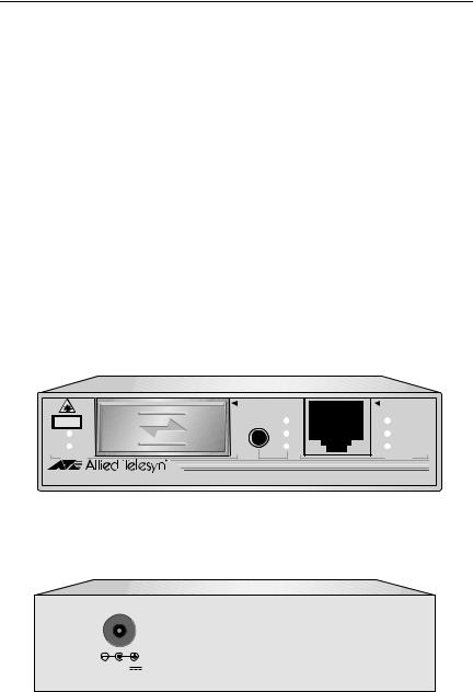
AT-MC1008/GB Media Converter
The AT-MC1008/GB media converter features:
One 1000Base-TX twisted pair port
One 1000Base GBIC pluggable port
One MODE push button for Link Test (LT), MissingLinkTM (ML), and Smart MissingLink (SML) modes
Eight LEDs for system and port status
One DC receptacle power adapter
Figure 1 illustrates the front panel of the AT-MC1008/GB converter.
|
1000Base |
|
1000Base-T |
CLASS 1 |
MODE |
ML |
PWR |
LASER PRODUCT |
|||
LINK |
|
SML |
LINK |
ACT |
|
LT |
ACT |
PORT 1 |
|
|
PORT 2 |
AT-MC1008/GB GIGABIT ETHERNET MEDIA CONVERTER |
AUTO MDI/MDI-X |
||
|
|
|
357 |
Figure 1. AT-MC1008/GB Front Panel
Figure 2 illustrates the back panel of the AT-MC1008/GB converter.
12VDC |
359 |
Figure 2. AT-MC1008/GB Back Panel
14

AT-MC1008 Series Installation Guide
AT-MC1008/SP Media Converter
The AT-MC1008/SP media converter features:
One 1000Base-TX twisted pair port
One 1000Base SFP pluggable port
One push button for Link Test (LT), MissingLink (ML), and Smart MissingLink (SML) modes
Eight LEDs for system and port status
One DC receptacle power adapter
Figure 3 illustrates the front panel of the AT-MC1008/SP media converter.
1000Base-T
SFP
|
|
|
|
|
|
|
|
|
|
1000Base |
MODE |
ML |
|
|
PWR |
||||
|
|
|
|
|
|
|
|
|
|
|
|
|
|||||||
|
|
LINK |
|
|
|
|
|
SML |
|
|
LINK |
||||||||
|
|
|
CLASS 1 |
|
|
|
|
|
|
|
|
|
|
|
|||||
|
|
ACT |
LASER PRODUCT |
|
|
|
|
LT |
|
|
ACT |
||||||||
|
|
|
|
|
|
|
|
|
|||||||||||
|
|
PORT 1 |
|
|
|
|
|
|
|
|
PORT 2 |
|
|
||||||
|
|
|
|
|
|
|
|
|
|||||||||||
|
|
|
|
|
|
|
|
|
|
|
|
|
|
|
|
|
|
|
|
|
|
|
|
|
|
|
|
|
|
|
|
|
|
|
|
|
|
|
|
|
|
|
|
|
|
|
|
|
|
|
|
|
|
|
|
|
|
||
|
|
|
|
|
|
|
|
|
|
|
|
|
|
|
|
|
|||
AT-MC1008/SP GIGABIT ETHERNET MEDIA CONVERTER |
AUTO MDI/MDI-X |
||||||||||||||||||
358
Figure 3. AT-MC1008/SP Front Panel
Figure 4 illustrates the back panel of the AT-MC1008/SP media converter.
12VDC |
359 |
Figure 4. AT-MC1008/SP Back Panel
15

Chapter 1: Overview
Key Features
The AT-MC1008 Series Media Converters come with the following features:
Copper RJ-45 twisted pair connector
GBIC pluggable slot (AT-MC1008/GB model)
SFP pluggable slot (AT-MC1008/SP model)
MODE push button for Link Test (LT), MissingLink™, and Smart MissingLink
LEDs for unit and port status
DC receptacle power adapter
Auto-MDI/MDI-X on RJ-45 twisted pair port
Support back-to-back and standalone topologies
For use on a desktop or in an AT-MCR12 chassis
16

AT-MC1008 Series Installation Guide
1000Base-TX Twisted Pair Port
Each AT-MC1008 Series converter features one fixed 1000 Mbps twisted pair port. The features of the twisted pair ports are described below.
Type of Connector
The twisted pair ports on the AT-MC1008 Series converters feature 8-pin RJ-45 connectors. The port uses all eight pins when operating at 1000 Mbps. For port pinout details, refer to “RJ-45 Twisted Pair Port Pinouts” on page 54.
Port Speed
The twisted pair port on the AT-MC1008 Series converters operates at a fixed speed of 1000 Mbps.
Duplex Mode
Duplex mode refers to how an end-node receives and transmits data. If an end-node can receive or transmit data, but not both simultaneously, the end-node is operating in half-duplex mode. If an end-node can both receive and transmit data simultaneously, the end-node is said to be operating in full-duplex mode. Naturally, an end-node capable of operating in full-duplex can handle data much faster than an end-node that can only operate in half-duplex mode.
The twisted pair port on the AT-MC1008 Series converters is IEEE 802.3u compliant and advertises only 1000 Mbps and full duplex capability.
Maximum Distance
The twisted pair port on the AT-MC1008 Series converters have a maximum operating distance of 100 meters (328 feet).
Type of Cabling
The twisted pair port requires Category 5 or Enhanced Category 5 (5E) 100 ohm shielded or unshielded twisted pair cabling.
17
Chapter 1: Overview
Table 2 lists the twisted pair port cabling specifications.
Table 2. Twisted Pair Cabling and Distance Specifications
|
|
Maximum |
Speed |
Type of Cable |
Operating |
|
|
Distance |
|
|
|
|
|
|
1000 Mbps |
Category 5 or Category 5E |
100 m (328 ft) |
|
(Enhanced) 100 ohm shielded and |
|
|
unshielded twisted pair cable |
|
|
|
|
Auto MDI/MDI-X
The twisted pair port on the AT-MC1008 Series converter is auto-MDI and IEEE 802.3ab-compatible. Consequently, you can use either a straightthrough or crossover twisted pair cable when connecting any network device to a port.
Port Pinouts
For the port pinouts when the ports are operating at 1000 Mbps in the MDI configuration, refer to Table 7, “MDI and MDI-X Pin Signals (1000Base-TX),” on page 54.
18
AT-MC1008 Series Installation Guide
1000Base Fiber Optic GBIC Slot on the AT-MC1008/GB Converter
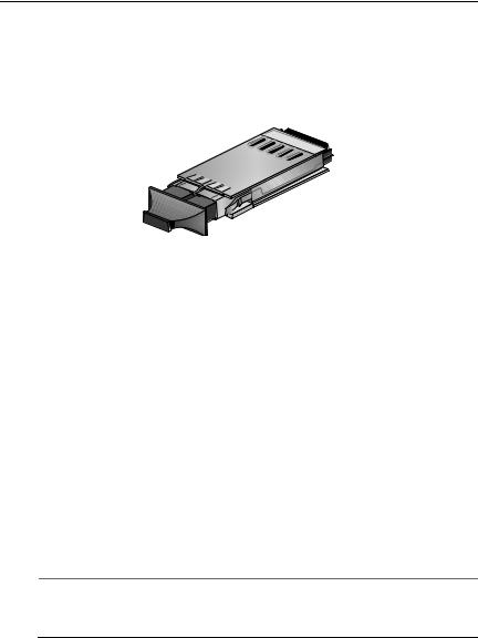
The AT-MC1008/GB converter features one GBIC slot on the front panel. The GBIC slot can accommodate one GBIC transceiver.
The fiber optic GBIC slot on the AT-MC1008/GB converter features one GBIC pluggable transceiver, as shown in Figure 5.
Figure 5. Example of a GBIC Transceiver
When you attach a fiber optic cable to a GBIC transceiver, be sure to observe the following guidelines:
You should verify that you are using the appropriate type of fiber optic cabling. For GBIC cabling specifications, refer to the installation guide provided with the transceiver.
You should verify that the operating specifications of the remote fiber optic port are compatible with the GBIC transceiver. For example, you cannot connect a fiber optic GBIC transceiver with a maximum distance of 40 kilometers and an operating wavelength of 1550 nanometers (nm) to a remote fiber optic port with an maximum distance of only 10 kilometers and an operating wavelength of 1310 nm.
Be sure that the cable connectors is firmly locked into place in the GBIC slot.
Note
For a list of the GBIC transceivers supported can be used with the AT-MC1008/GB converter, contact your ATI sales representative.
19

Chapter 1: Overview
1000Base Fiber Optic SFP Slot on the AT-MC1008/SP Converter
The AT-MC1008/SP converter features one SFP slot on the front panel. The SFP slot can accommodate one SFP transceiver.
The fiber optic SFP slot on the AT-MC1008/SP converter features one SFP pluggable transceiver, as shown in Figure 6.
Figure 6. Example of a SFP Transceiver
When you attach a fiber optic cable to a SFP transceiver, be sure to observe the following guidelines:
You should verify that you are using the appropriate type of fiber optic cabling. For SFP cabling specifications, refer to the installation guide provided with the transceiver.
You should verify that the operating specifications of the remote fiber optic port are compatible with the SFP transceiver. For example, you cannot connect a fiber optic SFP transceiver with a maximum distance of 40 kilometers and an operating wavelength of 1550 nanometers (nm) to a remote fiber optic port with an maximum distance of only 10 kilometers and an operating wavelength of 1310 nm.
Be sure that the cable connectors is firmly locked into place in the SFP slot.
Note
For a list of the SFP transceivers can be used with the AT-MC1008/SP converter, contact your ATI sales representative.
20
AT-MC1008 Series Installation Guide
MODE Push Button
The MODE push button is used to toggle between the three operation modes: Link Test (LT), MissingLink (ML), and Smart MissingLink (SML). This button is located on the front panel. The button cycles through these three modes with each push.
To select between the three modes, use a pointed object such as a pen to depress the push button.
Link Test
The link test is a fast and easy way for you to test the connections between the media converter ports and the end-nodes that are connected to the ports. If a network problem occurs, you can perform a link test to determine which port is experiencing a problem, and so be able to focus your troubleshooting efforts on the cable or end-node where the problem resides.
To perform a link test, toggle the MODE selection button until the LT LED is green. The LINK LEDs for the ports should now be green, indicating that they were able to establish a link with their end-nodes. If a LINK LED is off, the port could not establish a link. Refer to “Troubleshooting” on page 51 for suggestions on how to isolate the problem.
Note
The link test is a normal mode of operation; therefore, performing a link test does not interfere with a media converter’s ability to pass network traffic.
MissingLink
The MissingLink feature enables the two ports on the media converter to pass the “Link” status of their connections to each other. When the media converter detects a loss of connection to an end-node, the media converter shuts down the connection to the other port, thus notifying the end-node that the connection has been lost.
For example, if the twisted pair cable to the 1000Base-T port on the media converter were to fail, the unit would respond by dropping the link on the 1000Base-FX fiber optic port. In this way, the media converter notifies the end-node connected to the fiber optic port that the connection on the twisted pair port has been lost. If the failure had started with the
21

Chapter 1: Overview
fiber optic cabling, the unit would drop the link to the twisted pair port.
The value to this type of network monitoring and fault notification is that some network devices connected directly to the AT-MC1008 media converter can be configured to take a specific action in the event of the loss of connection on a port. In some cases, a network device may be capable of being configured to seek a redundant path to a disconnected end-node or send out a trap to a network management station, and so alert the network administrator of the problem.
Note
MissingLink and Smart MissingLink are disabled when you perform a link test. Consequently, to ensure that MissingLink or Smart MissingLink is enabled on the media converter during normal network operations, always set the MODE push button so that the ML or SML LED is green.
Smart MissingLink
The Smart MissingLink feature performs exactly the same function as MissingLink with one additional feature. When a link is lost on a port, the LINK LED of the port which still has a valid connection to its end-node starts to blink. This allows you to quickly determine which port still has a valid connection (LINK LED blinking) and which port has lost its connection (LINK LED off).
For example, if the network twisted pair cable to the 1000Base-TX port on the converter were to fail, the LINK LED on the 1000Base fiber optic port will blink, indicating a failed connection on the twisted pair port. If the failure had started with the fiber optic cabling, the LINK LED on the twisted pair port would blink.
The value to this type of network monitoring and fault notification is so that you can quickly see which port has failed and troubleshoot your network accordingly.
22

AT-MC1008 Series Installation Guide
LEDs
There are four types of LEDs on the AT-MC1008 Series converters, as shown in Figure 7:
Status LED
Fiber Optic Port LEDs (GBIC or SFP expansion slot)
MODE push button LEDs
Twisted pair port LEDs
Status LED
|
1000Base |
|
1000Base-T |
CLASS 1 |
MODE |
ML |
PWR |
LASER PRODUCT |
|||
LINK |
|
SML |
LINK |
ACT |
|
LT |
ACT |
PORT 1 |
|
|
PORT 2 |
AT-MC1008/GB GIGABIT ETHERNET MEDIA CONVERTER |
|
||
|
MODE Push Button |
|
357 |
|
|
|
|
Fiber Optic Port LEDs |
MODE LEDs |
Twisted Pair Port LEDs |
Figure 7. LEDs on the AT-MC1008 Series Converter
Status LED
The status LED indicates the operating status of the converter. Refer to Figure 7 for the location of this status LED. Each AT-MC1008 Series converter contains only one status LED: PWR; as defined in Table 3.
|
|
Table 3. System Status LEDs |
|
|
|
|
|
LED |
Color |
|
Description |
|
|
|
|
PWR |
Green |
|
Indicates that the unit power is ON. |
|
|
|
|
|
Off |
|
Indicates that the converter power is OFF. |
|
|
|
|
23
Chapter 1: Overview
Twisted pair port LEDs
The twisted pair port LEDs indicate the operating status of the twisted pair port on the AT-MC1008 Series converter. Refer to Figure 7 on page 23 for the location of these LEDs. Each AT-MC1008 Series converter contains two twisted pair port LEDs: LINK and ACT; as defined in Table 4.
|
Table 4. Twisted Pair Port LEDs |
|
|
|
|
LED |
Color |
Description |
|
|
|
LINK |
Green |
Indicates a valid link has been established |
|
|
between the port and the end-node. |
|
|
|
|
Off |
Indicates that there is no link between the port |
|
|
and the end-node. |
|
|
|
ACT |
Blinking |
Indicates that the port is transmitting and/or |
|
Green |
receiving data packets. |
|
|
|
|
Off |
Indicates that there is no activity on the port. |
|
|
|
Fiber Optic Port LEDs (GBIC or SFP Expansion Slot)
The fiber optic port LEDs indicate the operating status of the GBIC module installed in the GBIC expansion on the AT-MC1008/GB model converter, or the SFP transceiver installed in the SFP slot on the AT-MC1008/SP model converter. Refer to Figure 7 on page 23 for the location of these LEDs. Each AT-MC1008 Series converter contains a pair of fiber optic port LEDs: LINK and ACT; as defined in Table 5.
|
|
Table 5. Fiber Optic Port LEDs |
|
|
|
|
|
LED |
Color |
|
Description |
|
|
|
|
LINK |
Green |
|
Indicates a valid link has been established |
|
|
|
between the port and the end-node. |
|
|
|
|
|
Off |
|
Indicates that there is no link between the port |
|
|
|
and the end-node. |
|
|
|
|
ACT |
Blinking |
|
Indicates that the port is transmitting and/or |
|
Green |
|
receiving data packets. |
|
|
|
|
|
Off |
|
Indicates that there is no activity on the port. |
|
|
|
|
24
AT-MC1008 Series Installation Guide
MODE push button LEDs
The MODE push button LEDs indicate the operating status of the three operation modes: Link Test (LT), MissingLink (ML), and Smart MissingLink (SML). Refer to Figure 7 on page 23 for the location of these LEDs. Each AT-MC1008 Series converter contains three MODE push button LEDs: ML, SML, and LT; as defined in Table 6.
Table 6. MODE Push Button LEDs
LED |
Color |
Description |
|
|
|
ML |
Green |
MissingLink mode is enabled. |
|
|
|
|
Off |
MissingLink mode is disabled. |
|
|
|
SML |
Green |
Smart MissingLink mode is enabled. |
|
|
|
|
Off |
Smart MissingLink mode is disabled. |
|
|
|
LT |
Green |
Link Test mode is enabled. |
|
|
|
|
Off |
Link Test mode is disabled. |
|
|
|
25
Chapter 1: Overview
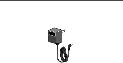
12VDC Power Supply
The 12VDC-version media converters come with the AC/DC power adapter illustrated in Figure 8. This is an approved safety compliant AC power adapter for the 100 and 240V AC versions with an unregulated output of 12VDC.
Figure 8. AC/DC Power Adapter
26

AT-MC1008 Series Installation Guide
Network Topologies
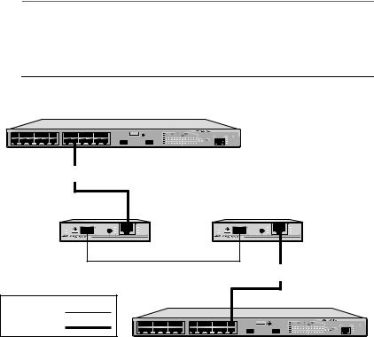
Standalone Topology
A standalone topology uses only one media converter between the endnodes. Figure 9 illustrates a standalone topology that uses two AT-MC1008/SP media converters to interconnect three remote campuses. Campus 1 has an AT-9424T/SP switch which provides a connection of up to 15 kilometers (9.32 miles), are connected to two AT-MC1008/SP media converters via their 1000Base SFP ports. The 1000Base-T twisted pair port on the first media converter is connected to one of the twisted pair ports in the AT-9424T/SP switch at Campus 2; and the 1000Base-T twisted pair port on the second media converter is connected to one of the twisted pair ports in the AT-9424T/SP switch at Campus 3.
Campus 1: AT-9424T/SP
15 km (9.32 mi)
AT-MC1008/SP
SFP |
|
|
1000Base-T |
1000Base |
MODE |
ML |
PWR |
LINK |
|
SML |
LINK |
ACT |
|
LT |
ACT |
PORT 1 |
|
|
PORT 2 |
AT-MC1008/SP GIGABIT ETHERNET MEDIA CONVERTER |
AUTO MDI/MDI-X |
||
|
|
PORT ACTIVITY |
AT-9424T/SP Gigabit Ethernet Switch |
|
|
|
|
TERMINAL |
STATUS |
|
|
|
PORT |
|
SFP |
SFP |
SFP |
|
FAULT |
|
|
MASTER |
||
|
|
|
|
RPS |
|
|
|
|
POWER |
15 km (9.32 mi)
AT-MC1008/SP
SFP |
|
|
1000Base-T |
1000Base |
MODE |
ML |
PWR |
LINK |
|
SML |
LINK |
ACT |
|
LT |
ACT |
PORT 1 |
|
|
PORT 2 |
AT-MC1008/SP GIGABIT ETHERNET MEDIA CONVERTER |
AUTO MDI/MDI-X |
||
100 m (328 ft) maximum |
100 m (328 ft) maximum |
|
AT-9424T/SP |
|
AT-9424T/SP |
Campus 2: AT-9424T/SP |
Campus 3: AT-9424T/SP |
357 |
Multi-mode
Fiber Optic
Twisted Pair
Figure 9. Standalone Topology
27
Chapter 1: Overview
Back-to-Back Topology
In some network configurations you may want to interconnect two media converter in what is referred to as a back-to-back topology. In this topology, the media converter not only extend the distance of your network but also convert the fiber optic cable from twisted pair to fiber optic and back again. Figure 10 illustrates one AT-9424T/SP switch at each campus. The switches are interconnected by two AT-MC1008/SP media converters which provide a connection of up to 15 kilometers (9.32 miles). The 1000Base-T twisted pair ports on the media converters are connected to the twisted pair ports on the switches, while the 1000Base SFP ports on the two AT-MC1008/SP media converters are directly connected to each other.
Note
When using two media converters back-to-back, you must set both converters to the same mode (in example, the first media converter is set to Smart MissingLink mode; then the second converter must also be set to Smart MissingLink mode.)
Campus 1: AT-9424T/SP
|
AT-9424T/SP |
100 m (328 ft) maximum |
|
AT-MC1008/SP |
AT-MC1008/SP |
SFP |
|
|
1000Base-T |
SFP |
|
|
1000Base-T |
1000Base |
MODE |
ML |
PWR |
1000Base |
MODE |
ML |
PWR |
LINK |
|
SML |
LINK |
LINK |
|
SML |
LINK |
ACT |
|
LT |
ACT |
ACT |
|
LT |
ACT |
PORT 1 |
|
|
PORT 2 |
PORT 1 |
|
|
PORT 2 |
AT-MC1008/SP GIGABIT ETHERNET MEDIA CONVERTER |
AUTO MDI/MDI-X |
AT-MC1008/SP GIGABIT ETHERNET MEDIA CONVERTER |
AUTO MDI/MDI-X |
||||
15 km (9.32 mi) |
100 m (328 ft) maximum |
Multi-mode |
|
Fiber Optic |
|
|
AT-9424T/SP |
Twisted Pair |
|
|
376 |
|
Campus 2: AT-9424T/SP |
Figure 10. Back-to-Back Topology
28
Loading...