


 Loading...
AT-x230-10GP
AT-x230-18GP
AT-x230-18GT
AT-x230-28GP
AT-x230-28GT
Gigabit Ethernet Switches
Installation Guide
C613-04068-00 REV D
Copyright 2016 Allied Telesis, Inc.
All rights reserved. No part of this publication may be reproduced without prior written permission from Allied Telesis, Inc.
Allied Telesis and the Allied Telesis logo are trademarks of Allied Telesis, Incorporated. All other product names, company names, logos or other designations mentioned herein are trademarks or registered trademarks of their respective owners.
Allied Telesis, Inc. reserves the right to make changes in specifications and other information contained in this document without prior written notice. The information provided herein is subject to change without notice. In no event shall Allied Telesis, Inc. be liable for any incidental, special, indirect, or consequential damages whatsoever, including but not limited to lost profits, arising out of or related to this manual or the information contained herein, even if Allied Telesis, Inc. has been advised of, known, or should have known, the possibility of such damages.

Electrical Safety and Emissions Standards
This product meets the following standards.
U.S. Federal Communications Commission
Radiated Energy
Note: This equipment has been tested and found to comply with the limits for a Class A digital device pursuant to Part 15 of FCC Rules. These limits are designed to provide reasonable protection against harmful interference when the equipment is operated in a commercial environment. This equipment generates, uses, and can radiate radio frequency energy and, if not installed and used in accordance with this instruction manual, may cause harmful interference to radio communications. Operation of this equipment in a residential area is likely to cause harmful interference in which case the user will be required to correct the interference at his own expense.
Note: Modifications or changes not expressly approved of by the manufacturer or the FCC, can void your right to operate this equipment.
Industry Canada
This Class A digital apparatus meets all requirements of the Canadian Interference-Causing Equipment Regulations. Cet appareil numérique de la classe A respecte toutes les exigences du Règlement sur le matériel brouilleur du Canada.
EMC |
EN 55022 Class A |
|
EN 55024 |
|
EN 61000-3-2 |
|
EN 61000-3-3 |
|
EN 62311 |
|
FCC Part 15 (CFR 47) Class A |
|
VCCI Class A |
|
CISPR 22 Class A |
|
ICES-003 |
Warning: In a domestic environment this product may cause radio interference in which case the user may be required to take adequate measures.
Environmental |
RoHS |
Compliance |
WEEE |
Electrical Safety |
EN 60950-1 (edition 2) |
|
IEC 60950-1 (edition 2) |
|
UL 60950-1 (edition 2) |
Laser Safety |
EN 60825 |
Regulatory |
RCM |
Compliance |
CE |
|
C-UL-US |
|
UL-EU |
i

Translated Safety Statements
Important: The indicates that a translation of the safety statement is available in a PDF document titled Translated Safety Statements posted on the Allied Telesis website at www.alliedtelesis.com.
ii

AT-x230-10GP, AT-x230-18GP, AT-x230-18GT and AT-x230-28GP Switches Installation Guide
Contents
Preface............................................................................................................................................................... |
1 |
Symbol conventions ..................................................................................................................................... |
2 |
Contacting Allied Telesis.............................................................................................................................. |
3 |
Chapter 1: Features........................................................................................................................................... |
6 |
Twisted pair ports .................................................................................................................................. |
6 |
SFP slots ............................................................................................................................................... |
6 |
LEDs...................................................................................................................................................... |
7 |
Installation options................................................................................................................................. |
7 |
Power conservation ............................................................................................................................... |
7 |
MAC address table ................................................................................................................................ |
7 |
Package contents for the AT-x230-10GP Switch......................................................................................... |
8 |
Package contents for AT-x230-18GP and AT-x230-18GT Switches ........................................................... |
9 |
Package contents for the AT-x230-28GP Switch....................................................................................... |
10 |
Package contents for the AT-x230-28GT Switch ....................................................................................... |
11 |
Front and back panels on the AT-x230-10GP Switch ................................................................................ |
12 |
Front and back panels on the AT-x230-18GP Switch ................................................................................ |
14 |
Front and back panels on the AT-x230-18GT Switch ................................................................................ |
16 |
Front and back panels on the AT-x230-28GP Switch ................................................................................ |
18 |
Front and back panels on the AT-x230-28GT Switch ................................................................................ |
20 |
Management software................................................................................................................................ |
22 |
Twisted pair ports....................................................................................................................................... |
23 |
Cable requirements for non-PoE ports ................................................................................................ |
23 |
Power over Ethernet (PoE) ........................................................................................................................ |
25 |
PoE standards ..................................................................................................................................... |
25 |
Powered device classes ...................................................................................................................... |
26 |
Cable requirements ............................................................................................................................. |
26 |
Power budget ...................................................................................................................................... |
27 |
Port prioritization.................................................................................................................................. |
28 |
Wiring implementation ......................................................................................................................... |
29 |
LEDs .......................................................................................................................................................... |
30 |
POWER and FAULT LEDs.................................................................................................................. |
30 |
10/1000BASE-T/100BASE-TX Link/Activity/Speed LED and PoE status LED ................................... |
32 |
10/1000BASE-T/100BASE-TX Link/Activity/Speed LED and Duplex/Collision LED ........................... |
34 |
SFP LEDs............................................................................................................................................ |
36 |
SD card LED........................................................................................................................................ |
37 |
ecofriendly button....................................................................................................................................... |
39 |
Power supply.............................................................................................................................................. |
40 |
Fans ........................................................................................................................................................... |
41 |
Chapter 2: Reviewing safety precautions ........................................................................................................ |
44 |
Selecting a site for the switch..................................................................................................................... |
46 |
Cable specifications ................................................................................................................................... |
47 |
Unpacking the switch: AT-x230-10GP ....................................................................................................... |
48 |
Unpacking the switch: AT-x230-18GP and AT-x230-18GT ....................................................................... |
49 |
Unpacking the switch: AT-x230-28GP ....................................................................................................... |
50 |
Unpacking the switch: AT-x230-28GT ....................................................................................................... |
51 |
Installing the switch on a table or a desktop .............................................................................................. |
52 |
Removing the feet from a switch before installing it in an equipment rack or on a wall ............................. |
53 |
Installing an AT-x230-10GP switch in an equipment rack.......................................................................... |
54 |
Installing an AT-x230-18GP, AT-x230-18GT, or AT-x230-28GT switch in an equipment rack.................. |
56 |
Installing an AT-x230-28GP switch in an equipment rack.......................................................................... |
58 |
iii
Contents |
|
Installing an x230 Series switch on a wall using brackets .......................................................................... |
60 |
Cabling the switch ...................................................................................................................................... |
62 |
Powering on the switch............................................................................................................................... |
64 |
Starting a local management session......................................................................................................... |
66 |
Monitoring the initialization processes........................................................................................................ |
68 |
Installing optional SFP transceivers ........................................................................................................... |
71 |
Chapter 3: Appendix A: Physical specifications ............................................................................................. |
79 |
Dimensions .......................................................................................................................................... |
79 |
Weight.................................................................................................................................................. |
79 |
Environmental specifications ...................................................................................................................... |
80 |
Power specifications................................................................................................................................... |
80 |
Electrical safety and electromagnetic certifications .................................................................................... |
81 |
Connectors and port pinouts ...................................................................................................................... |
82 |
iv

Figures
Figure 1: AT-x230-10GP packaging ...................................................................................................................................... |
8 |
Figure 2: AT-x230-18GP and AT-x230-18GT packaging ...................................................................................................... |
9 |
Figure 3: AT-x230-28GP packaging .................................................................................................................................... |
10 |
Figure 4: AT-x230-28GT packaging .................................................................................................................................... |
11 |
Figure 5: AT-x230-10GP front panel.................................................................................................................................... |
12 |
Figure 6: AT-x230-10GP back panel ................................................................................................................................... |
13 |
Figure 7: AT-x230-18GP front panel.................................................................................................................................... |
14 |
Figure 8: AT-x230-18GP back panel ................................................................................................................................... |
15 |
Figure 9: AT-x230-18GT front panel.................................................................................................................................... |
16 |
Figure 10: AT-x230-18GT back panel ................................................................................................................................. |
17 |
Figure 11: AT-x230-28GP front panel.................................................................................................................................. |
18 |
Figure 12: AT-x230-28GP back panel ................................................................................................................................. |
19 |
Figure 13: AT-x230-28GT front panel.................................................................................................................................. |
20 |
Figure 14: AT-x230-28GT back panel ................................................................................................................................. |
21 |
Figure 15: POWER LED on an x230 Series Switch ............................................................................................................ |
30 |
Figure 16: FAULT LED on an x230 Series Switch............................................................................................................... |
31 |
Figure 17: Link/Activity/Speed and PoE LEDs..................................................................................................................... |
32 |
Figure 18: Link/Activity/Speed and Duplex/Collision LEDs.................................................................................................. |
34 |
Figure 19: SFP Link/Activity LEDs on an x230 Series Switch ............................................................................................. |
36 |
Figure 20: SD card slot LED on an x230 Series Switch ...................................................................................................... |
37 |
Figure 21: ecofriendly button on an x230 Series Switch...................................................................................................... |
39 |
Figure 22: Attaching the rubber feet to a switch .................................................................................................................. |
52 |
Figure 23: Removing the rubber feet from a switch............................................................................................................. |
53 |
Figure 24: Attaching rack mount brackets to an AT-x230-10GP ......................................................................................... |
54 |
Figure 25: Mounting an AT-x230-10GP switch in an equipment rack ................................................................................. |
55 |
Figure 26: Attaching rack mount brackets to the AT-x230-18GP, AT-x230-18GT, or AT-x230-28GT switch ..................... |
56 |
Figure 27: Mounting an AT-x230-18GP, AT-x230-18GT, or |
|
AT-x230-28GT switch in an equipment rack........................................................................................................................ |
57 |
Figure 28: Attaching rack mount brackets to the AT-x230-28GP switch ............................................................................. |
58 |
Figure 29: Mounting an AT-x230-28GP switch in an equipment rack ................................................................................. |
59 |
Figure 30: Attaching wall mount brackets to the side of the switch ..................................................................................... |
60 |
Figure 31: Securing the switch to the wall .......................................................................................................................... |
61 |
Figure 32: Lifting the AC power cable hook on an x230 Series Switch ............................................................................... |
64 |
Figure 33: Plugging in the AC power cord on an x230 Series Switch ................................................................................. |
64 |
Figure 34: Connecting the management cable to the console port of an x230 Series Switch............................................. |
66 |
Figure 35: Switch initialization messages............................................................................................................................ |
68 |
Figure 36: Switch initialization messages (continued) ......................................................................................................... |
69 |
Figure 37: Switch initialization messages (continued) ........................................................................................................ |
70 |
Figure 38: Removing the dust plug from an SFP slot.......................................................................................................... |
71 |
Figure 39: Inserting an SFP transceiver into an SFP slot.................................................................................................... |
72 |
Figure 40: Positioning the SFP handle in the upright position ............................................................................................ |
72 |
Figure 41: Ejecting an SFP transceiver after lowering the SFP handle to the downwards position .................................... |
73 |
Figure 42: RJ45 connector and port pin layout.................................................................................................................... |
82 |
v
vi

Tables
Table 1. |
Twisted pair cable requirements for the non-PoE ports ........................................................................................ |
23 |
Table 2. IEEE powered device classes .............................................................................................................................. |
26 |
|
Table 3. Twisted pair cable requirements for the 10BASE-T and 100BASE-TX ports at 10 or 100Mbps .......................... |
26 |
|
Table 4. Twisted pair cable requirements for the 10/1000BASE-T and 100BASE-TX ports at 1000Mbps ........................ |
27 |
|
Table 5. POWER LED functional descriptions ................................................................................................................... |
30 |
|
Table 6. |
FAULT LED functional descriptions ...................................................................................................................... |
31 |
Table 7. |
Link/Activity/Speed and PoE LED descriptions .................................................................................................... |
33 |
Table 8. |
Link/Activity/Speed and Duplex/Collision LED descriptions ................................................................................. |
35 |
Table 9. |
SFP Link/Activity LED functional descriptions ...................................................................................................... |
37 |
Table 10. |
SD card LED functional descriptions .................................................................................................................. |
38 |
Table 11. Twisted pair cabling and distances .................................................................................................................... |
47 |
|
Table 12. |
Chassis dimensions ............................................................................................................................................ |
79 |
Table 13. |
Chassis weight ................................................................................................................................................... |
79 |
Table 14. |
Environmental specifications .............................................................................................................................. |
80 |
Table 15. |
Input supply voltage ............................................................................................................................................ |
80 |
Table 16. |
Power specifications ........................................................................................................................................... |
80 |
Table 17. |
Safety and electromagnetic emissions certifications ......................................................................................... |
81 |
Table 18. MDI pin signals (10BASE-T or 100BASE-TX) .................................................................................................... |
82 |
|
Table 19. MDIX pin signals (10BASE-T or 100BASE-TX) .................................................................................................. |
82 |
|
Table 20. RJ-45 1000BASE-T connector pinouts ............................................................................................................... |
83 |
|
vii
viii
AT-x230-10GP, AT-x230-18GP and AT-x230-28GP Switches Installation Guide
Preface
This guide contains the installation instructions for the AT-x230-10GP,
AT-x230-18GP, AT-x230-18GT, AT-x230-28GP and AT-x230-28GT
Gigabit Ethernet Switches. This preface contains the following sections:
“Symbol conventions” on page 2
“Contacting Allied Telesis” on page 3
1

Symbol conventions
This document uses the following conventions:
Note
Notes provide additional information.
Caution
Cautions inform you that performing or omitting a specific action may result in equipment damage or loss of data.
Warning
Warnings inform you that performing or omitting a specific action may result in bodily injury.
Warning
Warnings inform you that an eye and skin hazard exists due to the presence of a Class 1 laser device.
2

AT-x230-10GP, AT-x230-18GP and AT-x230-28GP Switches Installation Guide
Contacting Allied Telesis
If you need assistance with this product, you may contact Allied Telesis technical support by going to the Support & Services section of the Allied Telesis web site at www.alliedtelesis.com/support. You can find links for the following services on this page:
24/7 Online Support - Enter our interactive support center to search for answers to your questions in our knowledge database, check support tickets, learn about RMAs, and contact Allied Telesis technical experts.
USA and EMEA phone support - Select the phone number that best fits your location and customer type.
Hardware warranty information - Learn about Allied Telesis warranties and register your product online.
Replacement Services - Submit a Return Merchandise Authorization (RMA) request via our interactive support center.
Documentation - View the most recent installation guides, user guides, software release notes, white papers and data sheets for your product.
Software Updates - Download the latest software releases for your product.
For sales or corporate contact information, go to
www.alliedtelesis.com/purchase and select your region.
3
4

AT-x230-10GP, AT-x230-18GP, AT-x230-18GT and AT-x230-28GP Switches Installation Guide
Chapter 1
Overview
This chapter provides descriptions of the AT-x230-10GP, AT-x230-18GP,
AT-x230-18GT, AT-x230-28GP and AT-x230-28GT Gigabit Ethernet
Switches and contains the following sections:
“Features” on page 6
“Package contents for the AT-x230-10GP Switch” on page 8
“Package contents for AT-x230-18GP and AT-x230-18GT Switches” on page 9
“Package contents for the AT-x230-28GP Switch” on page 10
“Package contents for the AT-x230-28GT Switch” on page 11
“Front and back panels on the AT-x230-10GP Switch” on page 12
“Front and back panels on the AT-x230-18GP Switch” on page 14
“Front and back panels on the AT-x230-18GT Switch” on page 16
“Front and back panels on the AT-x230-28GP Switch” on page 18
“Front and back panels on the AT-x230-28GT Switch” on page 20
“Twisted pair ports” on page 23
“Power over Ethernet (PoE)” on page 25
“LEDs” on page 30
“ecofriendly button” on page 39
“Power supply” on page 40
“Fans” on page 41
5

Chapter 1: Overview
Features
Twisted pair ports
SFP slots
This section describes the hardware features of the x230 Series Gigabit Ethernet Switches.
Here are the basic features of the 10/100/1000Mbps twisted-pair ports:
AT-x230-10GP, AT-x230-18GP, or AT-x230-28GP switches: 8, 16 or 24 PoE ports per switch
AT-x230-18GT or AT-x230-28GT switches: 16 or 24 non-PoE ports per switch
10BASE-T (IEEE 802.3i), 100BASE-TX (IEEE 802.3u) and 1000BASE-T (IEEE 802.3ab) compliant
IEEE 802.3u Auto-Negotiation compliant
Auto-MDI/MDIX
PoE Plus
Full wire-speed non-blocking
IEEE 802.3x Flow Control in 10BASE-T/100BASE-TX full-duplex operation
IEEE 802.3x Back Pressure in 10BASE-T/100BASE-TX halfduplex operation
IEEE803.3z 1000BASE-T Flow Control
Support for jumbo packets up to 10KB
One RJ45 connector on front panel for RS232 console purposes.
Here are the basic features of the SFP ports:
AT-x230-10GP, AT-x230-18GP, and AT-x230-18GT switches: 2 SFP ports per switch
AT-x230-28GP and AT-x230-28GT switches: 4 SFP ports per switch.
Available for 100Mbps or 1000Mbps of fiber, and 1000Mbps of copper
Support 100BASE-FX and 1000BASE-SX/LX transceivers.
You need to purchase SFP transceivers separately. For a list of supported transceivers, contact your Allied Telesis distributor or reseller.
Note
See the product data sheets for the specific ATI SFP modules supported by the x230 Series switches.
6

LEDs
Installation
options
Power conservation
MAC address table
AT-x230-10GP, AT-x230-18GP, AT-x230-18GT and AT-x230-28GP Switches Installation Guide
Here is a brief description of the port LEDs:
POWER and FAULT LEDs; refer to “POWER and FAULT LEDs” on page 30.
Link/Activity/Speed/PoE LEDs for the PoE twisted pair ports; see “10/1000BASE-T/100BASE-TX Link/Activity/Speed LED and PoE status LED” on page 32.
Link/Activity/Speed/Duplex/Collision LEDs for the non-PoE twisted pair ports; see “10/1000BASE-T/100BASE-TX Link/Activity/Speed LED and Duplex/Collision LED” on page 34.
Link/Activity LEDs for the SFP slots; see “SFP LEDs” on page 36.
SD card LED: refer to “SD card LED” on page 37.
Note
The ecofriendly button turns off the LEDs (excluding the POWER LED and SD card LED) to conserve electricity. See “ecofriendly button” on page 39.
The switches can be installed in the following ways:
Rack mounted in a 19-inch equipment rack
Mounted on a desk or tabletop
Wall mounted
The switches implement Eco-Switch Green Power saving features and use less power than the METI specification. The switches have the following power conservation features:
ecofriendly button to turn off the port LEDs when the system is not being monitored
High efficiency power supply
Power scaling based on traffic loads on ports operating at 1000Mbps (port power scaling not available at 10 or 100Mbps)
Power shutdown on unused ports
Here are the basic features of the MAC address table:
Storage capacity up to 16K MAC address entriesAutomatic learning and aging
7

Chapter 1: Overview
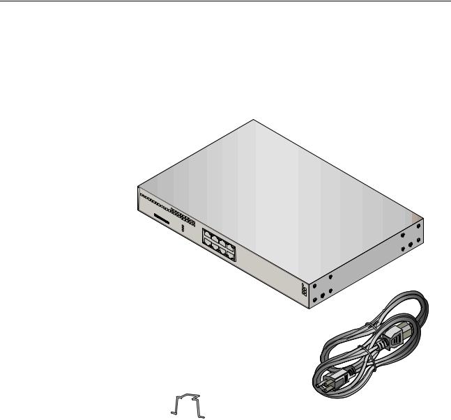
Package contents for the AT-x230-10GP Switch
Figure 1 illustrates the package contents for the AT-x230-10GP Gigabit
Ethernet Switch.
FIGURE 1. AT-X230-10GP PACKAGING
x230- |
|
10 |
|
|
GP |
MA |
|
CA |
|
ddr |
|
ess |
La |
SD |
bel |
C |
|
|
|
ONS |
|
|
|
OLE |
|
|
|
RS- |
|
SD |
|
232 |
FA |
|
|
|
|
ULT |
|
|
|
PO |
WER |
|
1000 |
LINK |
|
|
|
||
|
|
|
ACT |
1 |
|
|
|
|
|
3 |
|
|
|
5 |
|
|
|
|
7 |
2 |
|
|
|
10/100 |
LINK |
|
|
|
|
4 |
|
|
|
ACT |
|
|
|
6 |
|
|
|
PD |
8 |
|
|
|
ON |
SFP

9 


PD |
|
ERR |
|
MAX |
10 |
C |
|
|
URRENT |
AT-x230-10GP
1 Power cable hook |
1 Power cable (1.8m) |
1 Console cable (2m) |
8
AT-x230-10GP, AT-x230-18GP, AT-x230-18GT and AT-x230-28GP Switches Installation Guide
Package contents for AT-x230-18GP and AT-x230-18GT Switches
Figure 2 illustrates the package contents for the AT-x230-18GP and AT- x230-18GT Gigabit Ethernet Switches.
FIGURE 2. AT-X230-18GP AND AT-X230-18GT PACKAGING
AT-x230-18GT
1 Power cable hook |
1 Power cable (1.8m) |
1 Console cable (2m) |
9

Chapter 1: Overview
Package contents for the AT-x230-28GP Switch
Figure 3 illustrates the package contents for the AT-x230-28GP Gigabit
Ethernet Switch.
FIGURE 3. AT-X230-28GP PACKAGING
AT-x230-28GP
1 Power cable (1.8m)
1 Console cable (2m)
2 x Brackets
6 x Screws
1 Power cable hook
10
AT-x230-10GP, AT-x230-18GP, AT-x230-18GT and AT-x230-28GP Switches Installation Guide
Package contents for the AT-x230-28GT Switch
Figure 4 illustrates the package contents for the AT-x230-28GT Gigabit
Ethernet Switch.
FIGURE 4. AT-X230-28GT PACKAGING
AT-x230-28GT
1 Power cable (1.8m)
1 Console cable (2m)
2 x Brackets
6 x Screws
1 Power cable hook
11

Chapter 1: Overview
Front and back panels on the AT-x230-10GP Switch
Figure 5 illustrates the front panel of the AT-x230-10GP Gigabit Ethernet
Switch.
FIGURE 5. AT-X230-10GP FRONT PANEL |
|
|
||||||
PoE status LED |
|
|
SFP slots |
|
||||
|
|
|||||||
Link/activity/speed LED |
|
|
|
|
|
|
||
|
|
|
|
|
|
|||
|
|
|
|
SFP LEDs: |
||||
10/100/1000Mbps PoE+ ports |
|
|
|
|
|
|
||
|
|
|
|
|
|
Upper (left), lower (right) |
||
|
|
|
|
|
|
|
||
x230-10GP |
|
|
1 |
3 |
5 |
7 |
|
SFP |
|
|
|
|
|
|
|
|
|
|
|
|
|
|
|
|
|
9 |
CONSOLE |
|
|
|
|
|
|
|
|
MAC Address Label |
SD |
|
|
|
|
|
|
|
SD |
FAULT |
|
|
|
|
|
|
10 |
POWER |
|
|
|
|
|
|
||
|
|
|
|
|
|
|
|
|
RS-232 |
|
|
2 |
4 |
6 |
8 |
|
|
|
1000 LINK |
ACT |
10/100 LINK |
ACT |
|
PD ON |
PD ERR |
MAX CURRENT |
 SD/Fault/Power LEDs
Console port
 MAC address label
SD card slot
ecofriendly button
12

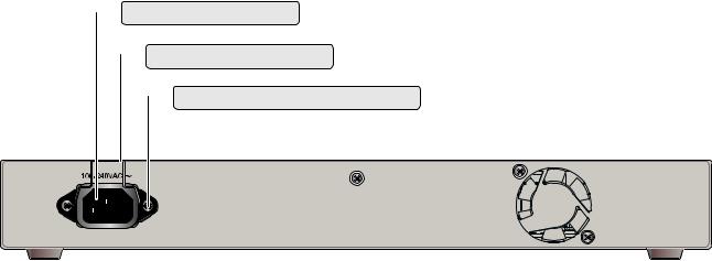
AT-x230-10GP, AT-x230-18GP, AT-x230-18GT and AT-x230-28GP Switches Installation Guide
Figure 6 illustrates the back panel of the AT-x230-10GP Gigabit Ethernet Switch.
FIGURE 6. AT-X230-10GP BACK PANEL
 Power connector
 Power cable hook
 Power cable hook mount
13

Chapter 1: Overview
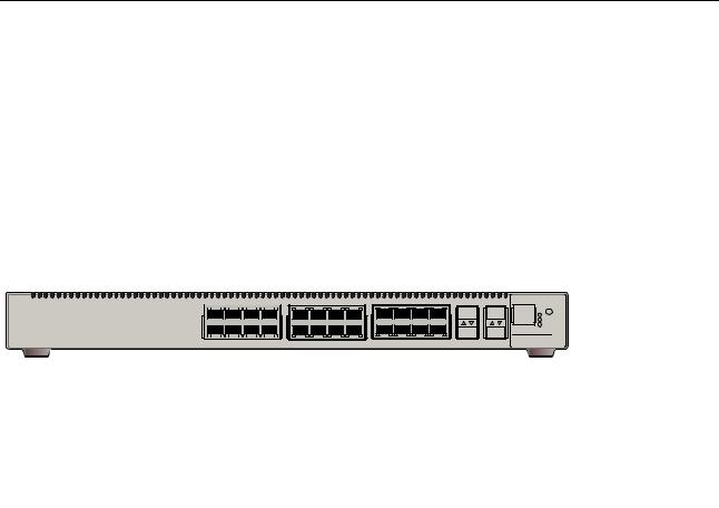
Front and back panels on the AT-x230-18GP Switch
Figure 7 illustrates the front panel of the AT-x230-18GP Gigabit Ethernet
Switch.
FIGURE 7. AT-X230-18GP FRONT PANEL
PoE status LED
Link/activity/speed LED
10/100/1000Mbps PoE+ ports
MAC Address Label |
SD/Fault/Power LEDs |
Console port |
MAC address label |
SD card slot |
ecofriendly button |
SFP slots
SFP LEDs:
Upper (left), lower (right)
14

AT-x230-10GP, AT-x230-18GP, AT-x230-18GT and AT-x230-28GP Switches Installation Guide
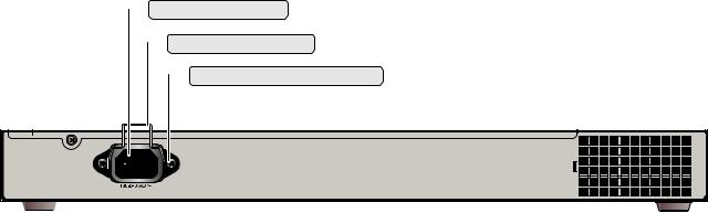
Figure 8 illustrates the back panel of the AT-x230-18GP Gigabit Ethernet Switch.
FIGURE 8. AT-X230-18GP BACK PANEL
Power connector
Power cable hook
Power cable hook mount
15

Chapter 1: Overview
Front and back panels on the AT-x230-18GT Switch
Figure 9 illustrates the front panel of the AT-x230-18GT Gigabit Ethernet
Switch.
FIGURE 9. AT-X230-18GT FRONT PANEL
Duplex Mode LED
Link/activity/speed LED
10/100/1000 Mbps ports
SFP slots
SFP LEDs:
Upper (left), lower (right)
MAC Address Label |
SD/Fault/Power LEDs |
Console port |
MAC address label |
SD card slot |
ecofriendly button |
16
AT-x230-10GP, AT-x230-18GP, AT-x230-18GT and AT-x230-28GP Switches Installation Guide
Figure 10 illustrates the back panel of the AT-x230-18GT Gigabit Ethernet Switch.
FIGURE 10. AT-X230-18GT BACK PANEL
 Power connector
 Power cable hook
 Power cable hook mount
17
Chapter 1: Overview
Front and back panels on the AT-x230-28GP Switch
Figure 11 illustrates the front panel of the AT-x230-28GP Gigabit Ethernet
Switch.
FIGURE 11. AT-X230-28GP FRONT PANEL
PoE status LED
Link/activity/speed LED
10/100/1000Mbps PoE+ ports |
SFP slots
SFP LEDs:
Upper (left), lower (right)
ecofriendly button |
SD/Fault/Power LEDs |
Console port |
 SD card slot
18
AT-x230-10GP, AT-x230-18GP, AT-x230-18GT and AT-x230-28GP Switches Installation Guide
Figure 12 illustrates the back panel of the AT-x230-28GP Gigabit Ethernet Switch.
FIGURE 12. AT-X230-28GP BACK PANEL
 Power connector
 Power cable hook
 Power cable hook mount
19
Loading...