


 Loading...
RAPIER SWITCH
USER GUIDE
Software Release 2.5.1
2 |
Rapier Switch User Guide |
Rapier Switch User Guide
Document Number C613-02025-00 Rev B.
Copyright © 2002 Allied Telesyn International Corp.
19800 North Creek Parkway, Suite 200, Bothell, WA 98011, USA.
All rights reserved. No part of this publication may be reproduced without prior written permission from Allied Telesyn.
Allied Telesyn International, Corp. reserves the right to make changes in specifications and other information contained in this document without prior written notice. The information provided herein is subject to change without notice. In no event shall Allied Telesyn be liable for any incidental, special, indirect, or consequential damages whatsoever, including but not limited to lost profits, arising out of or related to this manual or the information contained herein, even if Allied Telesyn has been advised of, known, or should have known, the possibility of such damages.
All trademarks are the property of their respective owners.
Software Release 2.5.1
C613-02025-00 Rev B

3
Contents
CHAPTER 1 |
Introduction |
|
|
Why Read This User Guide? .............................................................................. |
5 |
|
Where To Find More Information ...................................................................... |
6 |
|
Technical support .............................................................................................. |
6 |
|
What Can the Rapier Switch Do? ...................................................................... |
7 |
|
Switching Features ..................................................................................... |
7 |
|
Routing Features ........................................................................................ |
8 |
|
Special Features Licences ............................................................................ |
9 |
CHAPTER 2 |
Getting Started |
|
|
Simple Switching ............................................................................................ |
11 |
|
Command Line Interface ................................................................................. |
11 |
|
Logging In ................................................................................................ |
12 |
|
Giving the Switch an IP Address ............................................................... |
12 |
|
Entering Commands ................................................................................. |
13 |
|
The Graphical User Interface (GUI) .................................................................. |
13 |
|
Enabling and Disabling the GUI ................................................................ |
13 |
|
Accessing the GUI .................................................................................... |
14 |
|
Enabling Special Feature Licences .................................................................... |
15 |
CHAPTER 3 Operating the Switch |
|
|
|
User Privileges ................................................................................................. |
17 |
|
File Subsystem ................................................................................................ |
17 |
|
Online CLI Help ............................................................................................... |
18 |
|
Configuration Scripts ...................................................................................... |
19 |
|
Saving Configuration Entered with the GUI .............................................. |
20 |
|
Saving Configuration Entered with the CLI ............................................... |
20 |
|
Editor ............................................................................................................. |
20 |
|
Install Information ........................................................................................... |
21 |
|
Releases and Patches into the Switch .............................................................. |
23 |
|
Example: Install Software Upgrade for Rapier Switch ................................ |
25 |
|
SNMP and MIBs .............................................................................................. |
26 |
CHAPTER 4 Layer 2 Switching |
|
|
|
Switch Ports .................................................................................................... |
29 |
|
Enabling and Disabling Switch Ports ......................................................... |
29 |
|
Autonegotiation of Port Speed and Duplex Mode ..................................... |
32 |
|
Port Trunking ........................................................................................... |
33 |
|
Packet Storm Protection ........................................................................... |
34 |
|
Port Mirroring .......................................................................................... |
36 |
|
Port security ............................................................................................. |
37 |
|
Virtual Local Area Networks (VLANs) ............................................................... |
38 |
|
VLAN Tagging .......................................................................................... |
39 |
Software Release 2.5.1
C613-02025-00 REV B
4 |
Rapier Switch Software Reference |
|
|
VLAN Membership of Untagged Packets .................................................. |
42 |
|
Creating VLANs ........................................................................................ |
43 |
|
Summary of VLAN tagging rules ............................................................... |
44 |
|
Protected VLANs ...................................................................................... |
45 |
|
VLAN Interaction with STPs and Trunk Groups .......................................... |
45 |
|
Generic VLAN Registration Protocol (GVRP) ..................................................... |
45 |
|
Layer 2 Switching Process ............................................................................... |
46 |
|
The Ingress Rules ...................................................................................... |
46 |
|
The Learning Process ................................................................................ |
47 |
|
The Forwarding Process ............................................................................ |
48 |
|
Layer 2 Filtering ........................................................................................ |
49 |
|
The Egress Rules ....................................................................................... |
50 |
|
Quality of Service ............................................................................................ |
50 |
|
Spanning Tree Protocol (STP) ........................................................................... |
52 |
|
Spanning Tree Modes ............................................................................... |
53 |
|
Spanning Tree and Rapid Spanning Tree Port States .................................. |
53 |
|
Overlapping VLANs belonging to multiple Spanning Tree instances ........... |
54 |
|
Configuring STP ....................................................................................... |
55 |
|
Interfaces to Layer 3 Protocols ......................................................................... |
64 |
|
IGMP Snooping .............................................................................................. |
64 |
|
Triggers ........................................................................................................... |
67 |
|
CHAPTER 5 Layer 3 Switching |
|
|
Internet Protocol (IP) ....................................................................................... |
69 |
|
IP Multicasting ................................................................................................ |
70 |
|
Routing Information Protocol (RIP) .................................................................. |
70 |
|
Novell IPX ....................................................................................................... |
71 |
|
AppleTalk ........................................................................................................ |
72 |
|
Resource Reservation Protocol (RSVP) .............................................................. |
72 |
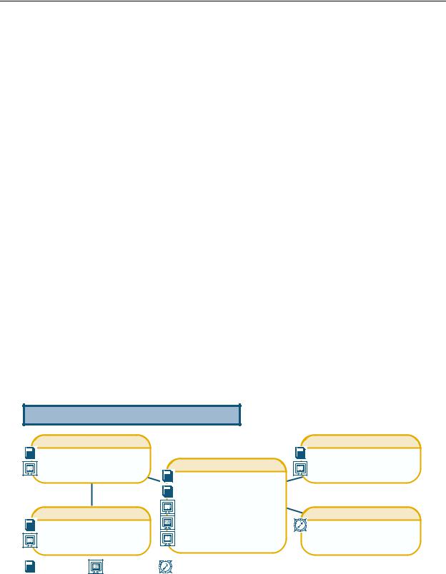
Documentation Roadmap
Network Service Modules |
|
Uplink Module |
||
NSM Quick Install Guide |
|
Uplink Module Quick Install Guide |
||
NSM Hardware Reference |
Rapier Switch |
Uplink Module Hardware Reference |
||
|
||||
|
|
Safety and Statutory Information |
|
|
|
|
Switch Quick Install Guide |
|
|
Port Interface Cards |
Switch Hardware Reference |
General Customer Support |
||
Switch Software Reference |
||||
PIC Quick Install Guide |
Visit www.alliedtelesyn.co.nz for |
|||
Rapier Switch User Guide |
||||
PIC Hardware Reference |
the latest documentation, FAQ, |
|||
|
and support information |
|||
|
|
|
||
Printed |
Acrobat PDF |
Website |
|
|
Software Release 2.5.1
C613-02025-00 REV B

Introduction |
5 |
Chapter 1
Introduction
Welcome to the Rapier Series Layer 3 Gigabit switch, combining wire speed Layer 2 and Layer 3 IP switching, with a powerful multiprotocol routing software suite.
Why Read This User Guide?
This User Guide describes how to get started accessing the switch’s Command Line Interface (CLI) and its Graphical User Interface (GUI), and how to configure the Layer 2 switching features. For more detailed descriptions of all commands and display outputs see the Rapier Switch Software Reference. The user guide is organised into the following chapters:
■Chapter 1, Introduction introduces the Rapier switch and gives an overview of the features of the Rapier switch and its documentation.
■Chapter 2, Getting Started describes how to gain access to the switch’s command line and graphical user interfaces.
■Chapter 3, Operating the Switch introduces general operation, management and support features, including user authentication, loading and installing support files, and SNMP MIBs.
■Chapter 4, Layer 2 Switching describes how to configure Layer 2 switching features, including switch ports, VLANs and STP.
■Chapter 5, Layer 3 Switching describes how to use Layer 3 switching over VLANs, including IP, Novell IPX and AppleTalk. Full descriptions of the switch’s support for these protocols are found in the Rapier Switch Software Reference.
Software Release 2.5.1
C613-02025-00 REV B

6 |
Rapier Switch Software Reference |
Where To Find More Information
Before installing the switch and any expansion options, read the important safety information in the Safety and Statutory Information booklet. Follow the Quick Install Guides step-by-step instructions for physically installing the switch and its expansion options. The Hardware References give detailed information about the equipment hardware. Once you are familiar with the basic operations of the switch, use the Software Reference for full command syntax descriptions and for full descriptions of the switch’s routing features.
The latest versions of user documentation for the Rapier family of switches can be downloaded from the on-line support site at http://www.alliedtelesyn.co.nz/support/rapier. The documentation set for the Rapier switch includes:
■Rapier Switch Safety and Statutory Information
■Rapier Switch Quick Install Guide
■Rapier Switch Documentation and Tools CD-ROM, which includes the following PDF documents:
•Rapier Switch Safety and Statutory Information
•Rapier Switch Quick Install Guide,
•Rapier Switch Hardware Reference
•Rapier Switch Software Reference
•Rapier Uplink Module Quick Install Guide
•Rapier Uplink Module Hardware Reference
•Network Service Module Quick Install Guide
•Network Service Module Hardware Reference
•Port Interface Card Quick Install Guide
•Port Interface Card Hardware Reference
Technical support
For on-line support for your Rapier switch, see our on-line support page at http://www.alliedtelesyn.co.nz/support/rapier. If you require further assistance, contact your authorised Allied Telesyn distributor or reseller.
This page will also contain the latest release of the switch software. The LOAD command can be used to download software upgrades directly from the Allied Telesyn Research web site to the switch’s FLASH memory. Use the SET INSTALL command to enable the new software release (“Example: Install Software Upgrade for Rapier Switch” on page 25).
Software Release 2.5.1
C613-02025-00 REV B

Introduction |
7 |
What Can the Rapier Switch Do?
The Rapier switch software support for the Rapier Series switches and their expansion options provides wirespeed Layer 2 switching, including support for Virtual LANs, wirespeed Layer 3 IP switching, and Layer 3 multiprotocol routing.
Switching Features
The main Layer 2 features of the switch are:
■High performance, non-blocking, wire-speed Layer 2 switching (“Layer 2 Switching Process” on page 46).
■Packet Forwarding at wire speed (“The Forwarding Process” on page 48).
■Store and Forward switching mode.
■Autonegotiation of link speed and duplex mode for 10/100 Mbps speed on all 100BASE TX ports (“Autonegotiation of Port Speed and Duplex Mode” on page 32).
■Autonegotiation of duplex mode for 10/100 and gigabit Ethernet ports (“Autonegotiation of Port Speed and Duplex Mode” on page 32).
■Automatic, configurable MAC address learning and ageing, supporting up to 8191 MAC addresses per switch (“The Learning Process” on page 47).
■Switch Filtering (“Layer 2 Filtering” on page 49).
■Layer 3 Filtering (Switching chapter in Rapier Switch Software Reference).
■Broadcast Storm Protection (“Packet Storm Protection” on page 34).
■Virtual LANs defined by port membership (“Virtual Local Area Networks (VLANs)” on page 38).
■Spanning Tree Protocol (“Spanning Tree Protocol (STP)” on page 52).
■Priority tagging to support four QOS egress queues (“Quality of Service” on page 50).
■Port trunking to spread traffic over several links (“Port Trunking” on page 33).
■Port mirroring (“Port Mirroring” on page 36).
■IGMP (Internet Group Management Protocol) snooping (“IGMP Snooping” on page 64).
Software Release 2.5.1
C613-02025-00 REV B

8 |
Rapier Switch Software Reference |
Routing Features
In addition to Layer 2 and Layer 3 switching, the Rapier switch provides a wide array of multiprotocol routing, security and network management features.
IP routing is performed at wire-speed. Other Layer 3 routing is performed by the CPU, and increasing the routing load on the CPU decreases its performance.
Some features require the addition of WAN interfaces via Network Service Modules (NSMs) and Port Interface Cards (PICs) installed in the NSM bay on the rear of the switch.
Features provided by the routing software suite include:
■IP version 4 routing
■IP version 4 multicasting
■IP version 6 routing
■Network Address Translation (NAT) (not between switch ports)
■Dynamic IP Address Assignment
■IP Dynamic Filtering Firewall
■IP Multihoming
■IP RIP and IP RIPv2
■DNS Relay
■Demand IP
■IP Filtering (not between switch ports)
■IP Packet Prioritisation (not between switch ports)
■Generic Routing Encapsulation (GRE)
■Basic Rate and Primary Rate access to Integrated Services Digital Network (ISDN) services, with dial-on-demand and channel aggregation.
■Time Division Multiplexing (TDM) over G.703 links
■Frame Relay
■X.25
■ARP, Proxy ARP and Inverse ARP address resolution protocols.
■BACP (Bandwidth Allocation Control Protocol)
■PPP Multilink
■PPP over Ethernet (PPPoE)
■Bandwidth on Demand
■CLI, PAP and CHAP
■Virtual Router Redundancy Protocol (VRRP) for fault tolerant internet gateways (on NSM ports only)
■IPsec
■ISAKMP Key Management
■Data Compression
■Predictor Data Compression
Software Release 2.5.1
C613-02025-00 REV B
Introduction |
9 |
■STAC Data Compression
■L2TP
■Telnet client and server.
■A sophisticated and configurable event logging facility for monitoring and alarm notification to single or multiple management centres.
■Triggers for automatic and timed execution of commands in response to events.
■Scripting for automated configuration and centralised management of configurations.
■Dynamic Host Configuration Protocol (DHCP) for automatically assigning IP addresses and other configuration information to PCs and other hosts on TCP/IP networks.
■Group management support for IP multicasting: IGMP version 2.
■Support for the Simple Network Management Protocol (SNMP), standard MIBs and the Allied Telesyn Enterprise MIB, enabling the switch to be managed by a separate SNMP management station.
■An HTTP client that allows files to be downloaded directly from a web server to the switch’s FLASH memory, and an HTTP server that serves web pages from FLASH.
For a complete description of the switch’s routing software, see the Rapier
Switch Software Reference.
Special Features Licences
You need a special feature licence and password to activate some special features over and above the standard software release. Typically, these special features are covered by government security regulations. Special feature licences and passwords are quite separate and distinct from the standard software release licences and passwords. Some of the software features that require a special features licence are:
■Triple DES S/W
■Firewall SW
■Firewall SMTP Application Gateway
■Firewall HTTP Application Gateway
■DES encryption
■IPv6
■BGP-4
■IP Multicast routing: DVMRP and PIM-Sparse Mode
■IPX routing
■Demand IPX
■IPX/SPX Spoofing
■IPX Filtering (not between switch ports)
■AppleTalk
■Resource Reservation Protocol (RSVP)
■Load balancer
Software Release 2.5.1
C613-02025-00 REV B
10 |
Rapier Switch Software Reference |
Most software features that require a special feature licence are bundled into one of three special feature licence packs:
■Full Layer 3 Feature Licence
■Advanced Layer 3 Feature Licence
■Security Pack Feature Licence
For more information contact your Allied Telesyn authorised distributor or reseller.
For information on how to enable special feature licences see “Enabling Special
Feature Licences” on page 15.
Software Release 2.5.1
C613-02025-00 REV B
Getting Started |
11 |
Chapter 2
Getting Started
The Rapier switch is supplied with default settings which allow it to operate immediately as a switch, without any configuration. Even if this is all you want to use the switch for, you should still gain access to the switch configuration, if only to change the manager password to prevent unauthorised access.
To take advantage of the full range of advanced Layer 2 switching features, the switch configuration must be changed. Layer 3 routing capabilities may also require detailed configuration. The switch has both a Command Line Interface (CLI) and a Graphical User Interface (GUI) for configuration and management. Before you can use the GUI, you will need to login to the switch and use its CLI to allocate an IP address.
Simple Switching
If all you want the switch to do is switch traffic on your LAN, you need not perform any configuration. Simply power up the switch and connect devices to the switch ports. Switch learning is enabled by default, and all valid packets will be forwarded (“Layer 2 Switching Process” on page 46).
Command Line Interface
To use the command line interface (CLI) for configuring the switch, the first thing you need to do after physically installing the switch is to start a terminal session to access the switch (see Table 1 and the Rapier Switch Quick Install Guide).
To start a terminal session, do one of the following:
■Connect a VT100-compatible terminal to the RS-232 Terminal Port, set the communications parameters on the terminal (Table 1 on page 12), and press [Enter] a few times until the switch’s login prompt appears; or
■Connect to the COM port of a PC running terminal emulation software such as Windows Terminal or HyperTerminal to the RS-232 Terminal Port, set the communications parameters on the terminal emulation software (Table 1 on page 12), and press [Enter] a few times until the switch’s login prompt appears.
Software Release 2.5.1
C613-02025-00 REV B
12 |
|
Rapier Switch Software Reference |
|
Table 1: Parameters for terminal communication . |
|
|
|
|
|
Parameter |
Value |
|
|
|
|
Baud rate |
9600 |
|
|
|
|
Data bits |
8 |
|
|
|
|
Parity |
None |
|
|
|
|
Stop bits |
1 |
|
|
|
|
Flow control |
Hardware |
|
|
|
Logging In
A user accessing the switch from a terminal or PC connected to the front panel RS-232 terminal port (asyn0), or via a Telnet connection, must enter a login name and password to gain access to the command prompt. When the switch is supplied, it has a manager account with an initial password friend. Enter your login name at the login prompt:
Enter your login name at the login prompt:
login: manager
Enter the password at the password prompt:
password: friend
This password should be changed to prevent unauthorised access to the switch, using the command:
SET PASSWORD
Make sure you remember the new password you create, as a lost password cannot be retrieved, and would mean losing access for configuring and monitoring the switch.
Giving the Switch an IP Address
Once you have logged into the manager account you will be able to enter commands from this document and from the Rapier Switch Software Reference.
Enable IP, then add an IP interface over the default VLAN (vlan1) and assign it an IP address (e.g. 192.168.1.1), using the commands:
ENABLE IP
ADD IP INTERFACE=vlan1 IPADDRESS=192.168.1.1
Once the switch is configured with an IP address, the command line interface can also be accessed by using Telnet to the switch from an IP host.
Software Release 2.5.1
C613-02025-00 REV B

Getting Started |
13 |
Entering Commands
The switch is controlled with commands described in this document and in the Rapier Switch Software Reference. While the keywords in commands are not case sensitive, the values entered for some parameters are. The switch supports command line editing and recall (Table 2 on page 13).
Table 2: Command line editing functions and keystrokes
Function |
VT100-compatible Keystroke |
|
|
Move cursor within command line |
←, → |
|
|
Delete character to left of cursor |
[Delete] or [Backspace] |
|
|
Toggle between insert/overstrike |
[Ctrl/O] |
|
|
Clear command line |
[Ctrl/U] |
|
|
Recall previous command |
↑ or [Ctrl/B] |
|
|
Recall next command |
↓ or [Ctrl/F] |
|
|
Display command history |
[Ctrl/C] or |
|
SHOW ASYN HISTORY |
|
|
Clear command history |
RESET ASYN HISTORY |
|
|
Recall matching command |
[Tab] or [Ctrl/I] |
|
|
The Graphical User Interface (GUI)
The switch may be configured and managed with an HTTP-based Graphical User Interface (GUI). The GUI may be accessed with Internet Explorer version 5 or greater. A copy of Internet Explorer can be found on the switch’s Documentation and Tools CD-ROM. JavaScript must be enabled.
Use the menus and buttons on the GUI pages to navigate, not your browser’s buttons, to ensure that the configuration settings are saved correctly.
Enabling and Disabling the GUI
The GUI is enabled by default. To enable or disable the GUI, use the following commands:
ENABLE GUI
DISABLE GUI
When enabled, the GUI will only work if a valid resource file for the hardware model is present in FLASH memory, and if the HTTP server is enabled (see the
Operations chapter of the Rapier Switch Software Reference).
Software Release 2.5.1
C613-02025-00 REV B

14 |
Rapier Switch Software Reference |
Accessing the GUI
To allow the GUI to be browsed to, the switch’s VLAN1 interface must be given an IP address. In some situations, routing information must also be configured. For more information about IP configuration, see the Internet Protocol (IP) chapter of the Rapier Switch Software Reference).
You can optionally browse to the GUI with a Secure Sockets Layer (SSL) connection. This means that sensitive data including passwords and email addresses can not be accessed by malicious parties. For details on configuring a SSL connection for the GUI, refer to the Secure Sockets Layer (SSL) chapter of the
Rapier Switch Software Reference).
To access the GUI:
1. Access the switch’s command line interface.
See the switch’s Quick Install Guide for more information.
2.Enable IP, using the command:
ENABLE IP
3.Assign the VLAN1 interface an IP address in the required subnet, using the command:
SET IP INTERFACE=vlan1 IP=ipaddress MASK=mask
4. If the PC from which you will access the GUI is on a different subnet to the switch, add a route from the PC to the switch, using the command:
ADD IP ROUTE=PC-ipaddress INTERFACE=vlan1
NEXTHOP=switch-ipaddress
5.If you access the Internet through a proxy server, set your browser to bypass the proxy for the VLAN1 interface’s IP address.
6.Point your web browser at VLAN1’s IP address.
7.At the login prompt, enter the user name and password.
User Name: manager
Password: friend
The home page is displayed. Select options to configure and manage the switch.
To change the password, select Management > Users from the sidebar menu.
Select the Manager account and click Modify.
Getting help
To access the GUI’s context-sensitive help system, click on the Help button in the sidebar menu.
Software Release 2.5.1
C613-02025-00 REV B

Getting Started |
15 |
Enabling Special Feature Licences
You must enable the special feature licence you have purchased before you can use the licenced features. You will need the password provided by your authorised distributor or reseller. The advanced upgrade licence and password are different from the standard software release licence and password. The licence cannot be transferred from one router to another.
For software features that require a special feature licence see “Special Features
Licences” on page 9.
You must order passwords for special feature licences from your authorised distributor or reseller. You must specify the special feature licence bundle and the serial number(s) of the switch(s) on which the special feature licences are to be enabled.
The password for a special feature licence is a string of at least 16 hexadecimal characters, and encodes the special feature or features covered by the license, and the switch serial number. The password information is stored in the switch’s FLASH memory.
To enable or disable the AT-RPFL3Upgrade use the commands:
ENABLE FEATURE=AT-RPFL3Upgrade PASSWORD=password
DISABLE FEATURE=AT-RPFL3Upgrade
Other features on the switch, such as Firewall, Remote Secure Shell and Triple DES encryption, and support for Public Key Infrastructure may also need special feature licences. To list the current special feature licences use the command:
SHOW FEATURE[={featurename|index}]
Software Release 2.5.1
C613-02025-00 REV B

Operating the Switch |
17 |
Chapter 3
Operating the Switch
This chapter introduces general operation, management and support features, including user authentication, loading and installing support files, and SNMP MIBs. For more information see Chapter 1, Operation in the Rapier Switch Software Reference.
User Privileges
The command processor supports three levels of privilege, USER, MANAGER, and SECURITY OFFICER, distinguished by the prompt displayed by the command processor when it is ready to receive commands. A USER level prompt looks like:
>
while a MANAGER prompt looks like:
Manager >
and a SECURITY OFFICER prompt looks like:
SecOff >
See Chapter 1, Operation in the Rapier Switch Software Reference for more information about creating new accounts with user, manager and security officer privileges.
File Subsystem
FLASH memory is structured like a file subsystem. Files can be saved, renamed, listed and deleted. Release files, online help files, configuration scripts and other scripts are all stored as files in FLASH memory.
File names of up to 16 characters long, with extensions of 3 characters (DOS 16.3 format), are supported on the switch. However, files on the switch are stored in FLASH and NVS using the DOS 8.3 format of 8 characters long, with extensions of 3 characters. For example, the file extralongfilenam.cfg may be saved as extral~1.cfg in the FLASH File System. Therefore, files can be accessed via two file names, either of which can be used for file management.
A translation table, named longname.lfn, converts file names between DOS 16.3 format and DOS 8.3 format. To reconcile file names the switch consults the
Software Release 2.5.1
C613-02025-00 REV B
18 |
Rapier Switch Software Reference |
translation table which is synchronised with file contents in memory. For more information about working with files see the Working With Files section,
Operation chapter, AR400 Series Router Software Reference.
To display the files in FLASH, use the command:
SHOW FILE
Table 3: Example output from the SHOW FILE command.
Filename Device Size Created Locks
----------------------------------------------------------------------------
28-72.pat |
flash |
111764 |
05-May-1997 12:41:42 |
0 |
|
28-74ang.rel |
flash |
2013756 |
09-May-1997 15:58:55 |
0 |
|
28f72-06.pat |
flash |
123268 |
18-Apr-1997 15:58:16 |
0 |
|
release.lic |
flash |
32 |
08-May-1997 |
16:43:49 |
0 |
test.cfg |
flash |
1698 |
09-May-1997 |
10:39:42 |
0 |
config.ins |
nvs |
32 |
09-May-1997 |
10:22:46 |
0 |
sixteenalongfile.scp |
flash |
24 |
30-May-1997 |
15:10:12 |
0 |
----------------------------------------------------------------------------
The Locks field indicates the number of concurrent processes using the file.
The switch automatically compacts FLASH memory when a maximum threshold of deleted files is reached. Compaction frees space for new files by discarding garbage. A message will appear when FLASH compaction has been activated. Another message appears when FLASH compaction is complete.
While FLASH is compacting, do not restart the switch or use any commands that affect the FLASH file subsystem. Do not restart the switch, or create, edit, load, rename or delete any files until a message confirms that FLASH file compaction is completed. Interrupting flash compaction may result in damage to files.
Online CLI Help
Online help is available for all switch commands in the CLI. Typing a question mark “?” at the end of a partially completed command displays a list of the parameters that may follow the current command line, with the minimum abbreviations in uppercase letters. The current command line is then redisplayed, ready for further input.
An online help facility provides more detailed help information via the command:
HELP [topic]
If a topic is not specified, a list of available topics is displayed. The HELP command displays information from the system help file stored in FLASH memory. The help file used by the HELP command must be defined using the command:
SET HELP=helpfile
Software Release 2.5.1
C613-02025-00 REV B

Operating the Switch |
19 |
The current help file and other system information can be displayed with the command:
SHOW SYSTEM
Table 4: Example of output from the SHOW SYSTEM command
Switch System Status |
|
Time 14:29:17 Date 12-Sep-2000. |
||||
Board |
ID |
Bay Board Name |
|
Rev |
Serial number |
|
-------------------------------------------------------------------------- |
||||||
Base |
86 |
|
AT-RP24 Rapier 24 |
P2-1 |
49867449 |
|
-------------------------------------------------------------------------- |
||||||
Memory - |
DRAM |
: |
32768 kB |
FLASH : 6144 kB |
|
|
-------------------------------------------------------------------------- |
||||||
SysDescription |
|
|
|
|
|
|
CentreCOM AT-RP24 |
Rapier 24 version 2.1.0-00 04-Sep-2000 |
|
||||
SysContact |
|
|
|
|
|
|
SysLocation |
|
|
|
|
|
|
SysName |
|
|
|
|
|
|
SysUpTime |
|
|
|
|
|
|
30262 ( 00:05:02 ) |
|
|
|
|
||
Software Version: 2.1.0-00 04-Sep-2000 |
|
|
||||
Release Version |
: 2.1.0-00 04-Sep-2000 |
|
|
|||
Release built |
: Sep 12 2000 at 14:28:59 |
|
|
|||
Patch Installed |
: NONE |
|
|
|
||
Territory |
|
: usa |
|
|
|
|
Help File |
|
: help.hlp |
|
|
|
|
Main PSU |
|
: On |
Main Fan |
: On |
|
|
RPS Monitor |
|
: On |
RPS Connected |
: Yes |
|
|
RPS PSU |
|
: On |
|
|
|
|
Boot configuration file: vts.cfg (exists) |
|
|
||||
Current configuration: vts.cfg |
|
|
|
|||
Security Mode |
: Disabled |
|
|
|
||
Warning (248283): No patches found.
Configuration Scripts
At boot the switch executes the commands in the boot script to configure the switch. A boot script is a sequence of standard commands that the switch executes at start-up. The default boot script is called boot.cfg, but an alternative script file can be defined as the boot script using the command:
SET CONFIG=filename
A configuration file is a script made up of the same commands as are used in the CLI. It can be edited manually using the switch’s built in editor (“Editor” on page 20), or uploaded to a PC and edited using any text editor using the UPLOAD command (Chapter 1, Operation in the Rapier Switch Software Reference).
Software Release 2.5.1
C613-02025-00 REV B
20 |
Rapier Switch Software Reference |
Saving Configuration Entered with the GUI
Configuration changes applied using the GUI can be saved to a configuration script by clicking the Save button on any GUI page that has one. A pop-up Save window gives the option of saving to the boot configuration file, the current configuration file, another existing file or a new file.
Saving Configuration Entered with the CLI
Subsequent commands entered from the command line or executed from a script affect only the dynamic configuration in memory, which is not retained over a power cycle. Changes are not automatically stored in nonvolatile memory. When the switch is restarted the configuration will be restored to that defined by the boot script, or if the switch was restarted using the RESTART command, any script specified in the RESTART command.
To retain any configuration changes made after boot across a restart or power cycle, save the modified configuration as a script file, using the command:
CREATE CONFIG=filename
The configuration file created by the GUI or the CREATE CONFIG command records passwords in encrypted form, not in cleartext.
Editor
The switch has a built-in full-screen text editor for editing script files stored on the switch file subsystem. Scripts can be run manually, or run when a trigger automatically activates on some specified events in the switch. See “Triggers” on page 67, and the Trigger Facility chapter in the Rapier Switch Software Reference. To access the editor, use the command:
EDIT [filename]
The file name is optional as a file can be loaded, or a new file can be created from within the editor itself (Figure 1 on page 21).
Software Release 2.5.1
C613-02025-00 REV B
Operating the Switch |
21 |
Figure 1: The editor screen layout.
The editor uses VT100 command sequences and should only be used with a
VT100-compatible terminal, terminal emulation program or Telnet client.
To display editor Help at any time while in the editor press [Ctrl/K,H]; that is, hold down the Ctrl key and press in turn the K key then the H key.
Install Information
The INSTALL module is responsible for maintaining install information and loading the correct install at boot. A release is a binary file containing the code executed by the switches CPU. There may also be a patch file, and additional binary file that modifies the original release file. An install is a record identifying a release and an optional patch. Three installs are maintained by the INSTALL module, temporary, preferred and default.
The default install is the install of last resort. The release for the default install can not be changed by the manager and is always the EPROM release. The patch for the default install may be set by the manager.
The temporary and preferred installs are completely configurable. Both the release and an associated patch may be set. The release may be EPROM or a release stored in FLASH.
The three different installs are required to handle the following situations:
■A default install is required to handle the case when only the EPROM release is present.
■A temporary install is required to allow a release and/or patch to be loaded once only, in case it causes a switch crash.
■A preferred install is required because the default install can not be anything other than the EPROM.
The install information is inspected in a strict order. The temporary install is inspected first. If this install information is present, the temporary install is
Software Release 2.5.1
C613-02025-00 REV B

22 |
Rapier Switch Software Reference |
loaded. At the same time, the temporary install information is deleted. This ensures that if the switch reboots immediately as the result of a fatal condition caused by the temporary install, the temporary install will not be loaded a second time.
If there is no temporary install defined, or the install information is invalid, the preferred install is inspected. If present, this install is loaded. The preferred install information is never deleted.
If neither temporary nor preferred installs are present, the default install is used. The default install will always be present in the switch, because if, for some reason, it is not, the INSTALL module will restore it.
The preferred install should not be set up with an untested release or patch. It is advisable to install new releases or patches as the temporary install, and when the switch boots correctly, to then set up the preferred install with the new release or patch.
To change the install information in the switch, use the command:
SET INSTALL={TEMPORARY|PREFERRED|DEFAULT} [RELEASE={release-name|EPROM}] [PATCH[=patch-name]]
The INSTALL parameter specifies which install is to be set. The INSTALL module is responsible for maintaining install information and loading the correct install at boot. An install is a record identifying a release and an optional patch. Three installs are maintained by the INSTALL module, temporary, preferred and default.
The default install is the install of last resort. The release for the default install can not be changed by the manager and is always the EPROM release. The patch for the default install may be set by the manager.
The temporary and preferred installs are completely configurable. Both the release and an associated patch may be set. The release may be EPROM or a release stored in FFS.
The RELEASE parameter specifies the release file for this install. The release file is either a file name of the form device:filename.ext for files in the file subsystem, or EPROM, to indicate the EPROM release. The default value for the device field is FLASH.
The PATCH parameter specifies the patch file for this install, and is a file name of the form device:filename.ext. The patch file is stored in FLASH. The default value for the device field is FLASH. If the patch name is not given, the patch file information for a given install is removed and only the release file will be loaded for the install.
A patch file can not be set up for an install unless a release file is already set up, or a release file is specified in the same command. This stops the inadvertent setting of an install to be just a patch file. When the switch reboots in such a case the particular install is ignored, which may have undesirable effects on the switch operation.
For security reasons this command will only be accepted if the user has SECURITY
OFFICER privilege.
Software Release 2.5.1
C613-02025-00 REV B

Operating the Switch |
23 |
To delete a particular install (except the default install) use the command:
DELETE INSTALL
To display the current install information, including which install is currently running in the switch, and how the install information was checked at the last reboot, use the command:
SHOW INSTALL
Table 5: Example output from the SHOW INSTALL command.
Install Release Patch Dmp
-------------------------------------------------------------------------
Temporary |
- |
- |
- |
Preferred |
flash:86s-210.rez |
- |
- |
Default |
EPROM (8-1.6.0) |
- |
- |
-------------------------------------------------------------------------
Current install
-------------------------------------------------------------------------
Preferred flash:8d-181.rez - -
-------------------------------------------------------------------------
Install history
-------------------------------------------------------------------------
No Temporary install selected Preferred install selected
Preferred release successfully installed Preferred patch successfully installed
-------------------------------------------------------------------------
Releases and Patches into the Switch
The LOADER module is responsible for loading and storing releases, patches and other files into FLASH. The LOADER module uses the Trivial File Transfer Protocol (TFTP), Hypertext Transfer Protocol (HTTP) or ZMODEM over an asynchronous port, to retrieve files from a network host. The FFS module is used to create, write and destroy release and patch files.
The loader can be configured with the command:
SET LOADER [DELAY=delay|DEFAULT] [DESTINATION={FLASH|DEFAULT}] [FILE=filename] [HTTPPROXY={hostname|ipadd|DEFAULT}] [METHOD={HTTP|TFTP|WEB|WWW|ZMODEM|NONE|DEFAULT}] [ASYN=port|DEFAULT] [PROXYPORT=1..65535|DEFAULT] [SERVER={hostname|ipadd|DEFAULT}]
This command sets default values for the name of the file to load, the network host to load it from, and the memory location in which to store the file. These default values can be overridden when the load actually takes place. A time delay between initiating a load and the start of the load can also be configured.
The DELAY parameter specifies the delay, in seconds, between initiating the file download and the download actually starting. This feature is provided to allow reconfiguration of ports and devices after initiating the download. For example, a manager may be at a remote site with a single PC which is to act as both the access device to the switch and the TFTP server. By specifying a delay, the manager has time to reconfigure the PC from terminal emulation mode to
Software Release 2.5.1
C613-02025-00 REV B
Loading...