


 Loading...
AT-MC101XL AT-MC102XL AT-MC103XL AT-MC103LH
Fast Ethernet Media Converters
Installation Guide
PN 613-10771-00 Rev. C
Copyright 1998, 1999 Allied Telesyn International, Corp.
960 Stewart Drive Suite B, Sunnyvale CA USA 94086
All rights reserved. No part of this publication may be reproduced without prior written permission from Allied Telesyn International, Corp.
Ethernet is a registered trademark of Xerox Corporation. All other product names, company names, logos or other designations mentioned herein are trademarks or registered trademarks of their respective owners.
Allied Telesyn International, Corp. reserves the right to make changes in specifications and other information contained in this document without prior written notice. The information provided herein is subject to change without notice. In no event shall Allied Telesyn International, Corp. be liable for any incidental, special, indirect, or consequential damages whatsoever, including but not limited to lost profits, arising out of or related to this manual or the information contained herein, even if Allied Telesyn International, Corp. has been advised of, known, or should have known, the possibility of such damages.

Safety Warnings
STANDARDS: This product meets the following standards
U.S. Federal Communications Commission
RADIATED ENERGY
Note: This equipment has been tested and found to comply with the limits for a Class A digital device pursuant to Part 15 of FCC Rules. These limits are designed to provide reasonable protection against harmful interference when the equipment is operated in a commercial environment. This equipment generates, uses, and can radiate radio frequency energy and, if not installed and used in accordance with this instruction manual, may cause harmful interference to radio communications. Operation of this equipment in a residential area is likely to cause harmful interference in which case the user will be required to correct the interference at his own expense. Note: Modifications or changes not expressly approved of by the manufacturer or the FCC, can void your right to operate this equipment.
Industry Canad
This Class A digital apparatus meets all requirements of the Canadian Interference-Causing Equipment Regulations.
Cet appareil numérique de la classe A respecte toutes les exigences du Règlement sur le matériel brouilleur du Canada.
RFI Emission |
EN55022 Class A !1 |
WARNING: In a domestic environment this product may cause radio interference in which case the user may be required to take adequate measures. !2
Immunity |
EN50082-1 1997 |
WARNING: This product requires shielded cables to comply with emission and immunity standards. If it is used with unshielded cables, the user may be required to take measures to correct the interference problem at their own expense.
Electrical Safety |
TUV-EN60950, UL1950, CSA 950 |
Laser |
EN60825 |
IMPORTANT: Appendix A contains translated safety statements for installing this equipment. When you see the !, go to Appendix A for the translated safety statement in your language.
WICHTIG: Anhang A enthält übersetzte Sicherheitshinweise für die Installation dieses Geräts. Wenn Sie ! sehen, schlagen Sie in Anhang A den übersetzten Sicherheitshinweis in Ihrer Sprache nach.
VIGTIGT: Tillæg A indeholder oversatte sikkerhedsadvarsler, der vedrører installation af dette udstyr. Når De ser symbolet !, skal De slå op i tillæg A og finde de oversatte sikkerhedsadvarsler i Deres eget sprog.
BELANGRIJK: Appendix A bevat vertaalde veiligheidsopmerkingen voor het installeren van deze apparatuur. Wanneer u de !ziet, raadpleeg Appendix A voor vertaalde veiligheidsinstructies in uw taal.
IMPORTANT: L'annexe A contient les instructions de sécurité relatives à l'installation de cet équipement. Lorsque vous voyez le symbole !, reportez-vous à l'annexe A pour consulter la traduction de ces instructions dans votre langue.
TÄRKEÄÄ: Liite A sisältää tämän laitteen asentamiseen liittyvät käännetyt turvaohjeet. Kun näet !-symbolin, katso käännettyä turvaohjetta liitteestä A.
IMPORTANTE: l’Appendice A contiene avvisi di sicurezza tradotti per l’installazione di questa apparecchiatura. Il simbolo !, indica di consultare l’Appendice A per l’avviso di sicurezza nella propria lingua.
VIKTIG: Tillegg A inneholder oversatt sikkerhetsinformasjon for installering av dette utstyret. Når du ser !, åpner du til Tillegg A for å finne den oversatte sikkerhetsinformasjonen på ønsket språk.
IMPORTANTE: O Anexo A contém advertências de segurança traduzidas para instalar este equipamento. Quando vir o símbolo !, leia a advertência de segurança traduzida no seu idioma no Anexo A.
IMPORTANTE: El Apéndice A contiene mensajes de seguridad traducidos para la instalación de este equipo. Cuando vea el símbolo !, vaya al Apéndice A para ver el mensaje de seguridad traducido a su idioma.
OBS! Bilaga A innehåller översatta säkerhetsmeddelanden avseende installationen av denna utrustning. När du ser !, skall du gå till Bilaga A för att läsa det översatta säkerhetsmeddelandet på ditt språk.
iii

AT-MC101XL, AT-MC102XL, AT-MC103XL
AT-MC103LH Fast Ethernet Media Converters
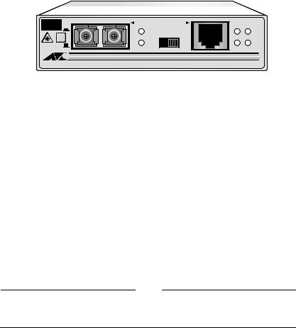
The AT-MC101XL and AT-MC102XL convert IEEE 802.3u 100Base-TX to 100Base-FX multimode Fast Ethernet network connections. The AT-MC103XL and AT-MC103LH convert to FX single mode. The 100Base-FX interfaces are available in ST or SC connectors for multimode fiber cabling. For single mode cabling, the 100Base-FX is available in SC connectors only. The 100Base-TX interface uses an RJ45 shielded connector.
TX |
RX |
100Base-FX |
100Base-TX |
REC |
NML |
|
|
|
|
|
REC |
|
PWR |
|
|
|
|
||
LNK TST |
|
LNK |
|
NML |
|
|
MDI MDI-X |
LNK |
|
|
|
|
MC101XL FAST ETHERNET MEDIA CONVERTER
Figure 1 AT-MC101XL Front Panel (ST multimode connector)
TX |
RX |
100Base-FX 100Base-TX |
|
|
|
REC |
|
NML |
|
|
|
|
REC |
PWR |
|
|
|
||
LNK TST |
|
LNK |
NML |
|
MDI MDI-X |
LNK |
|
|
|
MC102XL FAST ETHERNET MEDIA CONVERTER
Figure 2 AT-MC102XL Front Panel (SC multimode connector)
CLASS 1 |
TX |
RX |
100Base-FX 100Base-TX |
|
LASER LIGHT |
NML |
|
REC |
|
DO NOT STARE |
|
|
||
INTO BEAM |
|
|
REC |
PWR |
|
|
|
||
|
|
|
LNK |
NML |
LNK TST |
|
MDI MDI-X |
LNK |
|
MC103XL SINGLE MODE FIBER FAST ETHERNET MEDIA CONVERTER
Figure 3 AT-MC103XL Front Panel (SC single mode connector)
1
CLASS 1 |
TX |
RX |
100Base-FX 100Base-TX |
|
LASER LIGHT |
NML |
|
REC |
|
DO NOT STARE |
|
|
||
INTO BEAM |
|
|
REC |
PWR |
|
|
|
||
|
|
|
LNK |
NML |
LNK TST |
|
MDI MDI-X |
LNK |
|
MC103LH SINGLE MODE FIBER LONG HAUL FAST ETHERNET MEDIA CONVERTER
Figure 4 AT-MC103LH (SC single mode connector)
Key Features
The media converters have the following key features:
LEDs for unit and port status
MDI/MDI-X Switch
NML/LNK TST Switch
100Base-TX ports participate in auto-negotiation for 100 Mbps and halfor full-duplex modes
MissingLink provides link fault detection on 100Base-TX and 100Base-FX segments
External AC-DC Power Adapter
Standard, compact size for use with AT-MCR12 rack-mount chassis
Low power consumption
Note
For definitions of technical terms associated with Allied Telesyn’s products, refer to the Glossary on our website at www.alliedtelesyn.com.
2

Installation Guide
LEDs
The PWR LED in the upper right corner of the front panel lights when the media converter is receiving power. Status LEDs are located on the front panel next to each port and described in Table 1.
|
|
|
Table 1 LEDs |
|
|
|
|
|
|
LED |
Color |
State |
|
Description |
|
|
|
|
|
|
|
|
|
|
PWR |
Green |
ON |
|
Power is applied. |
|
|
|
|
|
NML |
Green |
ON |
|
Unit is operating in normal mode. |
|
|
OFF |
|
Unit is in Link Test mode. |
|
|
|
|
|
REC |
Green |
ON |
|
Data is being received on the port. |
|
|
|
|
|
LNK |
Green |
ON |
|
Link established on the port. |
|
|
|
|
|
MDI/MDI-X Switch
The MDI/MDI-X (Media Dependent Interface/Media Dependent Interface with Crossover) switch, located on the front panel, is a straight-through or crossover cable selection switch. It enables the RJ45 port to be connected to a repeater or DTE device without using a special crossover cable. The default position of the switch is MDI-X, which means you can connect the RJ45 port to a workstation or to any other DTE device using a straight-through cable.
NML/LNK TST Switch
The NML/LNK TST (Normal/Link Test) switch, located on the front panel, establishes a fiber/twisted pair link in the test position.
The default position of the switch is IN, which is the normal (NML) operating mode and enables the MissingLink feature. With the switch in the OUT or Link Test mode (LNK TST) position, the MissingLink feature is disabled and the optical transmitter TX is forced on. The NML LED lights when the NML/ TST LNK switch is in the default (IN) operating position.
Note
Using the Link Test mode does not interfere with the media converter’s ability to pass network traffic.
3
Auto-Negotiation
The 100Base-TX ports participate in IEEE 802.3u Standard auto-negotiation with its local link partner.
Note
End stations used with the media converter must operate in the same duplex mode (either both full-duplex or both half-duplex).
Note
The media converters have an additional feature, allowing the unit to operate in 100 Mbps half-duplex mode. Certain applications require this mode, for example, two media converters installed in a back-to-back configuration (fiber-to-fiber) which are attached to unmanaged repeaters and/or switches that auto-negotiates with the other. Forinstructions on how to set up the media converter for this application, contact Allied Telesyn Technical Support.
MissingLink
MissingLink gives the host (router, server, switch) attached to each end of the converter critical information about the status of the other (remote) segment link. If either link fails, the converter interacts with both hosts, making each instantly aware of the link fault. Either host can then execute preprogrammed, redundant transmission path selection.
External AC-DC Power Adapter
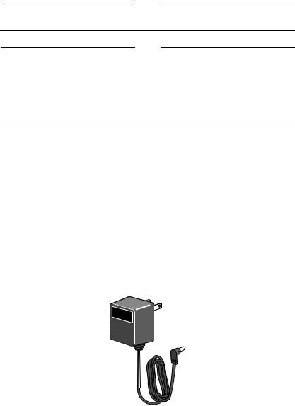
An external AC-to-DC power adapter is included with the fast switch for standalone operation (see Figure 5). The power adapter supplies 12 volts DC to the media converter. Allied Telesyn supplies an approved safety compliant AC power adapter for the 120 and 240 V AC versions with an unregulated output of 12 V DC at 1 A. The power required for the media converter is 12 V DC, 500 mA.
Figure 5 External AC-DC Power Adapter (North American version)
4

Installation Guide
Package Contents
Make sure the media converter package contains the following items:
AT-MC101XL, AT-MC102XL, AT-MC103XL, or AT-MC103LH Fast Ethernet Media Converter
Four Protective Feet (for standalone use only)
External AC-DC Power Adapter
This Installation Guide
Contact your sales representative if any items are missing or damaged.
Installing the Media Converter
Read the warnings below before beginning any installation.
Warning
Do not stare into the laser beam when installing the media converters.
!5
LIGHTNING DANGER: DO NOT WORK on equipment or CABLES during periods of LIGHTNING ACTIVITY!6
DO NOT BLOCK AIR VENTS !7
The following steps are for a standalone installation. To install media converters in a rack mount chassis, see “Rack mount Chassis Installation” on page 7. For information concerning back-to-back converter configuration, see “Back-to-Back Installation” on page 7.
Standalone Installation
1.Remove all equipment from the package and store the packaging in a safe place
2.Attach the four rubber feet to the base of the unit, placing one rubber foot in each corner.For rack-mount installation, do not attach the four rubber feet.
3.Plug the AC-DC power adapter into an appropriate AC power outlet and insert the power plug into the DC receptacle located on the rear panel.
12 V D C 
Figure 6 12 V DC Connector on Rear Panel
5
Loading...