


 Loading...
GS910 Series
GIGABIT ETHERNET UNMANAGED SWITCHES
AT-GS910/5
AT-GS910/5E
AT-GS910/8
AT-GS910/8E
AT-GS910/16
AT-GS910/24
Installation and User’s Guide
613-002143 Rev. B
Copyright 2016 Allied Telesis, Inc.
All rights reserved. No part of this publication may be reproduced without prior written permission from Allied Telesis, Inc.
Microsoft and Internet Explorer are registered trademarks of Microsoft Corporation. Netscape Navigator is a registered trademark of Netscape Communications Corporation. All other product names, company names, logos or other designations mentioned herein are trademarks or registered trademarks of their respective owners.
Allied Telesis, Inc. reserves the right to make changes in specifications and other information contained in this document without prior written notice. The information provided herein is subject to change without notice. In no event shall Allied Telesis, Inc. be liable for any incidental, special, indirect, or consequential damages whatsoever, including but not limited to lost profits, arising out of or related to this manual or the information contained herein, even if Allied Telesis, Inc. has been advised of, known, or should have known, the possibility of such damages.

Electrical Safety and Emissions
Standards
This section contains the following:
“US Federal Communications Commission”
“Industry Canada”
“Emissions, Immunity and Electrical Safety Standards” on page 4
“Translated Safety Statements” on page 4
US Federal Communications Commission
Radiated Energy
Note
This equipment has been tested and found to comply with the limits for a Class A digital device pursuant to Part 15 of FCC Rules. These limits are designed to provide reasonable protection against harmful interference when the equipment is operated in a commercial environment.
This equipment generates, uses, and can radiate radio frequency energy and, if not installed and used in accordance with this instruction manual, may cause harmful interference to radio communications. Operation of this equipment in a residential area is likely to cause harmful interference in which case the user will be required to correct the interference at his own expense.
Note
Modifications or changes not expressly approved of by the manufacturer or the FCC, can void your right to operate this equipment.
Industry Canada
Radiated Energy
This Class A digital apparatus complies with Canadian ICES-003.
Cet appareil numérique de la classe A est conforme à la norme NMB-003 du Canada.
3

Emissions, Immunity and Electrical Safety Standards
RFI Emissions FCC Class A, CISPR 22 Class A, CISPR 32 Class A, EN55022 Class A, EN55032 Class A, VCCI, ICES-3(A)/NMB-3(A)
Warning
In a domestic environment this product may cause radio interference in which case the user may be required to take adequate measures. E84
EMC (Immunity) |
EN55024, EN61000-3-2, EN61000-3-3 |
Electrical Safety |
UL60950-1 (CULUS), UL-CB, UL-EU |
Translated Safety Statements
Important: The indicates that translations of the safety statement are available in the PDF document Translated Safety Statements posted on the Allied Telesis website at alliedtelesis.com/support.
4

Contents
Preface .................................................................................................................................................................................. |
7 |
Safety Symbols Used in this Document .......................................................................................................................... |
8 |
Contacting Allied Telesis ................................................................................................................................................. |
9 |
Chapter 1: Product Description ........................................................................................................................................ |
11 |
Overview ....................................................................................................................................................................... |
12 |
AT-GS910/5 Switch................................................................................................................................................ |
12 |
AT-GS910/5E Switch ............................................................................................................................................. |
13 |
AT-GS910/8 Switch................................................................................................................................................ |
14 |
AT-GS910/8E Switch ............................................................................................................................................. |
14 |
AT-GS910/16 Switch.............................................................................................................................................. |
15 |
AT-GS910/24 Switch.............................................................................................................................................. |
16 |
Wall and Rack Mount Brackets .............................................................................................................................. |
16 |
LEDs ...................................................................................................................................................................... |
17 |
10/100/1000 Base-TX Twisted Pair Ports .............................................................................................................. |
18 |
Power Connector ................................................................................................................................................... |
19 |
Key Features ................................................................................................................................................................. |
20 |
Ethernet Switching Basics............................................................................................................................................. |
21 |
Duplex Mode .......................................................................................................................................................... |
21 |
Store-and- Forward ................................................................................................................................................ |
21 |
Backpressure and Flow Control ............................................................................................................................. |
21 |
Loop Prevention ............................................................................................................................................................ |
23 |
Examples with Multiple Loop Prevention Switches ................................................................................................ |
23 |
Examples with Loop Prevention and Regular Switches......................................................................................... |
24 |
Examples within a Loop Prevention Switch............................................................................................................ |
25 |
Guidelines for Loop Prevention.............................................................................................................................. |
26 |
Enabling Loop Protection ....................................................................................................................................... |
26 |
Disabling Loop Protection ...................................................................................................................................... |
26 |
Energy Efficiency Ethernet (EEE) ................................................................................................................................. |
27 |
Chapter 2: Installation ....................................................................................................................................................... |
29 |
Reviewing Safety Precautions....................................................................................................................................... |
30 |
Selecting a Site for the Switch....................................................................................................................................... |
32 |
Planning the Installation ................................................................................................................................................ |
33 |
Unpacking the Switch.................................................................................................................................................... |
34 |
Installing the Switch on a Table or Desktop .................................................................................................................. |
36 |
Installing the Switch on a Wall....................................................................................................................................... |
37 |
Guidelines for Installing the Switch on a Wall ........................................................................................................ |
37 |
What to Prepare for Installation with Brackets ....................................................................................................... |
39 |
Installing the AT-GS910/5, AT-GS910/8, or AT-GS910/8E Switch on a Wall........................................................ |
39 |
Installing the AT-GS910/16 Switch on a Wall......................................................................................................... |
39 |
Installing the AT-GS910/24 Switch on a Wall......................................................................................................... |
41 |
Installing the Switch in an Equipment Rack................................................................................................................... |
44 |
Guidelines for Installing the Switch in a Rack ........................................................................................................ |
44 |
What to Prepare for Installation in a Rack.............................................................................................................. |
44 |
Installing the AT-GS910/8 or AT-GS910/8E Switch in a Rack............................................................................... |
44 |
Installing the AT-GS910/16 Switch in a Rack......................................................................................................... |
44 |
Installing the AT-GS910/24 Switch in a Rack......................................................................................................... |
46 |
Cabling the Switch......................................................................................................................................................... |
48 |
Powering On the Switch ................................................................................................................................................ |
49 |
Chapter 3: Installation Using the AT-BRKT-J23 Wall Mount Kit ................................................................................... |
51 |
5
Contents |
|
Reviewing Safety Precautions....................................................................................................................................... |
52 |
Unpacking the AT-BRKT-J23 Wall Mount Kit ................................................................................................................ |
53 |
Installing a Switch Using the AT-BRKT-J23 Wall Mount Kit .......................................................................................... |
54 |
What to Prepare ..................................................................................................................................................... |
54 |
Installing a Switch Using the Wall Mount Kit .......................................................................................................... |
54 |
Chapter 4: Installation Using the AT-RKMT-J08 Rack Mount Kit .................................................................................. |
57 |
Reviewing Safety Precautions....................................................................................................................................... |
58 |
Unpacking the AT-RKMT-J08 Rack Mount Kit .............................................................................................................. |
59 |
Installing a Switch Using the AT-RKMT-J08 Rack Mount Kit ........................................................................................ |
61 |
What to Prepare ..................................................................................................................................................... |
61 |
Installing a Switch Using the Rack Mount Kit ......................................................................................................... |
61 |
Chapter 5: Troubleshooting .............................................................................................................................................. |
65 |
Appendix A: Technical Specifications ............................................................................................................................. |
67 |
Physical Specifications .................................................................................................................................................. |
67 |
Environmental Specifications......................................................................................................................................... |
67 |
Safety and Electromagnetic Emissions Certifications.................................................................................................... |
68 |
Power Specifications ..................................................................................................................................................... |
68 |
RJ-45 Twisted Pair Port Connectors ............................................................................................................................. |
69 |
6

Preface
This manual is the installation and user’s guide for the GS910 Series Gigabit Ethernet Unmanaged Switches. The switch models included in this manual are:
AT-GS910/5
AT-GS910/5E
AT-GS910/8
AT-GS910/8E
AT-GS910/16
AT-GS910/24
This Preface contains the following sections:
“Safety Symbols Used in this Document” on page 8
“Contacting Allied Telesis” on page 9
7

GS910 Series Gigabit Ehternet Unmanaged Switch Installation and User’s Guide
Safety Symbols Used in this Document
This document uses the following conventions:
Note
Notes provide additional information.
Caution
Cautions inform you that performing or omitting a specific action may result in equipment damage or loss of data.
Warning
Warnings inform you that performing or omitting a specific action may result in bodily injury.
8

Preface
Contacting Allied Telesis
If you need assistance with this product, you may contact Allied Telesis technical support by going to the Support & Services section of the Allied Telesis web site at www.alliedtelesis.com/support. You can find links for the following services on this page:
24/7 Online Support - Enter our interactive support center to search for answers to your questions in our knowledge database, check support tickets, learn about Return Merchandise Authorization (RMA), and contact Allied Telesis technical experts.
USA and EMEA phone support - Select the phone number that best fits your location and customer type.
Hardware warranty information - Learn about Allied Telesis warranties and register your product online.
Replacement Services - Submit an RMA request via our interactive support center.
Documentation - View the most recent installation guides, user guides, software release notes, white papers and data sheets for your product.
Software Updates - Download the latest software releases for your product.
For sales or corporate contact information, go to
www.alliedtelesis.com/purchase and select your region.
9
GS910 Series Gigabit Ehternet Unmanaged Switch Installation and User’s Guide
10
Chapter 1
Product Description
This chapter contains the follows sections:
“Overview” on page 12
“Key Features” on page 20
“Ethernet Switching Basics” on page 21
“Loop Prevention” on page 23
“Energy Efficiency Ethernet (EEE)” on page 27
11

GS910 Series Gigabit Ehternet Unmanaged Switch Installation and User’s Guide
Overview
AT-GS910/5
Switch
The GS910 Series Gigabit Ethernet Switch is an eco-friendly unmanaged Gigabit Ethernet switch with 10/100/1000 Mbps twisted-pair ports. The GS910 series switch provides a simple solution to integrate 10, 100, and 1000Mbps devices that exist in your network and expand the network to Gigabit speed.
The eco-friendly feature automatically saves power consumption on each port when the port has not established a link. In addition, the switch does not require software configuration or management.
The GS910 Series Gigabit Ethernet Switch includes the following models:
“AT-GS910/5 Switch”
“AT-GS910/5E Switch”
“AT-GS910/8 Switch” on page 14
“AT-GS910/8E Switch” on page 14
“AT-GS910/16 Switch” on page 15
“AT-GS910/24 Switch” on page 16
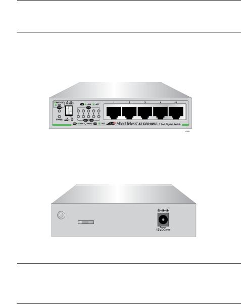
The AT-GS910/5 switch has five 10/100/1000Base-TX twisted pair ports on the front panel as shown in Figure 1.
x
Figure 1. AT-GS910/5 Front Panel
The AT-GS910/5 switch has an internal power supply with a single AC power supply socket on the rear panel as shown in Figure 2.
x
Figure 2. AT-GS910/5 Rear Panel
12
AT-GS910/5E
Switch
Chapter 1: Product Description
The AT-GS910/5 switch can be installed on a desktop or mounted on a wall. To mount the switch on a wall, use the AT-BRKT-J23 wall mount brackets.
Note
The AT-BRKT-J23 wall mount brackets are not included in the shipping box. You must purchase them separately.
The AT-GS910/5E switch has five 10/100/1000Base-TX twisted pair ports on the front panel as shown in Figure 3. The switch is installed on a desktop only.
x
Figure 3. AT-GS910/5E Front Panel
The AT-GS910/5E switch has an external power supply with a single DC power supply socket on the rear panel as shown in Figure 4.
x
Figure 4. AT-GS910/5E Rear Panel
Note
The AT-GS910/5E power receptacle has a twist-and-lock barrel, which is locked by turning the power cord clockwise one-quarter turn.
13
GS910 Series Gigabit Ehternet Unmanaged Switch Installation and User’s Guide
AT-GS910/8
Switch
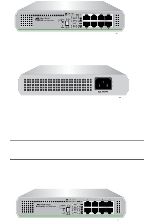
The AT-GS910/8 switch has eight 10/100/1000Base-TX twisted pair ports on the front panel as shown in Figure 5.
x
Figure 5. AT-GS910/8 Front Panel
The AT-GS910/8 switch has an internal power supply with a single AC power supply socket on the rear panel as shown in Figure 6.
x
Figure 6. AT-GS910/8 Rear Panel
AT-GS910/8E
Switch
The AT-GS910/8 switch can be installed on a desktop, mounted on a wall, or mounted in a 19-inch equipment rack. To mount the switch on a wall, use the AT-BRKT-J23 wall mount brackets. To install the switch in an equipment rack, use the AT-RKMT-J08 rack mount brackets.
Note
The AT-BRKT-J23 and AT-RKMT-J08 brackets are not included in the shipping box. You must purchase them separately.
The AT-GS910/8E switch has eight 10/100/1000Base-TX twisted pair ports on the front panel as shown in Figure 7. The switch is installed on a desktop only.
x
Figure 7. AT-GS910/8E Front Panel
14

AT-GS910/16
Switch
Chapter 1: Product Description
The AT-GS910/8E switch has an external power supply with a single DC power supply socket on the rear panel as shown in Figure 8.
x
Figure 8. AT-GS910/8E Rear Panel
Note
The AT-GS910/8E power receptacle has a twist-and-lock barrel which is locked by turning the power cord clockwise one-quarter turn.
The AT-GS910/8E switch can be installed on a desktop, mounted on a wall, or mounted in a 19-inch equipment rack. To mount the switch on a wall, use the AT-BRKT-J23 wall mount brackets. To install the switch in an equipment rack, use the AT-RKMT-J08 rack mount brackets.
Note
The AT-BRKT-J23 and AT-RKMT-J08 brackets are not included in the shipping box. You must purchase them separately.
The AT-GS910/16 switch has 16 10/100/1000Base-TX twisted pair ports on the front panel as shown in Figure 9.
x
Figure 9. AT-GS910/16 Front Panel
The AT-GS910/16 switch has an internal power supply with a single AC power supply socket on the rear panel as shown in Figure 10.
x
Figure 10. AT-GS910/16 Rear Panel
15

GS910 Series Gigabit Ehternet Unmanaged Switch Installation and User’s Guide
AT-GS910/24
Switch
The AT-GS910/16 switch can be installed on a desktop, mounted on a wall, or mounted in a 19-inch equipment rack. To mount the switch on the wall or in an equipment rack, use the brackets that come with the switch.
The AT-GS910/24 switch has 24 10/100/1000Base-TX twisted pair ports on the front panel as shown in Figure 11.
x
Figure 11. AT-GS910/24 Front Panel
The AT-GS910/24 switch has an internal power supply with a single AC power supply socket on the rear panel as shown in Figure 12.
x
Figure 12. AT-GS910/24 Rear Panel
Wall and Rack
Mount Brackets
The AT-GS910/24 switch can be installed on a desktop, mounted on a wall, or mounted in a 19-inch equipment rack. To mount the switch on the wall or in an equipment rack, use the brackets that come with the switch.
Table 1 shows brackets options for the GS910 series switches.
Table 1. Wall and Rack Mount Brackets
Model |
Wall Mount |
Rack Mount |
|
|
|
|
|
|
AT-GS910/5 |
AT-BRKT-J23 |
N/A |
|
|
|
AT-GS910/5E |
N/A |
N/A |
|
|
|
AT-GS910/8 |
AT-BRKT-J23 |
AT-RKMT-J08 |
|
|
|
AT-GS910/8 |
AT-BRKT-J23 |
AT-RKMT-J08 |
|
|
|
AT-GS910/16 |
The brackets in the |
The brackets in the |
|
shipping box |
shipping box |
|
|
|
AT-GS910/24 |
The brackets in the |
The brackets in the |
|
shipping box |
shipping box |
|
|
|
16
Chapter 1: Product Description
LEDs The LEDs on the front panel of the GS910 series switch display status information.
LEDs for the AT-GS910/5 and AT-GS910/5 E Switches
Table 2 describes the LEDs on the AT-GS910/5 and AT-GS910/5E switches.
Table 2. LEDs for the AT-GS910/5 and AT-GS910/5E
LED |
State |
Description |
|
|
|
|
|
|
|
|
|
POWER |
Green |
The switch is powered ON and operating |
|
|
|
normally. |
|
|
|
|
|
|
Off |
The switch is not receiving power. |
|
|
|
|
|
LOOP |
Green |
The Loop Prevention is enabled. |
|
|
|
|
|
|
Blinking |
A loop has been detected and the switch |
|
|
Green |
blocks the looped port to stop the loop. |
|
|
|
|
|
|
Off |
The Loop Prevention is disabled. |
|
|
|
|
|
L/A |
Green |
A valid link is established on the port. |
|
|
|
|
|
|
Blinking |
Frames are being transmitted/received on the |
|
|
Green |
port. |
|
|
|
|
|
|
Off |
No link is established. |
|
|
|
|
|
SPD/ |
Green |
The port is operating at 1000Mbps. |
|
LOOP |
|
|
|
Off |
The port is operating at 10/100Mbps or no link |
||
|
|||
|
|
is established. |
|
|
|
|
|
|
Blinking |
A loop is detected while the port is operating at |
|
|
Green |
10/100/1000Mbps. The switch blocks the |
|
|
|
looped port to stop the loop. |
|
|
|
|
LEDs for the AT-GS910/8, AT-GS910/8E, AT-GS910/16, and AT-GS910/24 Switches
Table 3 on page 18 describes the LEDs on the AT-GS910/8,
AT-GS910/8E, AT-GS910/16, and AT-GS910/24 switches.
17
GS910 Series Gigabit Ehternet Unmanaged Switch Installation and User’s Guide
10/100/1000 Base-TX Twisted Pair Ports
Table 3. LEDs for the AT-GS910/8, AT-GS910/8E, AT-GS910/16, and AT-GS910/24 Switches
LED |
State |
Description |
|
|
|
|
|
|
|
|
|
PWR |
Green |
The switch is powered ON and operating |
|
|
|
normally. |
|
|
|
|
|
|
Off |
The switch is not receiving power. |
|
|
|
|
|
LOOP |
Green |
The Loop Prevention is enabled. |
|
|
|
|
|
|
Blinking |
A loop has been detected and the switch |
|
|
Green |
blocks the looped port to stop the loop. |
|
|
|
|
|
|
Off |
The Loop Prevention is disabled. |
|
|
|
|
|
L/A |
Green |
A valid link is established on the port. |
|
|
|
|
|
|
Blinking |
Frames are being transmitted/received on the |
|
|
Green |
port. |
|
|
|
|
|
|
Off |
No link is established. |
|
|
|
|
|
SPD/ |
Green |
The port is operating at 1000Mbps. |
|
LOOP |
|
|
|
Amber |
The port is operating at 100Mbps. |
||
|
|||
|
|
|
|
|
Off |
The port is operating at 10Mbps or no link is |
|
|
|
established. |
|
|
|
|
|
|
Blinking |
A loop is detected while the port is operating at |
|
|
Green |
1000Mbps. The switch blocks the looped port |
|
|
|
to stop the loop. |
|
|
|
|
|
|
Blinking |
A loop is detected while the port is operating at |
|
|
Amber |
10/100Mbps. The switch blocks the looped port |
|
|
|
to stop the loop. |
|
|
|
|
The GS910 series switch is equipped with multiple 10/100/1000Base-TX twisted pair ports
Connector
All twisted pair ports feature 8-pin RJ-45 connectors. For the port pinouts, see “RJ-45 Twisted Pair Port Connectors” on page 69.
Speed
The ports are 10Base-T, 100Base-TX, and 1000Base-T compliant and capable of 10 Mbps, 100 Mbps, and 1000 Mbps speeds. The ports are IEEE 802.3u Auto-Negotiation compliant. With Auto-Negotiation, the switch automatically matches the highest possible common speed between the switch port and its end-node.
18

Chapter 1: Product Description
For example, if an end-node is capable of only 10 Mbps, the switch sets the port connected to the end-node to 10 Mbps.
Duplex Mode
Each twisted pair port on the switch can operate in either halfor full-duplex mode. The twisted pair ports are IEEE 802.3u-compliant and automatically negotiate the duplex mode setting.
Note
In order for the switch to set the duplex mode for each port correctly, the end-nodes that you connect to the switch ports also need to be configured for Auto-Negotiation. Otherwise, a duplex mode mismatch can occur, affecting network performance. For further information, refer to “Duplex Mode” on page 21.
Cabling
Table 4 contains the cabling specifications for the twisted pair ports.
Table 4. Twisted Pair Cabling and Distances
|
|
Maximum |
Speed |
Type of Cable |
Operating |
|
|
Distance |
|
|
|
10 Mbps |
Two-pair Category 3 or better |
100 m (328 ft) |
|
unshielded twisted pair cable |
|
|
|
|
100 Mbps |
Two-pair Category 5 unshielded |
100 m (328 ft) |
|
twisted pair cable |
|
|
|
|
1000 Mbps |
Four-pair Category 5e unshielded |
100 m (328 ft) |
|
twisted pair cable |
|
|
|
|
Auto MDI/MDI-X
All of the twisted pair ports on the switch feature auto-MDI to automatically configure themselves as MDI or MDI-X when connected to an end-node. Consequently, you can use a straight-through twisted pair cable to connect any network device to a port.
Power Connector The AT-GS910/5, AT-GS910/8, AT-GS910/16, and AT-GS910/24 switches have a single AC power supply socket on the back panel. The AT-GS910/5E and AT-GS910/8E switches have a single DC power supply socket on the back panel. Use the power adapter that came with the switch.
To power ON or OFF the switch, connect or disconnect the power cord.
19

GS910 Series Gigabit Ehternet Unmanaged Switch Installation and User’s Guide
Key Features
The GS910 series switches have the following key features:
10/100/1000 Mbps twisted pair ports with RJ-45 connectors
IEEE802.3 compliant for 10Base-T
IEEE802.3u compliant for 100Base-TX
IEEE802.3ab compliant for 1000Base-T
Auto-Negotiation (IEEE 802.3u-compliant) on all ports
Auto MDI/MDI-X on all ports
Store-and-forward switching method
IEEE 802.3x flow control for full-duplex operation
Back pressure flow control for half-duplex operation
Head-of-line blocking
Jumbo frames of 9216 bytes without frame loss for the AT-GS910/5, AT-GS910/5E, AT-GS910/8 and AT-GS910/8E switches
Jumbo frames of 10K bytes without frame loss for the AT-GS910/16 and AT-GS910/24 switches
Storage of up to 2K MAC addresses for the AT-GS910/5 and AT-GS910/5E switches
Storage of up to 4K MAC addresses for the AT-GS910/8 and AT-GS910/8E switches
Storage of up to 8K MAC addresses for the AT-GS910/16 and AT-GS910/24 switches
BPDU protection from passing through
EAPOL pass-through
Power saving
Loop Prevention that is enabled or disabled from the DIP switch on the front panel
IEEE 802.3az Energy Efficient Ethernet that is enabled or disabled from the DIP switch on the front panel
Diagnostic LEDs
RoHS compliant
12VDC locking power connector for the AT-GS910/5E and AT-GS910/8E switches
20
Chapter 1: Product Description
Ethernet Switching Basics
Duplex Mode
Store-and-
Forward
Backpressure and
Flow Control
An Ethernet switch interconnects network devices, such as workstations, printers, routers, and other Ethernet switches, so that they can communicate with each other by sending and receiving Ethernet frames.
Duplex mode refers to how an end node receives and transmits data. If an end node can receive or transmit data, but not both simultaneously, it is operating in half-duplex mode. If an end node can both receive and transmit data simultaneously, the end node is operating in full-duplex mode. As such an end node capable of operating in full-duplex can handle data much faster than an end node that can only operate in half-duplex mode.
The twisted pair ports on the GS910 series switch can operate in halfor full-duplex mode for 10/100 Mbps. They are IEEE 802.3u-compliant and use Auto-Negotiation to set the duplex mode setting for you automatically.
Note
In order for a switch port to successfully Auto-Negotiate its duplex mode with a 10 or 100 Mbps end-node, the end-node should also be configured for Auto-Negotiation. Otherwise, a duplex mode mismatch can occur. A switch port using Auto-Negotiation defaults to half-duplex if it detects that the end-node is not using Auto-Negotiation. This results in a mismatch if the end-node is operating at a fixed duplex mode of full-duplex.
The GS910 series switch uses store-and-forward as the method for receiving and transmitting frames. When an Ethernet frame is received on a switch port, the switch does not retransmit the frame out the destination port until it has received the entire frame and stored the frame in a port buffer. It then examines the frame to determine if it is a valid frame. Invalid frames, such as fragments or runts, are discarded by the switch. This insures that only valid frames are transmitted out the switch ports and that damaged frames are not propagated on your network.
To maintain the orderly movement of data between the end-nodes, an Ethernet switch may periodically need to signal an end-node to stop sending data. This can occur under several circumstances. For example, if two end-nodes are operating at different speeds, the switch, while transferring data between the end-nodes, might need to instruct the faster end-node to stop transmitting data to allow the slower end-node to catch up. An example of this would be when a server operating at 100 Mbps is sending data to a workstation operating at only 10 Mbps.
21
Loading...