


 Loading...
Fast Ethernet
Switch
AT-FS716L
Installation Guide
PN 613-000552 Rev A
Copyright © 2006 Allied Telesis, Inc.
www.alliedtelesis.com
All rights reserved. No part of this publication may be reproduced without prior written permission from Allied Telesis, Inc.
All other product names, company names, logos or other designations mentioned herein are trademarks or registered trademarks of their respective owners.
Allied Telesis, Inc. reserves the right to make changes in specifications and other information contained in this document without prior written notice. The information provided herein is subject to change without notice. In no event shall Allied Telesis, Inc. be liable for any incidental, special, indirect, or consequential damages whatsoever, including but not limited to lost profits, arising out of or related to this manual or the information contained herein, even if Allied Telesis, Inc. has been advised of, known, or should have known, the possibility of such damages.

Electrical Safety and Emissions
Standards
This product meets the following standards.
|
U.S. Federal Communications Commission |
Declaration of Conformity |
|
Manufacturer Name: |
Allied Telesis, Inc. |
Declares that the product: |
Fast Ethernet Switch |
Model Number: |
AT-FS716L |
This product complies with FCC Part 15B, Class B Limits:
This device complies with part 15 of the FCC Rules. Operation is subject to the following two conditions: (1) This device must not cause harmful interference, and (2) this device must accept any interference received, including interference that may cause undesired operation.
Radiated Energy
Note: This equipment has been tested and found to comply with the limits for a Class B digital device pursuant to Part 15 of FCC Rules. These limits are designed to provide reasonable protection against harmful interference in a residential installation. This equipment generates, uses and can radiate radio frequency energy and, if not installed and used in accordance with instructions, may cause harmful interference to radio or television reception, which can be determined by turning the equipment off and on. The user is encouraged to try to correct the interference by one or more of the following measures:
-Reorient or relocate the receiving antenna.
-Increase the separation between the equipment and the receiver.
-Connect the equipment into an outlet on a circuit different from that to which the receiver is connected.
-Consult the dealer or an experienced radio/TV technician for help.
Changes and modifications not expressly approved by the manufacturer or registrant of this equipment can void your authority to operate this equipment under Federal Communications Commission rules.
Industry Canada
This Class B digital apparatus meets all requirements of the Canadian Interference-Causing Equipment Regulations. Cet appareil numérique de la classe B respecte toutes les exigences du Règlement sur le matériel brouilleur du Canada.
3
Electrical Safety and Emissions Standards
EMI |
FCC Class B, CISPR 22 Class B, EN55022 Class B, C-TICK, CE |
Immunity |
EN55024 |
Electrical Safety |
UL 60950 (CULUS), EN60950 (TUV) |
4

AT-FS716L Fast Ethernet Switch Installation Guide
Translated Safety Statements
Important: Appendix B contains translated safety statements for installing this equipment. When you see the , go to Appendix B for the translated safety statement in your language.
Wichtig: Anhang B enthält übersetzte Sicherheitshinweise für die Installation dieses Geräts. Wenn Sie sehen, schlagen Sie in Anhang B den übersetzten Sicherheitshinweis in Ihrer Sprache nach.
Importante: El Apéndice B contiene mensajes de seguridad traducidos para la instalación de este equipo. Cuando vea el símbolo , vaya al Apéndice B para ver el mensaje de seguridad traducido a su idioma.
Important : L'annexe B contient les instructions de sécurité relatives à l'installation de cet équipement. Lorsque vous voyez le symbole , reportez-vous à l'annexe B pour consulter la traduction de ces instructions dans votre langue.
Importante: l’Appendice B contiene avvisi di sicurezza tradotti per l’installazione di questa apparecchiatura. Il simbolo , indica di consultare l’Appendice B per l’avviso di sicurezza nella propria lingua.
Важно: Приложение B содержит переведенную инструкцию по безопасности при установке данного устройства. Если Вы встретите , перейдите к Приложению B для получения переведенной инструкции по безопасности.
5

Contents
Electrical Safety and Emissions Standards ................................................................................................................... |
3 |
Preface ............................................................................................................................................................................... |
8 |
How This Guide is Organized.............................................................................................................................................. |
8 |
Document Conventions ....................................................................................................................................................... |
9 |
Contacting Allied Telesis ................................................................................................................................................... |
10 |
Online Support ........................................................................................................................................................... |
10 |
Email and Telephone Support.................................................................................................................................... |
10 |
Returning Products..................................................................................................................................................... |
10 |
For Sales or Corporate Information............................................................................................................................ |
10 |
Chapter 1 |
|
Product Description ....................................................................................................................................................... |
11 |
Overview............................................................................................................................................................................ |
12 |
Key Features ..................................................................................................................................................................... |
13 |
Standards .......................................................................................................................................................................... |
13 |
Hardware Feature Description........................................................................................................................................... |
14 |
10/100Base-TX Twisted Pair Ports ............................................................................................................................ |
14 |
LEDs........................................................................................................................................................................... |
15 |
AC Power Connector.................................................................................................................................................. |
16 |
A Few Ethernet Switching Basics...................................................................................................................................... |
17 |
MAC Address Table ................................................................................................................................................... |
17 |
Duplex Mode .............................................................................................................................................................. |
18 |
Store and Forward...................................................................................................................................................... |
18 |
Backpressure and Flow Control ................................................................................................................................. |
18 |
Network Topologies........................................................................................................................................................... |
20 |
Standalone Topology ................................................................................................................................................. |
20 |
Cascade Topology ..................................................................................................................................................... |
21 |
Chapter 2 |
|
Installation ....................................................................................................................................................................... |
22 |
Reviewing Safety Precautions........................................................................................................................................... |
23 |
Selecting a Site for the Switch........................................................................................................................................... |
24 |
Planning the Installation .................................................................................................................................................... |
25 |
Unpacking the Switch ........................................................................................................................................................ |
26 |
Installing the Switch on a Table or Desktop....................................................................................................................... |
27 |
Installing the Switch in a Rack........................................................................................................................................... |
29 |
Wall-Mounting the Switch .................................................................................................................................................. |
30 |
Cabling the Switch............................................................................................................................................................. |
32 |
Powering On the Switch .................................................................................................................................................... |
33 |
Chapter 3 |
|
Troubleshooting ............................................................................................................................................................. |
34 |
Appendix A |
|
Technical Specifications ................................................................................................................................................ |
35 |
Physical Specifications ...................................................................................................................................................... |
35 |
Environmental Specifications............................................................................................................................................. |
35 |
Power Specifications ......................................................................................................................................................... |
35 |
Safety and Electromagnetic Emissions Certifications........................................................................................................ |
36 |
Compliance Standards ...................................................................................................................................................... |
36 |
RJ-45 Twisted Pair Port Connectors ................................................................................................................................. |
37 |
6
|
AT-FS716L Fast Ethernet Switch Installation Guide |
Appendix B |
|
Translated Safety Statements |
....................................................................................................................................... 38 |
7

Preface
This guide contains the hardware installation instructions for the
AT-FS716L Fast Ethernet switch.
How This Guide is Organized
This guide contains the following chapters and appendices:
Chapter 1, ”Product Description” on page 11
Chapter 2, ”Installation” on page 22
Chapter 3, ”Troubleshooting” on page 34
Appendix A, ”Technical Specifications” on page 35
Appendix B, ”Translated Safety Statements” on page 38
This preface contains the following sections:
“How This Guide is Organized” on page 8
“Document Conventions” on page 9
“Contacting Allied Telesis” on page 10
8
AT-FS716L Fast Ethernet Switch Installation Guide
Document Conventions
This document uses the following conventions to highlight important information:
Note
Notes provide additional information.
Warning
Warnings inform you that performing or omitting a specific action may result in bodily injury.
Caution
Cautions inform you that performing or omitting a specific action may result in equipment damage or loss of data.
9

Preface
Contacting Allied Telesis
Online Support
Email and
Telephone
Support
Returning
Products
For Sales or Corporate Information
This section provides Allied Telesis contact information for technical support as well as sales or corporate information.
You can request technical support online by accessing the Allied Telesis Knowledge Base from the following web site: http://www.alliedtelesis.com/support/kb.aspx. You can use the Knowledge Base to submit questions to our technical support staff and review answers to previously asked questions.
For Technical Support via email or telephone, refer to the Allied Telesis web site: http://www.alliedtelesis.com. Select your country from the list displayed on the website. Then select the appropriate menu tab.
Products for return or repair must first be assigned a Return Materials Authorization (RMA) number. A product sent to Allied Telesis without a RMA number will be returned to the sender at the sender’s expense.
To obtain a RMA number, contact Allied Telesis’ Technical Support at our web site: http://www.alliedtelesis.com. Select your country from the list displayed on the website. Then select the appropriate menu tab.
You can contact Allied Telesis for sales or corporate information at our web site: http://www.alliedtelesis.com. Select your country from the list displayed on the website. Then select the appropriate menu tab.
10
Chapter 1
Product Description
This chapter contains the follows sections:
“Overview” on page 12
“Key Features” on page 13
“Standards” on page 13
“Hardware Feature Description” on page 14
“A Few Ethernet Switching Basics” on page 17
“Network Topologies” on page 20
11
Chapter 1: Product Description
Overview
The AT-FS716L switch is an unmanaged sixteen-port Fast Ethernet switch.
This switch offers a range of features and capabilities that can be used in a variety of network configurations and topologies, such as:
Creating small workgroups with dedicated 10 megabits per second (Mbps) and 100 Mbps links to your network devices, such as workstations, servers, printers, and routers.
Interconnecting Ethernet hubs or switches to provide a bridge between the different workgroups of your network.
Connecting to other Ethernet switches so that they can be part of a larger Ethernet network.
Maximizing your existing network by providing full-duplex operation over a twisted pair port.
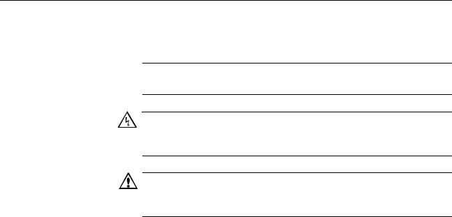
Figure 1 illustrates the front panel of the AT-FS716L switch.
1 |
3 |
5 |
7 |
9 |
11 |
13 |
15 |
AT-FS716L |
|
1 |
3 |
5 |
7 |
9 |
11 |
13 |
15 |
||
16 Port 10/100 Mbps Fast Ethernet Switch |
|
|
|
|
|
|
|
|
|
||
|
|
|
|
|
|
|
|
|
|
||
|
PORT ACTIVITY |
|
|
|
|
|
|
|
|||
100 LINK |
ACT |
10 LINK ACT |
|
|
|
|
|
|
|
||
FDX |
HDX |
COL |
|
|
|
|
|
|
|
||
|
|
|
|
POWER |
|
|
|
|
|
|
|
|
|
|
2 |
4 |
6 |
8 |
10 |
12 |
14 |
16 |
|
2 |
4 |
6 |
8 |
10 |
12 |
14 |
16 |
1010
Figure 1. AT-FS716L Front Panel
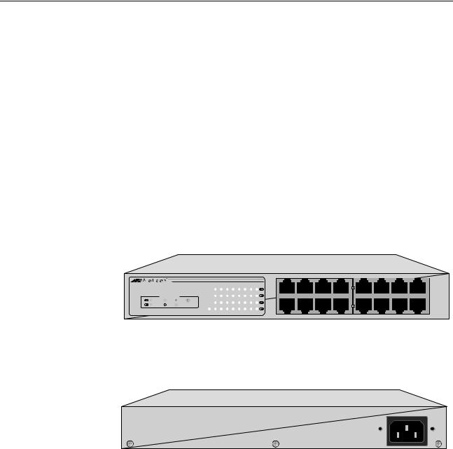
Figure 2 illustrates the back panel of the AT-FS716L switch.
100-240V~ 50-60Hz 0.5A
1011
Figure 2. AT-FS716L Back Panel
The AT-FS716L switch features sixteen 10/100 Mbps ports with RJ-45 connectors. Each twisted pair port has an RJ-45 connector with a maximum operating distance of 100 meters (328 feet). The twisted pair port can operate at 10 Mbps or 100 Mbps, and in halfor full-duplex mode.
The AT-FS716L switch can be used on a desktop, or mounted to a wall or in a rack. The switch is easy to install and does not require software configuration or management.
12

AT-FS716L Fast Ethernet Switch Installation Guide
Key Features
The AT-FS716L switch has the following key features:
Sixteen 10/100 Mbps (10Base-T / 100Base-TX) twisted pair ports with RJ-45 connectors
System and port LEDs
Auto MDI/MDI-X on all 10/100 Mbps twisted pair ports
Support halfor full-duplex mode on all 10/100 Mbps twisted pair ports
Auto-Negotiation (IEEE 802.3u-compliant)
Flow control (IEEE 802.3x-compliant)
Store-and-forward packet forwarding
Storage up to 8K MAC addresses
For use on a desktop, on a wall, or in a rack
RoHS Compliant
Standards
IEEE 802.3 – Ethernet
IEEE 802.3i – 10Base-T
IEEE 802.3u – 100Base-TX
IEEE 802.3x – Flow Control, Symmetric and Asymmetric
13

Chapter 1: Product Description
Hardware Feature Description
10/100Base-TX Twisted Pair Ports
The below sections describe the hardware features of the AT-FS716L Fast Ethernet switch:
Sixteen 10/100 Mbps twisted pair ports
System and port LEDs
AC power connector
The AT-FS716L Fast Ethernet switch features sixteen twisted pair ports. The features of the twisted pair ports are explained in the following sections.
Type of Connector
All twisted pair ports feature 8-pin RJ-45 connectors. (For the port pinouts, refer to “RJ-45 Twisted Pair Port Connectors” on page 37.
Speed
The ports are 10Base-T, and 100Base-T compliant and are capable of 10 megabits per second (Mbps) and 100 Mbps speeds. The ports are IEEE 802.3u Auto-Negotiation compliant. With Auto-Negotiation, the switch automatically matches the highest possible common speed between each switch port and each end-node. For example, if an end-node is capable of only 10 Mbps, the switch sets the port connected to the end-node to 10 Mbps.
Duplex Mode
Each twisted pair port on the switch can operate in either halfor fullduplex mode. The twisted pair ports are IEEE 802.3u-compliant and will Auto-Negotiate the duplex mode setting.
Note
In order for the switch to set the duplex mode for each port correctly, the end-nodes that you connect to the switch ports should also use Auto-Negotiation. Otherwise, a duplex mode mismatch can occur, affecting network performance. For further information, refer to “Duplex Mode” on page 18.
14
AT-FS716L Fast Ethernet Switch Installation Guide
Type of Cabling
For 10 Mbps operation, Category 3 or better 100 ohm shielded or unshielded twisted pair cabling is required. For 100 Mbps operation, Category 5 and Enhanced Category 5 (5E) 100 ohm shielded or unshielded twisted pair cabling is required.
Maximum Distance
Each twisted pair port has a maximum operating distance of 100 meters (328 feet).
Auto MDI/MDI-X
All of the twisted pair ports on the switch are auto-MDI and IEEE 802.3abcompatible. The ports use the auto-MDI feature to automatically configure themselves as MDI or MDI-X when connected to an end-node.
Consequently, you can use a straight-through twisted pair cable to connect any network device to a port.
LEDs The system and port LEDs on the front panel of the AT-FS716L switch display status information. Each port has three LEDs.
Table 1 describes the system and port LEDs on the AT-FS716L Fast Ethernet switch.
Table 1. System and Port LEDs
LED |
State |
Description |
|
|
|
|
|
|
POWER |
Green |
The switch is powered ON and operating |
|
|
normally. |
|
|
|
|
OFF |
The switch is not receiving power. |
|
|
|
L/A |
Green |
The port is operating at a speed of 100 |
|
|
Mbps. |
|
|
|
|
Orange |
The port is operating at a speed of 10 |
|
|
Mbps. |
|
|
|
|
OFF |
No link is established on the port. |
|
|
|
D/C |
Green |
The port is operating in full-duplex mode. |
|
|
|
|
Blinking Green |
A collision occurred on the port. |
|
|
|
|
OFF |
The port is operating in half-duplex |
|
|
mode. |
|
|
|
15
Chapter 1: Product Description
AC Power
Connector
The AT-FS716L Fast Ethernet switch has a single AC power supply socket on the back panel, which has an auto-switch AC input. Refer to Appendix A, “Technical Specifications” on page 35, for the input voltage range.
To power ON or OFF the switch, you connect or disconnect the power cord.
16

AT-FS716L Fast Ethernet Switch Installation Guide
A Few Ethernet Switching Basics
MAC Address
Table
An Ethernet switch interconnects network devices, such as workstations, printers, routers, and other Ethernet switches, so that they can communicate with each other by sending and receiving Ethernet frames.
Every hardware device on your network has a unique MAC address. This address is assigned to the device by the device’s manufacturer. For example, when you install a Network Interface Card (NIC) in a computer so that you can connect it to the network, the NIC already has a MAC address assigned to it by its manufacturer.
The AT-FS716L Fast Ethernet switch can contain up to 8K entries in its MAC address table. The switch uses the table to store the MAC addresses of the network end-nodes connected to the ports, along with the port number on which each address was learned.
A switch learns the MAC addresses of the end-nodes by examining the source address of each packet received on a port. It adds the address and port on which the packet was received to the MAC table if the address had not already been entered in the table. The result is a table that contains all the MAC addresses of the devices that are connected to the switch’s ports, and the port number where each address was learned.
When the switch receives a packet, it also examines the destination address and, by referring to its MAC address table, determines the port on which the destination end-node is connected. It then forwards the packet to the appropriate port and on to the end-node. This increases network bandwidth by limiting each frame to the appropriate port when the intended end-node is located, freeing the other switch ports for receiving and transmitting data.
If the switch receives a packet with a destination address that is not in the MAC address table, it floods the packet to all the ports on the switch. If the ports have been grouped into virtual LANs, the switch floods the packet only to those ports which belong to the same VLAN as the port on which the packet was received. This prevents packets from being forwarded into inappropriate LAN segments, increasing network security. When the destination end-node responds, the switch adds its MAC address and port number to the table.
If the switch receives a packet with a destination address that is on the same port on which the packet was received, it discards the packet without forwarding it on to any port. Since both the source end-node and the destination end-node for the packet are located on the same port on the switch, there is no reason for the switch to forward the packet.
17

Chapter 1: Product Description
Duplex Mode
Store and
Forward
Backpressure and
Flow Control
Duplex mode refers to how an end-node receives and transmits data. If an end-node can receive or transmit data, but not both simultaneously, the end-node is operating in what is referred to as half-duplex mode. If an end-node can both receive and transmit data simultaneously, the endnode is said to be operating in full-duplex mode. Naturally, an end-node capable of operating in full-duplex can handle data much faster than an end-node that can only operate in half-duplex mode.
The twisted pair ports on the AT-FS716L switch can operate in halfor fullduplex mode for 10/100 Mbps. They are IEEE 802.3u-compliant and use Auto-Negotiation to set the duplex mode setting for you automatically.
Note
In order for a switch port to successfully Auto-Negotiate its duplex mode with a 10 or 100 Mbps end-node, the end-node should also be configured for Auto-Negotiation. Otherwise, a duplex mode mismatch can occur. A switch port using Auto-Negotiation defaults to half-duplex if it detects that the end-node is not using AutoNegotiation. This results in a mismatch if the end-node is operating at a fixed duplex mode of full-duplex.
An AT-FS716L switch uses store and forward as the method for receiving and transmitting frames. When a Ethernet frame is received on a switch port, the switch does not retransmit the frame out the destination port until it has received the entire frame and stored the frame in a port buffer. It then examines the frame to determine if it is a valid frame. Invalid frames, such as fragments or runts, are discarded by the switch. This insures that only valid frames are transmitted out the switch ports and that damaged frames are not propagated on your network.
To maintain the orderly movement of data between the end-nodes, an Ethernet switch may periodically need to signal an end-node to stop sending data. This can occur under several circumstances. For example, if two end-nodes are operating at different speeds, the switch, while transferring data between the end-nodes, might need to instruct the faster end-node to stop transmitting data to allow the slower end-node to catch up. An example of this would be when a server operating at 100 Mbps is sending data to a workstation operating at only 10 Mbps.
How a switch signals an end-node to stop transmitting data differs depending on the duplex mode of the end-node and switch port. A twisted pair port operating in half-duplex mode stops an end-node from transmitting data by forcing a collision. A collision on an Ethernet network occurs when two end-nodes attempt to transmit data using the same data link at the same time. A collision causes an end-node to stop sending data, wait for a brief period of time, and then retransmit the same data. Once the switch is ready to receive data again, the switch stops forcing collisions. This is referred to as backpressure.
18
AT-FS716L Fast Ethernet Switch Installation Guide
A port operating in full-duplex mode uses PAUSE frames, as specified in the IEEE 802.3x standard, to stop the transmission of data from an endnode. Whenever the switch wants an end-node to stop transmitting data, it issues this frame. The frame instructs the end-node to cease transmission for a period of time specified within the frame. The switch continues to issue PAUSE frames until it is ready again to receive data from the endnode. This is referred to as flow control.
19
Loading...