


 Loading...
GS920 Series
GIGABIT ETHERNET UNMANAGED SWITCHES AT-GS920/24
AT-GS920/16
AT-GS920/8
Installation and User’s Guide
613-002385 Rev A
Copyright 2017 Allied Telesis, Inc.
All rights reserved. No part of this publication may be reproduced without prior written permission from Allied Telesis, Inc.
Microsoft and Internet Explorer are registered trademarks of Microsoft Corporation. Netscape Navigator is a registered trademark of Netscape Communications Corporation. All other product names, company names, logos or other designations mentioned herein are trademarks or registered trademarks of their respective owners.
Allied Telesis, Inc. reserves the right to make changes in specifications and other information contained in this document without prior written notice. The information provided herein is subject to change without notice. In no event shall Allied Telesis, Inc. be liable for any incidental, special, indirect, or consequential damages whatsoever, including but not limited to lost profits, arising out of or related to this manual or the information contained herein, even if Allied Telesis, Inc. has been advised of, known, or should have known, the possibility of such damages.

Electrical Safety and Emissions
Standards
This section contains the following:
“US Federal Communications Commission”
“Industry Canada”
“Translated Safety Statements” on page 4
US Federal Communications Commission
Radiated Energy for the AT-GS920/24
Note
This equipment has been tested and found to comply with the limits for a Class A digital device pursuant to Part 15 of FCC Rules. These limits are designed to provide reasonable protection against harmful interference when the equipment is operated in a commercial environment.
This equipment generates, uses, and can radiate radio frequency energy and, if not installed and used in accordance with this instruction manual, may cause harmful interference to radio communications. Operation of this equipment in a residential area is likely to cause harmful interference in which case the user will be required to correct the interference at his own expense.
Radiated Energy for the AT-GS920/16 and AT-GS920/8
Note
This equipment has been tested and found to comply with the limits for a Class B digital device pursuant to Part 15 of FCC Rules. These limits are designed to provide reasonable protection against harmful interference in a residential installation. This equipment generates, uses and can radiate radio frequency energy and, if not installed and used in accordance with instructions, may cause harmful interference to radio or television reception, which can be determined by turning the equipment off and on. The user is encouraged to try to correct the interference by one or more of the following measures:
•Increase the separation between the equipment and the receiver.
•Connect the equipment into an outlet on a circuit different from that to which the receiver is connected.
•Consult the dealer or an experienced radio/TV technician for help.
3

Industry Canada
Radiated Energy
This Class A digital apparatus complies with Canadian ICES-003.
Cet appareil numérique de la classe A est conforme à la norme NMB-003 du Canada.
This Class B digital apparatus complies with Canadian ICES-003.
Cet appareil numérique de la classe B est conforme à la norme NMB-003 du Canada.
Translated Safety Statements
Important: The indicates that translations of the safety statement are available in the PDF document Translated Safety Statements posted on the Allied Telesis website at alliedtelesis.com/support.
4

Contents
Preface ................................................................................................................................................................................ |
11 |
Safety Symbols Used in this Document......................................................................................................................... |
12 |
Contacting Allied Telesis ............................................................................................................................................... |
13 |
Chapter 1: Product Description ........................................................................................................................................ |
15 |
Key Features ................................................................................................................................................................. |
16 |
GS920 Series Overview ................................................................................................................................................ |
18 |
AT-GS920/24 Switch.............................................................................................................................................. |
18 |
AT-GS920/16 Switch.............................................................................................................................................. |
19 |
AT-GS920/8 Switch................................................................................................................................................ |
19 |
Wall and Rack Mount Brackets .............................................................................................................................. |
20 |
10/100/1000 Base-TX Twisted Pair Ports .............................................................................................................. |
21 |
Power Connector.................................................................................................................................................... |
22 |
Configuration Switches and LED Descriptions .............................................................................................................. |
23 |
Power LED ............................................................................................................................................................. |
23 |
Loop Prevention LED ............................................................................................................................................. |
24 |
Port Mode LEDs ..................................................................................................................................................... |
24 |
Port Status LEDs.................................................................................................................................................... |
25 |
AT-GS920 Feature Descriptions.................................................................................................................................... |
26 |
Duplex Mode .......................................................................................................................................................... |
26 |
Store and Forward.................................................................................................................................................. |
26 |
Multicast Frame Pass-Through .............................................................................................................................. |
27 |
Energy Efficiency Ethernet (EEE)........................................................................................................................... |
27 |
Loop Prevention ..................................................................................................................................................... |
27 |
Flooding.................................................................................................................................................................. |
28 |
Backpressure and Flow Control ............................................................................................................................. |
28 |
Chapter 2: Hardware Installation ...................................................................................................................................... |
31 |
Reviewing Safety Precautions ....................................................................................................................................... |
32 |
Selecting a Site for the Switch ....................................................................................................................................... |
34 |
Planning the Installation................................................................................................................................................. |
35 |
Unpacking the Switch .................................................................................................................................................... |
36 |
AT-GS920/24 Shipping Contents ........................................................................................................................... |
36 |
Unpacking the AT-GS920/24 Bracket Kit ............................................................................................................... |
37 |
AT-GS920/16 Shipping Contents ........................................................................................................................... |
38 |
AT-GS920/8 Shipping Contents ............................................................................................................................. |
39 |
Installing the Switch on a Table or Desktop................................................................................................................... |
40 |
Installing the Switch on a Wall ....................................................................................................................................... |
41 |
Guidelines for Installing the Switch on a Wall......................................................................................................... |
41 |
Items Need for Wall Installation.............................................................................................................................. |
41 |
Wall Installation of AT-GS920/24 ........................................................................................................................... |
42 |
Wall Installation of AT-GS920/16 or AT-GS920/8 .................................................................................................. |
44 |
Installing the Switch in an Equipment Rack................................................................................................................... |
47 |
Guidelines for Installing the Switch in a Rack......................................................................................................... |
47 |
What to Prepare for Installation in a Rack .............................................................................................................. |
47 |
Rack Installation of AT-GS920/24 .......................................................................................................................... |
47 |
Rack Installation of AT-GS920/16 or AT-GS920/8................................................................................................. |
49 |
Cabling the Switch......................................................................................................................................................... |
54 |
Powering On the Switch ................................................................................................................................................ |
55 |
5
Contents |
|
Chapter 3: Switch Configuration ...................................................................................................................................... |
57 |
Configuration Switch and LED Locations ...................................................................................................................... |
58 |
Reset Ports to Factory Default Configuration ................................................................................................................ |
59 |
Feature Configuration.................................................................................................................................................... |
61 |
Multicast Frame Pass-Through .............................................................................................................................. |
61 |
Energy Efficiency Ethernet (EEE)........................................................................................................................... |
64 |
Loop Prevention ..................................................................................................................................................... |
66 |
Flooding.................................................................................................................................................................. |
68 |
Flow Control ........................................................................................................................................................... |
70 |
Ethernet Port Configuration ........................................................................................................................................... |
72 |
ALL Ports Configuration ......................................................................................................................................... |
73 |
EACH Individual Port Configuration ....................................................................................................................... |
75 |
MDI/MCI-X Configuration ....................................................................................................................................... |
76 |
Chapter 4: Troubleshooting .............................................................................................................................................. |
79 |
Appendix A: Technical Specifications ............................................................................................................................. |
81 |
Physical Specifications .................................................................................................................................................. |
81 |
Environmental Specifications......................................................................................................................................... |
81 |
Safety ............................................................................................................................................................................ |
82 |
Electromagnetic Emissions Certifications...................................................................................................................... |
83 |
EMI (Electro Magnetic Interference)....................................................................................................................... |
83 |
ICES-003 Class A or B........................................................................................................................................... |
83 |
EN55032: 2012/AC: 2013 Class A or B ................................................................................................................. |
83 |
CISPR 32 ............................................................................................................................................................... |
83 |
RCM AS/NZS CISPR 32: 2013 .............................................................................................................................. |
83 |
ANATEL ................................................................................................................................................................. |
83 |
Immunity................................................................................................................................................................. |
83 |
Electrical Safety...................................................................................................................................................... |
83 |
EMS (Electromagnetic Susceptibility) EN55024:2010................................................................................................... |
84 |
Power Specifications ..................................................................................................................................................... |
84 |
RJ-45 Twisted Pair Port Connectors ............................................................................................................................. |
85 |
Appendix B: AT-GS920/24 Switch Wall Mount Installation ............................................................................................ |
87 |
Unpacking the AT-BRKT-J22 Wall Mount Kit ................................................................................................................ |
88 |
Installing a Switch Using the AT-BRKT-J22 Wall Mount Kit .......................................................................................... |
89 |
What to Prepare ..................................................................................................................................................... |
89 |
Installing a Switch Using the AT-BRKT-J22 Brackets ............................................................................................ |
89 |
Appendix C: Loop Prevention Feature ............................................................................................................................ |
95 |
Guidelines for Loop Prevention ..................................................................................................................................... |
96 |
Root Switch ................................................................................................................................................................... |
97 |
Root Switch Overview ............................................................................................................................................ |
97 |
Switch Priority......................................................................................................................................................... |
97 |
Root Switch ............................................................................................................................................................ |
97 |
Non-root Switch...................................................................................................................................................... |
97 |
Examples of Selecting a Root Switch..................................................................................................................... |
98 |
Detecting and Blocking a Loop...................................................................................................................................... |
99 |
Loop Detection ....................................................................................................................................................... |
99 |
Blocked Port Selection Criteria............................................................................................................................... |
99 |
Port Blocked Within a LAN ................................................................................................................................... |
100 |
Port Blocked on One Switch................................................................................................................................. |
101 |
Blocking a Port Affected by an External Loop ...................................................................................................... |
102 |
Hop Count Limitation ................................................................................................................................................... |
103 |
6

GS920 Series Gigabit Ehternet Switch Installation and User’s Guide
List of Figures
Figure 1: AT-GS920/24 Front Panel..................................................................................................................................... |
18 |
Figure 2: AT-GS920/24 Rear Panel...................................................................................................................................... |
19 |
Figure 3: AT-GS920/16 Front Panel..................................................................................................................................... |
19 |
Figure 4: AT-GS920/16 Rear Panel...................................................................................................................................... |
19 |
Figure 5: AT-GS920/8 Front Panel....................................................................................................................................... |
20 |
Figure 6: AT-GS920/8 Rear Panel........................................................................................................................................ |
20 |
Figure 7: AT-GS920/8 Front Panel Configuration DIP Switches and LEDs ......................................................................... |
23 |
Figure 8: Installation of Rubber Feet .................................................................................................................................... |
40 |
Figure 9: Removing Feet From the Chassis Bottom............................................................................................................. |
42 |
Figure 10: Attaching the Brackets to the AT-GS920/24 Switch............................................................................................ |
42 |
Figure 11: Marking the Screw Hole Locations...................................................................................................................... |
43 |
Figure 12: Driving the Screws through the Holes ................................................................................................................. |
43 |
Figure 13: Removing the Rubber Feet ................................................................................................................................. |
45 |
Figure 14: Marking the Screw Hole Locations...................................................................................................................... |
45 |
Figure 15: Driving the Screws through the Holes ................................................................................................................. |
46 |
Figure 16: Placing the Switch into the Brackets ................................................................................................................... |
46 |
Figure 17: Attaching the Extension to the Bracket................................................................................................................ |
47 |
Figure 18: Removing Rubber Feet ....................................................................................................................................... |
48 |
Figure 19: Attaching the Brackets to the Switch................................................................................................................... |
48 |
Figure 20: Attaching the Switch to an Equipment Rack........................................................................................................ |
48 |
Figure 21: Attaching Handles to Brackets ............................................................................................................................ |
51 |
Figure 22: Attaching Brackets to Plates................................................................................................................................ |
51 |
Figure 23: Attaching Cable Tray to Plates............................................................................................................................ |
52 |
Figure 24: Attaching the Plates to the Switch....................................................................................................................... |
52 |
Figure 25: Attaching the Switch to Equipment Rack............................................................................................................. |
53 |
Figure 26: Initial Power-ON Sequence ................................................................................................................................. |
55 |
Figure 27: Securing the Power Cord Using Tie-wraps ......................................................................................................... |
56 |
Figure 28: Front Panel Configuration Switches and LEDs ................................................................................................... |
58 |
Figure 29: Setting the Switch to Port Configuration Mode.................................................................................................... |
59 |
Figure 30: DIP Switch Setting for Enabling Multicast Frame Pass-Through ........................................................................ |
62 |
Figure 31: DIP Switch Settings for Disabling Multicast Frame Pass-Through...................................................................... |
63 |
Figure 32: DIP Switch Settings for Enabling EEE................................................................................................................. |
64 |
Figure 33: DIP Switch Settings for Disabling EEE................................................................................................................ |
65 |
Figure 34: DIP Switch Settings for Enabling Loop Prevention.............................................................................................. |
66 |
Figure 35: DIP Switch Settings for Disabling Loop Prevention............................................................................................. |
67 |
Figure 36: DIP Switch Settings for Enabling Flooding.......................................................................................................... |
68 |
Figure 37: DIP Switch Settings for Disabling Flooding ......................................................................................................... |
69 |
Figure 38: DIP Switch Settings for Enabling Flow Control.................................................................................................... |
70 |
Figure 39: DIP Switch Settings for Disabling Flow Control................................................................................................... |
71 |
Figure 40: DIP Switch Settings for Configuring All Ports...................................................................................................... |
73 |
Figure 41: Port Configuration ............................................................................................................................................... |
74 |
Figure 42: DIP Switch Settings for Configuring An Individual Port ....................................................................................... |
75 |
Figure 43: DIP Switch Settings for ALL Port Configuration .................................................................................................. |
77 |
Figure 44: DIP Switch Settings for Individual Port Configuration.......................................................................................... |
78 |
Figure 45: RJ-45 Connector and Port Pin Layout................................................................................................................. |
85 |
Figure 46: Removing AT-GS920/24 Rubber Feet ................................................................................................................ |
89 |
Figure 47: Marking the Screw Hole Locations...................................................................................................................... |
90 |
Figure 48: Driving the Screws through the Holes ................................................................................................................. |
91 |
Figure 49: Placing the Switch into the Brackets ................................................................................................................... |
91 |
Figure 50: Marking the Screw Hole Locations...................................................................................................................... |
92 |
Figure 51: Driving the Screws through the Holes ................................................................................................................. |
93 |
Figure 52: Case 1: Selecting a Root Switch ......................................................................................................................... |
98 |
Figure 53: Case 2: Selecting a Root Switch ......................................................................................................................... |
98 |
Figure 54: Case 1: Selecting a Port to be Blocked............................................................................................................. |
100 |
7
Figures |
|
Figure 55: Case 2: Selecting a Port to be Blocked ............................................................................................................. |
100 |
Figure 56: Case 3: Selecting a Port to be Blocked ............................................................................................................. |
101 |
Figure 57: Blocked Port on One AT-GS920/8 Switch......................................................................................................... |
101 |
Figure 58: Blocked Port on One AT-GS920/16 or AT-GS920/24 Switch............................................................................ |
101 |
Figure 59: Blocking a Port Affected by an External Loop ................................................................................................... |
102 |
8

GS920 Series Gigabit Ehternet Switch Installation and User’s Guide
List of Tables
Table 1. Wall and Rack Mount Brackets ............................................................................................................................. |
20 |
Table 2. Twisted Pair Cabling and Distances ..................................................................................................................... |
22 |
Table 3. Power LED ........................................................................................................................................................... |
23 |
Table 4. Loop Prevention LED ........................................................................................................................................... |
24 |
Table 5. Port Mode LEDs ................................................................................................................................................... |
24 |
Table 6. Port Status LEDs for Normal and Configuration Modes ....................................................................................... |
25 |
Table 7. Flow Control - Supported Speeds ......................................................................................................................... |
29 |
Table 8. Twisted Pair Cabling and Distances ..................................................................................................................... |
35 |
Table 9. AT-GS920/24 Shipping Box Contents .................................................................................................................. |
36 |
Table 10. Components in the AT-GS920/24 Bracket Kit .................................................................................................... |
37 |
Table 11. AT-GS920/16 Shipping Box Contents ................................................................................................................ |
38 |
Table 12. AT-GS920/8 Shipping Box Contents .................................................................................................................. |
39 |
Table 13. Components in the AT-BRKT-J23 Wall Mount Kit .............................................................................................. |
44 |
Table 14. Components in Rack Mount Kit .......................................................................................................................... |
49 |
Table 15. EEE Support for Port Speed/Link Configuration ................................................................................................. |
65 |
Table 16. MDI Pin Signals (10Base-T or 100Base-TX) ...................................................................................................... |
85 |
Table 17. MDI-X Pin Signals (10Base-T or 100Base-TX) .................................................................................................. |
85 |
Table 18. Pin Signals (1000 Mbps) ..................................................................................................................................... |
86 |
Table 19. Components in the AT-BRKT-J22 Wall Mount Kit .............................................................................................. |
88 |
Table 20. Switch Priority ..................................................................................................................................................... |
97 |
Table 21. Maximum Hop Count ........................................................................................................................................ |
103 |
9
Tables
10
Preface
This Preface contains the following sections:
“Safety Symbols Used in this Document” on page 12
“Contacting Allied Telesis” on page 13
This manual is the installation and user’s guide for the GS920 Series Gigabit Ethernet Unmanaged Switches. The switch models included in this manual are:
–AT-GS920/24
–AT-GS920/16
–AT-GS920/8
11

GS920 Series Gigabit Ehternet Switch Installation and User’s Guide
Safety Symbols Used in this Document
This document uses the following conventions:
Note
Notes provide additional information.
Caution
Cautions inform you that performing or omitting a specific action may result in equipment damage or loss of data.
Warning
Warnings inform you that performing or omitting a specific action may result in bodily injury.
12

Preface
Contacting Allied Telesis
If you need assistance with this product, you may contact Allied Telesis technical support by going to the Support & Services section of the Allied Telesis web site at www.alliedtelesis.com/support. You can find links for the following services on this page:
24/7 Online Support - Enter our interactive support center to search for answers to your questions in our knowledge database, check support tickets, learn about Return Merchandise Authorization (RMA), and contact Allied Telesis technical experts.
USA and EMEA phone support - Select the phone number that best fits your location and customer type.
Hardware warranty information - Learn about Allied Telesis warranties and register your product online.
Replacement Services - Submit an RMA request via our interactive support center.
Documentation - View the most recent installation guides, user guides, software release notes, white papers and data sheets for your product.
Software Updates - Download the latest software releases for your product.
For sales or corporate contact information, go to
www.alliedtelesis.com/purchase and select your region.
13
GS920 Series Gigabit Ehternet Switch Installation and User’s Guide
14

Chapter 1
Product Description
This chapter contains the follows sections:
“Key Features” on page 16
“GS920 Series Overview” on page 18
“Configuration Switches and LED Descriptions” on page 23
“AT-GS920 Feature Descriptions” on page 26
15

GS920 Series Gigabit Ehternet Switch Installation and User’s Guide
Key Features
The GS920 Series switches have the following key features:
–Complies with IEEE802.3,IEEE802.3u,IEEE802.3ab, IEEE802.3x
–Supports 8 auto-negotiation 10/100/1000Mbps ports for AT-GS920/8
–Supports 16 auto-negotiation 10/100/1000Mbps ports for AT-GS920/16
–Supports 24 auto-negotiation 10/100/1000Mbps ports for AT-GS920/24
–Supports Store-and-forward packet forwarding
–Supports HOL blocking prevention
–Supports jumbo frames of 9216 bytes (inclusive) without frame loss and drops packets that are larger than 9216 bytes (exclusive)
–MAC address entries:
–AT-GS920/8: up to 4K
–AT-GS920/16: up to 8K
–AT-GS920/24: up to 8K
–Supports link down and cable length power saving function
–Supports Multicast Frame Pass-Through which can be enabled or disabled by setting a DIP switch
–Supports AUTO MDI/MDI-X on all ports. All ports are capable of being configured for Fixed MDI-X except the last port which is configured for Fixed MDI. This feature is enabled and disabled by setting DIP switches and using a front panel push button.
–Supports IEEE 802.3x flow control in full-duplex operation and backpressure flow control in half-duplex operation. This feature is enabled or disabled by setting a DIP switch
–Supports loop detection and prevention function - can be enabled or disabled by setting a DIP switch
–Supports IEEE 802.3az EEE function only for 100M/1000M link speed - can be enabled or disabled by setting a DIP switch (EEE for 10M is not supported)
–Supports Flooding mode - can be enabled or disabled by setting a DIP switch
–Supports port speed and half/full duplex configurable function by setting the DIP switches and using a front panel push button.
–Each chassis has no fan.
–Internal switching power supply
16
Chapter 1: Product Description
–RoHS Compliant
–0 to 50 degree C operating temperature
–Wall/Rack mount kit is provided within the AT-GS920/24 ship kit
–Support both wall mount and rack mount functions for RoW
17

GS920 Series Gigabit Ehternet Switch Installation and User’s Guide
GS920 Series Overview
AT-GS920/24
Switch
The GS920 Series switch includes the following models and hardware features:
“AT-GS920/24 Switch”
“AT-GS920/16 Switch” on page 19
“AT-GS920/8 Switch” on page 19
“Wall and Rack Mount Brackets” on page 20
“10/100/1000 Base-TX Twisted Pair Ports” on page 21
“Power Connector” on page 22
Each model uses an internal high efficiency PSU and a low power chipset to conform with the Allied Telesis commitment to environmentally friendly processes. They can all be installed on a desktop, mounted on a wall or mounted in a 19” rack.
Each switch features support for Multi-Cast Frame Pass-Through, IEEE802.3az Energy Efficiency power savings, Loop Detection and Prevention, Flooding Mode and Flow Control. These features are each configurable by dedicated front panel DIP switches. See “AT-GS920 Feature Descriptions” on page 26 and “Feature Configuration” on page 61 for more information.
In addition, the switch ports can be individually or collectively configured for auto-negotiation or manual duplex and speed settings. The highest number port’s default setting is MDI/MDI-X and can be forced to fixed MDI while all of the other ports can be forced to MDI/MDI-X. These port settings are configured by a combination of the front panel DIP switches and push buttons. See “Ethernet Port Configuration” on page 72 for more information.
The AT-GS920/24 switch can be installed on a desktop, a wall, or in a 19-inch equipment rack. To mount the switch on the wall or in an equipment rack, use the brackets that are provided with the switch.
The AT-GS920/24 switch has 24 each 10/100/1000Base-TX twisted pair ports as shown in Figure 1.
Figure 1. AT-GS920/24 Front Panel
18

AT-GS920/16
Switch
AT-GS920/8
Switch
Chapter 1: Product Description
The AT-GS920/24 switch has an internal power supply with a single AC power supply socket on the rear panel as shown in Figure 2.
x
Figure 2. AT-GS920/24 Rear Panel
The AT-GS920/16 switch can be installed on a desktop, mounted on a wall, or in a 19-inch equipment rack. To mount the switch on the wall or an equipment rack, you must order separate bracket kits. For more information, see Table 1, “Wall and Rack Mount Brackets” on page 20.
The AT-GS920/16 switch has 16 each 10/100/1000Base-TX twisted pair ports on the front panel as shown in Figure 3.
x
Figure 3. AT-GS920/16 Front Panel
The AT-GS920/16 switch has an internal power supply with a single AC power supply socket on the rear panel as shown in Figure 4.
x
Figure 4. AT-GS920/16 Rear Panel
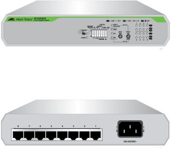
The AT-GS920/8 switch can be installed on a desktop, mounted on a wall, or mounted in a 19-inch equipment rack. To mount the switch on the wall or in an equipment rack, use the brackets that are provided with the switch.
The AT-GS920/8 switch has 8 each 10/100/1000Base-TX twisted pair ports as shown in Figure 5.
19
GS920 Series Gigabit Ehternet Switch Installation and User’s Guide
x
Wall and Rack
Mount Brackets
Figure 5. AT-GS920/8 Front Panel
The AT-GS920/8 switch has an internal power supply with a single AC power supply socket on the rear panel as shown in Figure 6.
x
Figure 6. AT-GS920/8 Rear Panel
Table 1 shows brackets options for the GS920 Series switches.
Table 1. Wall and Rack Mount Brackets
Model |
Wall Mount |
Rack Mount |
|
|
|
|
|
|
AT-GS920/24 |
Use the Wall/Rack |
Use the Wall/Rack Mount |
|
Mount Kit provided in the |
Kit provided in the shipping |
|
shipping box for all |
box for all installations. |
|
installations except in |
|
|
Japan. |
|
|
NOTE: For Japan |
|
|
installations only, use the |
|
|
optional AT-BRKT-J22 |
|
|
Wall Mount Kit instead |
|
|
which must be ordered |
|
|
separately. |
|
|
|
|
AT-GS920/16 |
Use AT-BRKT-J23 wall |
Optional AT-RKMT-J05 |
|
mount kit. |
optional 19” rack mount kit. |
|
NOTE: This kit must be |
NOTE: This kit must be |
|
ordered separately. |
ordered separately. |
|
|
|
AT-GS920/8 |
Use AT-BRKT-J23 wall |
Optional AT-RKMT-J08 |
|
mount kit. |
optional 19” rack mount kit. |
|
NOTE: This kit must be |
NOTE: This kit must be |
|
ordered separately. |
ordered separately. |
|
|
|
20
10/100/1000 Base-TX Twisted Pair Ports
Chapter 1: Product Description
The GS920 Series switches are equipped with multiple 10/100/1000Base-TX twisted pair ports
Connector
All twisted pair ports feature 8-pin RJ-45 connectors. For the port pinouts, see “RJ-45 Twisted Pair Port Connectors” on page 85.
Speed
The ports are 10Base-T, 100Base-TX, and 1000Base-T compliant and capable of 10 Mbps, 100 Mbps, and 1000 Mbps speeds. The ports default configuration is IEEE 802.3u Auto-Negotiation compliant. With Auto-Negotiation enabled, the switch automatically matches the highest possible common speed between the switch port and its end-node. For example, if an end-node is capable of only 10 Mbps, the switch sets the port connected to the end-node to 10 Mbps.
Alternatively, each port can be manually configured to 10 Mbps, 100 Mbps, and 1000 Mbps via the switches and push buttons. See “MDI/MDI-X” for the corresponding description of the MDI-X configuration.
Duplex Mode
Each twisted pair port on the switch can operate in either halfor full-duplex mode at 100/10 Mbps and full-duplex mode only when operating at 1000 Mbps. The duplex default settings of the twisted pair ports are IEEE 802.3u-compliant and automatically negotiate the duplex mode setting.
Note
In order for the switch to automatically set the duplex mode for each port correctly at 100/10 Mbps, the end-nodes that you connect to the switch ports also need to be configured for Auto-Negotiation.
Otherwise, a duplex mode mismatch can occur, affecting network performance. For further information, refer to “Duplex Mode” on page 26.
With the DIP switches and push buttons, each port can be manually configured for one of the following duplex modes: Auto-Negotiation, 1000M/Full, 100M/Full, 100M/Half, 10M/Full, 10M/Half.
21

GS920 Series Gigabit Ehternet Switch Installation and User’s Guide
MDI/MDI-X
The default configuration for all of the twisted pair ports on the switch is auto-MDI/MDI-X where the ports automatically configure themselves as MDI or MDI-X when connected to an end-node. Auto-MDI/MDI-X is in effect when the ports are configured for Auto-Negotiation or 1000M/FULL. In this mode, you can use a straight-through twisted pair cable to connect any network device to a port.
Note
See “Ethernet Port Configuration” on page 72 for the port configuration procedures.
You can manually force the highest numbered port to fixed MDI by using one of the front panel push buttons. When all of the ports are configured at once, then the configuration for all other ports is fixed MDI-X.
When a port is manually configured for a speed of 10M or 100M, then that port is also configured for fixed MDI-X except in the case of the highest numbered port, which is set to fixed MDI.
Cabling
Table 2 contains the cabling specifications for the twisted pair ports.
Table 2. Twisted Pair Cabling and Distances
Speed |
Type of Cable |
Maximum |
Operating |
||
|
|
Distance |
|
|
|
10 Mbps |
Two-pair Category 3 or better |
100 m (328 ft) |
|
unshielded twisted pair cable |
|
|
|
|
100 Mbps |
Two-pair Category 5 or better |
100 m (328 ft) |
|
unshielded twisted pair cable |
|
|
|
|
1000 Mbps |
Four-pair Category 5e or better |
100 m (328 ft) |
|
unshielded twisted pair cable |
|
|
|
|
Power Connector The AT-GS920 switches have a single AC power supply socket on the back panel. Use the AC power cord that is supplied with the switch.
Note
To power the switch ON or OFF, connect or disconnect the power cord from the switch.
22
Chapter 1: Product Description
Configuration Switches and LED Descriptions
The LEDs display status information when the switch is in a Normal operating mode or in a Configuration mode.
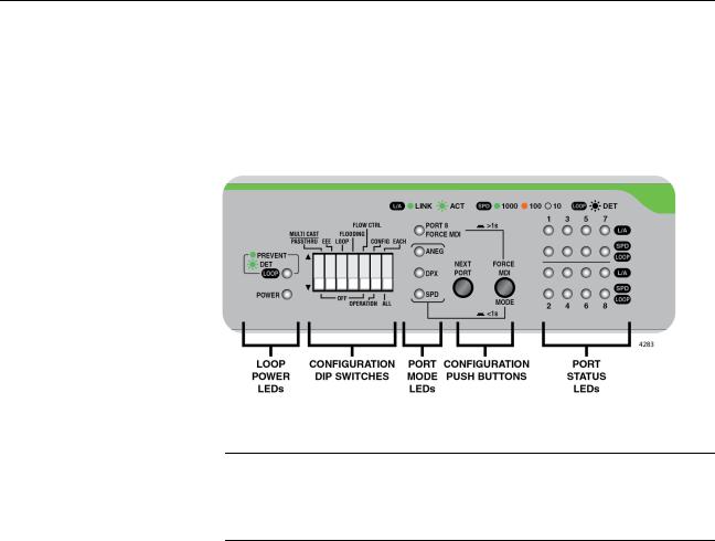
The GS920 Series LEDs and configuration switches are located on the front panel of the chassis. Refer to Figure 7, “AT-GS920/8 Front Panel Configuration DIP Switches and LEDs” for their locations.
Figure 7. AT-GS920/8 Front Panel Configuration DIP Switches and LEDs
Note
The front panel Configuration switches and LED locations are shown for the AT-GS920/8 switch. Similar switch and LED layouts can also be found on the AT-GS920/24 and AT-GS920/16 front panels.
The following tables describe the LED groups on the GS920 Series switches:
“Power LED”
“Loop Prevention LED” on page 24
“Port Mode LEDs” on page 24
“Port Status LEDs” on page 25
Power LED The Power LED indicates the status of the chassis power being ON or OFF. See Table 3, “Power LED”.
Table 3. Power LED
LED |
State |
Description |
|
|
|
|
|
|
|
|
|
PWR |
Green ON |
Power ON |
|
|
|
||
OFF |
Power OFF |
||
|
|||
|
|
|
23
GS920 Series Gigabit Ehternet Switch Installation and User’s Guide
Loop Prevention
LED
Port Mode LEDs
The Loop Prevention LED indicates if the Loop Prevention feature is enabled or disabled and if a loop condition has been detected and blocked on one of the Ethernet ports. See Table 4, “Loop Prevention LED”.
Table 4. Loop Prevention LED
LED |
State |
Description |
|
|
|
|
|
|
|
|
|
LOOP |
Green ON |
Enable Loop Prevention |
|
|
|
||
Green Blinking |
Loop condition detected |
||
Prevention |
|||
|
|
||
|
OFF |
Disable Loop Prevention |
|
|
|
|
See “Ethernet Port Configuration” on page 72 for the configuration procedures and more information.
When the Ethernet ports are being configured, the Port Mode LEDs indicate their configuration. See Table 5, “Port Mode LEDs”.
Table 5. Port Mode LEDs
LED |
State |
Description |
|
|
|
|
|
|
|
|
|
|
|
Select Enabled - FORCE MDI for |
|
|
Green ON |
the highest Ethernet port and fixed |
|
Force MDIa,b |
|
MDI-X for all other Ethernet ports. |
|
|
OFF |
Select Auto MDI/MDI-X |
|
|
|
|
|
Auto-Negotiation |
Green ON |
Select Enabled - Auto-Negotiation |
|
|
|
|
|
|
OFF |
Select Disabled - Auto-Negotiation |
|
|
|
|
|
Duplex |
Green ON |
Select Full Duplex Mode |
|
|
|
|
|
|
OFF |
Select Half Duplex Mode |
|
|
|
|
|
Speed |
Green ON |
Select 1000M speed |
|
|
|
||
Amber ON |
Select 100M speed |
||
|
|||
|
|
|
|
|
OFF |
Select 10M speed |
|
|
|
|
|
ALL Mode LEDs |
Green |
Reset to default indication when |
|
|
Blinking |
blinking on all 4 MODE LEDs |
|
|
|
|
a.When the port speed is configured for Auto Negotiation or 1000M/Full, the MODE/FORCE MDI push button affects the FORCE MDI LED as described above.
b.When the port speed is configured individually or altogether for 100M or 10M, the respective ports are always configured as follows: AT-GS920/8: Ports 1-7 => MDI-X, Port 8 => MDI
AT-GS920/16: Ports 1-15 => MDI-X, Port 16 => MDI AT-GS920/24: Ports 1-23 => MDI-X, Port 24 => MDI
24
Chapter 1: Product Description
Port Status LEDs Two ports status LEDs are assigned to each port. When the switch is in the Normal operating mode, the upper port LED indicates the Link/Activity status, and the lower LED indicates the port speed and loop detection status. When the switch is in the Configuration mode, the upper port LED is OFF and the lower LED indicates if the specific port is selected to be configured. See Table 6, “Port Status LEDs for Normal and Configuration Modes”.
Table 6. Port Status LEDs for Normal and Configuration Modes
Mode |
Port LED |
LED |
State |
Description |
|
Position |
|||||
|
|
|
|
||
|
|
|
|
|
|
|
|
|
|
|
|
|
|
|
Green ON |
Valid Link has been established |
|
|
|
|
|
|
|
|
Upper LEDs |
Link/Activity |
Green |
Transmitting or Receiving Data |
|
|
Blinking |
|
|||
|
|
|
|
||
|
|
|
|
|
|
|
|
|
OFF |
No Link |
|
|
|
|
|
|
|
|
|
|
|
|
|
|
|
SPEED |
Green ON |
1000Mbps Link |
|
|
|
|
|
||
|
|
Amber ON |
100Mbps Link |
||
|
|
|
|||
Normal Mode |
|
|
|
|
|
|
|
OFF |
10Mbps Link or No Link |
||
|
|
|
|
|
|
|
Lower LEDs |
|
Green |
1000Mbps Link. A loop condition |
|
|
|
|
is detected and the port is |
||
|
|
|
Blinking |
automatically blocked by switch to |
|
|
|
LOOP |
|
relieve the loop. |
|
|
|
Indication |
|
|
|
|
|
|
100Mbps or 10Mbps Link. A loop |
||
|
|
|
|
||
|
|
|
Amber |
condition is detected and the port |
|
|
|
|
Blinking |
is automatically blocked by switch |
|
|
|
|
|
to relieve the loop. |
|
|
|
|
|
|
|
|
|
|
|
|
|
|
|
|
Green |
Indicates the port is selected and |
|
Configuration |
|
Port Select |
Blinkingb |
eligible to be configured with front |
|
Mode |
Lower LEDsa |
|
panel DIP switches. |
||
|
|
|
OFF |
Port is not selected. |
|
|
|
|
|
|
a.The Upper LED for each port is not used in the Configuration Mode.
b.When all of the Lower LEDs are blinking together in the Configuration Mode, then all of the Ethernet ports are eligible to be configured at once. When only one of the Lower LEDs is blinking, then that port is eligible to be individually configured.
25

GS920 Series Gigabit Ehternet Switch Installation and User’s Guide
AT-GS920 Feature Descriptions
Duplex Mode
Store and
Forward
An Ethernet switch interconnects network devices, such as workstations, printers, routers, and other Ethernet switches, so that they can communicate with each other by sending and receiving Ethernet frames. This section discusses the following features:
“Duplex Mode”
“Store and Forward”
“Multicast Frame Pass-Through”
“Energy Efficiency Ethernet (EEE)”
“Loop Prevention”
“Flooding”
“Backpressure and Flow Control”
Duplex mode refers to how an end node receives and transmits data. If an end node can receive or transmit data, but not both simultaneously, it is operating in half-duplex mode. If an end node can both receive and transmit data simultaneously, the end node is operating in full-duplex mode. As such an end node capable of operating in full-duplex can handle data much faster than an end node that can only operate in half-duplex mode.
The twisted pair ports on the GS920 Series switch can operate in halfor full-duplex mode for 10/100 Mbps. They are IEEE 802.3u-compliant and use Auto-Negotiation to set the duplex mode setting for you automatically.
Note
In order for a switch port to successfully Auto-Negotiate its duplex mode with a 10 or 100 Mbps end-node, the end-node should also be configured for Auto-Negotiation. Otherwise, a duplex mode mismatch can occur. A switch port using Auto-Negotiation defaults to half-duplex if it detects that the end-node is not using Auto-Negotiation. This results in a mismatch if the end-node is operating at a fixed duplex mode of full-duplex.
The GS920 Series switch uses store-and-forward as the method for receiving and transmitting frames. When an Ethernet frame is received on a switch port, the switch does not retransmit the frame out the destination port until it has received the entire frame and stored the frame in a port buffer. It then examines the frame to determine if it is a valid frame. Invalid frames such as fragments or runts are discarded by the switch. This insures that only valid frames are transmitted out the switch ports and that damaged frames are not propagated on your network.
26

Multicast Frame
Pass-Through
Energy Efficiency
Ethernet (EEE)
Loop Prevention
Chapter 1: Product Description
The Multicast Frame Pass-Through function includes EAP, BPDU frame types and others.
Note
When Multicast Frame Pass-Through is enabled, the Flooding feature must be disabled.
This feature can be enabled or disabled by setting DIP switch # 1 (MULTICAST PASSTHRU). See “Multicast Frame Pass-Through” on page 61 for the procedure to enable and disable this feature.
The GS920 Series switches support IEEE 802.3az Energy Efficiency Ethernet (EEE) when the twisted pair ports are operating at a speed of 100Mbps or 1000Mbps. When EEE is enabled on the switch, the power consumption to keep links at a these speeds is reduced during periods of low data activity.
Note
When a GS920 Series switch is operating 10Mbps, EEE is not supported.
This feature can be enabled or disabled by setting DIP switch # 2 (EEE). See “Energy Efficiency Ethernet (EEE)” on page 64 for the procedure to enable and disable this feature.
The GS920 Series switches support Loop Prevention. When a physical network has more than one path between two endpoints, a network loop occurs. This results is a broadcast storm which slows all other Ethernet traffic on the network. With Loop Prevention enabled, the GS920 Series switches blocks the specific switch port that is associated with the excessive traffic.
Please refer to Appendix C, “Loop Prevention Feature” on page 95 for a more detailed explanation of this feature,
Note
Flow Control must be disabled when Loop Prevention is enabled. Loop Prevention is not supported when Flow Control is also enabled.
This feature can be enabled or disabled by setting DIP switch # 3 (Loop). See “Loop Prevention” on page 66 for the procedure to enable and disable this feature.
27

GS920 Series Gigabit Ehternet Switch Installation and User’s Guide
Flooding
Backpressure and
Flow Control
The Flooding mode allows all received legal frames to be switched through the GS920 Series switch.
Note
The Flooding mode has a higher priority and takes precedence over the Multicast Frame Pass-Through feature. If the Multicast Frame Pass-Through feature is desired, then the Flooding feature must be disabled.
This feature can be enabled or disabled by setting DIP switch # 4 (Flooding). See “Flooding” on page 68 for the procedure to enable and disable this feature.
Note
The GS920 series switches DO NOT SUPPORT the combination of Flooding & Flow Control. If both the flooding and flow control features are enabled at once, traffic will be stopped by pause packet.
For example: 1G traffic --> 10Mbps,100Mbps, then 1G traffic will be 10Mbps because of pause packet.
To maintain the orderly movement of data between the end-nodes, an Ethernet switch may periodically need to signal an end-node to stop sending data. This can occur under several circumstances. For example, if two end-nodes are operating at different speeds, the switch, while transferring data between the end-nodes, might need to instruct the faster end-node to stop transmitting data to allow the slower end-node to catch up. An example of this would be when a server operating at 100 Mbps is sending data to a workstation operating at only 10 Mbps.
How a switch signals an end-node to stop transmitting data differs depending on the duplex mode of the end-node and switch port. A twisted pair port operating in half-duplex mode stops an end-node from transmitting data by forcing a collision. A collision on an Ethernet network occurs when two end-nodes attempt to transmit data using the same data link at the same time. A collision causes an end-node to stop sending data, wait for a brief period of time, and then retransmit the same data. Once the switch is ready to receive data again, the switch stops forcing collisions. This is referred to as backpressure.
A port operating in full-duplex mode uses PAUSE frames, as specified in the IEEE 802.3x standard, to stop the transmission of data from an end-node. Whenever the switch wants an end-node to stop transmitting data, it issues this frame. The frame instructs the end-node to cease transmission for a period of time specified within the frame. The switch continues to issue PAUSE frames until it is ready again to receive data from the end-node. This is referred to as flow control. Refer to Table 7, “Flow Control - Supported Speeds” on page 29 for Backpressure and Flow
28

Chapter 1: Product Description
control support vs. port speed.
Table 7. Flow Control - Supported Speeds
Speed |
Flow Controllable |
||
|
|
||
Configuration |
|
|
|
Pause Frame |
Back Pressure |
||
|
|||
|
|
|
|
|
|
|
|
Auto Negotiation |
Support |
Support |
|
|
|
|
|
1G Full Auto |
Support |
Not Support |
|
|
|
|
|
100M Full |
Not Support |
Not Support |
|
|
|
|
|
100M Half |
Not Support |
Support |
|
|
|
|
|
10M Full |
Not Support |
Not Support |
|
|
|
|
|
10M Half |
Not Support |
Support |
|
|
|
|
|
This feature can be enabled or disabled by setting DIP switch # 5 (FLOW CTRL). See “Flow Control” on page 70 for the procedure to enable and disable this feature.
Note
The GS920 series switches DO NOT SUPPORT the combination of Flooding & Flow Control. If both the flooding and flow control features are enabled at once, traffic will be stopped by pause packet.
For example: 1G traffic --> 10Mbps,100Mbps, then 1G traffic will be 10Mbps because of pause packet.
29
GS920 Series Gigabit Ehternet Switch Installation and User’s Guide
30
Loading...