

Page 1

Page 2

OS Update procedure for MPC4000
The OS update can be made from PC via the USB port.
You must have the "OS loader software for MPC4000", besides the OS bin file.
OS loader software contains OS Loader.exe file, USB driver.inf file, and USB
Driver.sys file.
1. Install USB driver to your PC
After unZipped, place the USB Driver.inf and USB Driver.sys files to the same
folder, e.g. Driver. Turn the PC and MPC4000 on. Then connect the sampler to
the PC via USB cable. This prompts that the PC found the new device and
requires the new driver. Refer to the Driver folder you just created.
Then the driver is placed properly and the MPC4000 is recognized.
2. OS update
Double click on the OS Loader.exe icon and specify the OS bin file. It will send
the OS to the MPC 4000.
[Caution]
After update, be sure to initialize the MPC4000 by pressing GLOBAL Key, then
F6 [INITIAL] and F5 [DO IT], before turning it off.
[OS update procedure from removable media (CD-ROM, Zip, MO)]
To update OS from CD-ROM, it requires OS version later than V1.02 software
on MPC4000, and to up date OS from removable media (Zip, MO), it requires OS
version later than V1.10 software.
You can update the OS from the removable media. Please use a disk that
contains the OS for the MPC4000. You can create the OS disk by using your
PC's to write the "MPC4000.bin" file on to disk.
1. Turn the MPC4000 on and insert the OS disk.
2. Press the LOAD button, then select MPC4000 OS file (.bin file).
3. Press F6 [DO IT], then the F6 [INSTALL] button.
4. Displayed OS Upgrade, "please wait ….." then "Upgrading of the Flash ROM
was successful."
5. Press F6 [Restart] button, be sure to initialize the MPC4000 by pressing
GLOBAL Key, then F6 [INITIAL] and F5 [DO IT], before turning it off.
Page 3
Check the included items
Appendix: Installing storage devices (for service engineers)
This appendix explains how to install storage devices (ATA hard disk, CD-ROM drive,
Zip drive, etc.) in the MPC4000.
Check the included items
The following items are included with the MPC4000 for use when installing storage
devices. Check to make sure that no items are missing.
■ Cables
• Flat cable for ATA drive
• Power cable for drive (without ferrite core)
• Power cable for drive (with ferrite core)
• Analog audio cable for CD-ROM
• Digital audio cable for CD-ROM
■ Other items
• Screws (inch) for attaching hard disk (4 pcs.)
• Screws (metric) for attaching hard disk (4 pcs.)
• Screw hole plugs (4 pcs.)
Opening the top panel
When installing a storage device, use the following procedure to open the top panel of
the MPC4000.
1. Loosen the screws that fasten the side panels (four on each side, left and right),
and remove the side panels.
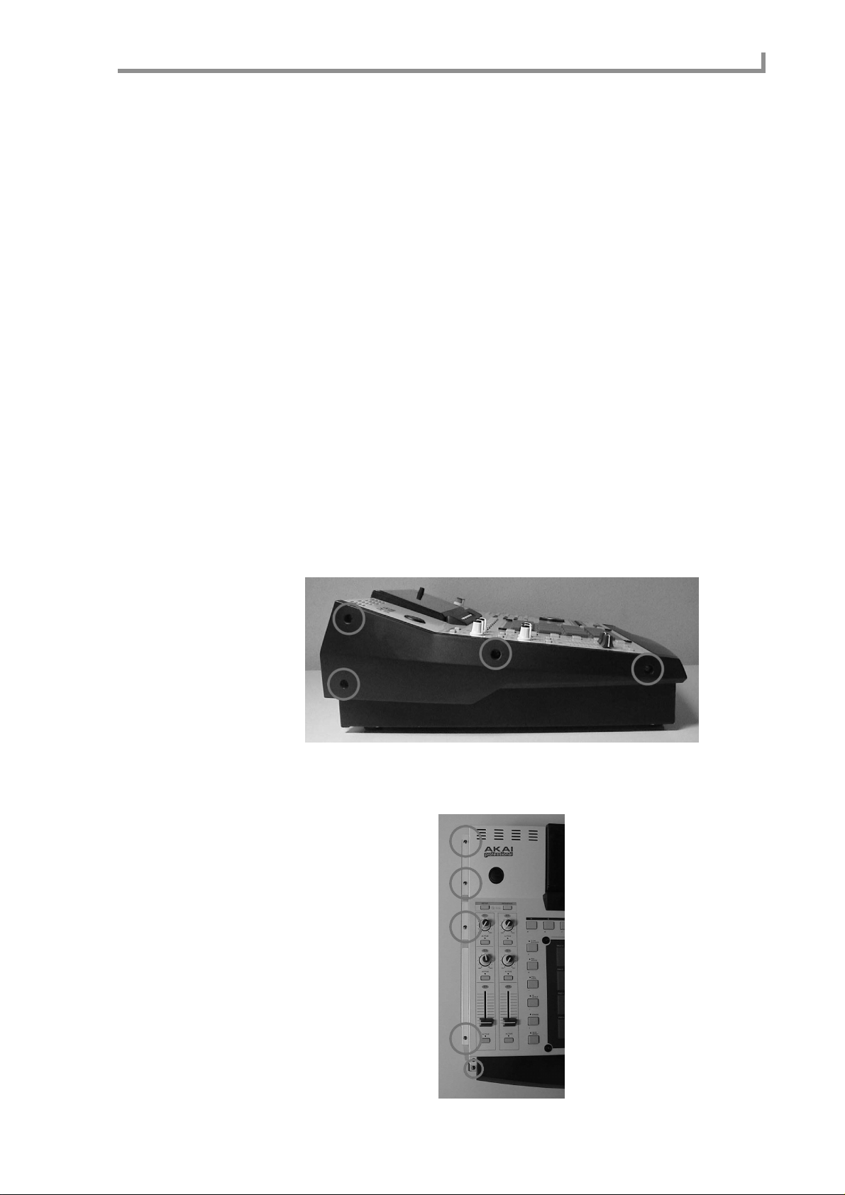
2. Remove the screws (five on each side, left and right) that fasten each side of the
top panel to the chassis.
251
Page 4

Appendix: Installing storage devices (for service engineers)
3. Remove the screw (located in the center of the front panel) that fastens the top
panel from the lower front side.
4. Remove the screw (located in the center of rear panel) that fastens the top
panel from the rear side.
5. Use both hands to lift the protrusion on the front of the top panel, and open the
top panel.
252
Page 5

Installing a drive
6. Use a metal rod or similar object as a prop inside the chassis to hold up the top
panel.
• The side panels and screws you removed must be kept in a safe place.
• T o close the top panel, re-tighten the scre ws in the opposite order to which the y were
removed.
Installing a drive
1. If you are installing a removable-media drive such as a CD-ROM drive or Zip
drive, remove the blank panel from the front panel.
2. Detach the bracket that is attached to the bottom panel of the chassis.
3. Use the hard disk attachment screws (included with the MPC4000) to attach
the drive to the bracket, and re-attach the bracket to the bottom panel of the
chassis.
When installing a drive in the 3.5 inch bay
PC IO
PC IO AD_DA
P7
P8
P2
PC CPU
253
Page 6

Appendix: Installing storage devices (for service engineers)
When installing a drive in the 5 inch bay
Cable connections
Connecting the flat cable
1. Remove two screws from the cover that conceals the PC CPU board.
When you remove the cover, you will see the P2 connector for the ATA drive.
PC IO
PC IO AD_DA
P7
P8
P2
PC CPU
P23
254
PC IO AD_DA
P7
P8
PC IO
P2
PC CPU
Step 1
2. 3Insert the blue connector of the included flat cable into the P2 connector of
the PC CPU board.
3. Reattach the cover that you removed.
4. Connect the other end of the flat cable to the drive.
Page 7

Cable connections
Connecting the power cable
1. Insert the connector of the included power cable into the P7 connector or P8
connector of the PC I/O board.
Use the power cable with the ferrite core if you are installing a hard disk. Use the po wer
cable without a ferrite core if you are installing a Zip drive or CD-ROM drive.
2. Connect the other end of the power cable to the drive.
Connecting the CD-ROM analog audio cable
If the CD-ROM dri ve has an analog audio output connector , connect it to the MPC4000’ s
circuit board as follows.
1. Insert the connector of the included CD-ROM analog audio cable into the P23
connector of the PC I/O ADDA board.
2. Insert the other end of the CD-ROM analog audio cable into the analog audio
output connector of the CD-ROM drive.
Make connections so that the red cable goes to R (right channel) and the white cable to
L (left channel).
3. On the PC I/O ADDA board, plug in the P22 jumper (located in front of P23) at
the “SET” position.
Connecting the CD-ROM digital audio cable
If the IB-4D digital I/O option is installed in the MPC4000, connect the digital audio output connector of the CD-ROM drive to the IB-4D as follows.
1. Insert the connector of the included CD-ROM digital audio cable into the
digital audio output connector of the CD-ROM drive.
Make connections so that the black cable is the ground.
2. Insert the other end of the CD-ROM digital audio cable into the P1 connector
of the IB-4D digital I/O option.
3. On the IB-4D circuit board, plug in the JP1 jumper in the 1-2 (SHORT) position.
* If you connect the analog/digital audio cable and make the correct jumper setting, you
will be able to select the CD-ROM playback as the recording source in RECORD mode.
Master/slave settings for ATA drives
If you install two drives, you must set one as the master and the other as the slave. (If a
hard disk is installed, set the hard disk as the master.)
For details on how to make master/sla ve settings, refer to the manual that came with your
drive.
255
Page 8

Page 9

 Loading...