

Page 1
mpc2000xl
MIDI PRODUCTION CENTER
WARNING
To prevent fire or shock hazard, do not
expose this appliance to rain or moisture.
Operator's Manual
Page 2
WARNING!!
To prevent fire or shock hazard, do not expose this appliance to rain or moisture.
CAUTION
RISK OF ELECTRIC SHOCK
DO NOT OPEN
1-En
5 / 10 / 1999
CAUTION: TO REDUCE THE RISK OF ELECTRIC SHOCK
DO NOT REMOVE COVER (OR BACK).
NO USER-SERVICEABLE PARTS INSIDE.
REFER SERVICING TO QUALIFIED SERVICE PERSONNEL.
THE SYMBOLS ARE RULED BY UL STANDARDS (U.S.A.)
The lightning flash with arrowhead symbol , within an equilateral triangle, is
intended to alert the user to the presence of uninsulated “dangerous voltage”
within the product’s enclosure; that may be of sufficient magnitude to
constitute a risk of electric shock to persons.
The exclamation point within an equilateral triangle is intented to alert the user
to the presence of important operating and maintenance (servicing) instructions in the literature accompanying the appliance.
5B-En
Page 3

Warning
WARNING: WHEN USING ELECTRIC PRODUCTS, BASIC PRECAUTIONS SHOULD
ALWAYS BE FOLLOWED, INCLUDING THE FOLLOWING:
WARNING
The MPC2000XL is designed to be used in a standard household environment.
Power requirements for electrical equipment vary from area to area. Please ensure that
your MPC2000XL meets the power requirements in your area. If in doubt, consult a qualified
electrician or Akai Professional dealer.
120 VAC @ 60 Hz for USA and Canada
220~240 VAC @ 50 Hz for Europe
PROTECTING YOURSELF AND THE MPC2000XL
• Never touch the AC plug with wet hands.
• Always disconnect the MPC2000XL from the power supply by pulling on the plug, not the
cord.
• Allow only an Akai Professional dealer or qualified professional engineer to repair or
reassemble the MPC2000XL. Apart from voiding the warranty, unauthorized engineers
might touch live internal parts and receive a serious electrical shock. There are no
serviceable parts inside.
• Do not put, or allow anyone to put any object, especially metal objects, into the
MPC2000XL.
• Use only a household AC power supply. Never use a DC power supply.
• If water or any other liquid is spilled into or onto the MPC2000XL, disconnect the power,
and call your dealer.
• Make sure that the unit is well-ventilated, and away from direct sunlight.
• To avoid damage to internal circuitry, as well as the external finish, keep the MPC2000XL
away from sources of direct heat (stoves, radiators, etc.).
• Avoid using aerosol insecticides, etc. near the MPC2000XL. They may damage the
surface, and may ignite.
• Do not use denaturated alcohol, thinner or similar chemicals to clean the MPC2000XL.
They will damage the finish.
• Modification of this equipment is dangerous, and can result in the functions of the
MPC2000XL being impaired. Never attempt to modify the equipment in any way.
• Make sure that the MPC2000XL is always well-supported when in use (either in a
specially-designed equipment rack, or a firm level surface).
• In order to assure optimum performance of your MPC2000XL, select the setup location
carefully, and make sure the equipment is used properly. Avoid setting up the
MPC2000XL in the following locations:
1. In a humid or dusty environment
2. In a room with poor ventilation
3. On a surface which is not horizontal
4. Inside a vehicle such as a car, where it will be subject to vibration
5. In an extremely hot or cold environment
Page i
Page 4

Warning
WARNING
THIS APPARATUS MUST BE EARTHED
IMPORTANT
This equipment is fitted with an approved non-rewireable UK mains plug.
To change the fuse in this type of plug proceed as follows:
1) Remove the fuse cover and old fuse.
2) Fit a new fuse which should be a BS1362 5 Amp A.S.T.A or BSI approved type.
3) Refit the fuse cover.
If the AC mains plug fitted to the lead supplied with this equipment is not suitable for your type of
AC outlet sockets, it should be changed to an AC mains lead, complete with moulded plug, to the
appropriate type. If this is not possible, the plug should be cut off and a correct one fitted to suit
the AC outlet. This should be fused at 5 Amps.
If a plug without a fuse is used, the fuse at the distribution board should NOT BE GREATER than 5
Amp.
PLEASE NOTE: THE SEVERED PLUG MUST BE DESTROYED TO AVOID A POSSIBLE
SHOCK HAZARD SHOULD IT BE INSERTED INTO A 13 AMP SOCKET
ELSEWHERE.
The wires in this mains lead are coloured in accordance with the following code:
GREEN and YELLOW —EARTH
BLUE —NEUTRAL
BROWN —LIVE
As the colours of the wires in the mains lead of this apparatus may not correspond with the
coloured markings identifying the terminals in your plug, please proceed as follows:
The wire which is coloured GREEN and YELLOW must be connected to the terminal which is
marked with the letter E or with the safety earth symbol
GREEN and YELLOW.
The wire which is coloured BLUE must be connected to the terminal which is marked with the
letter N or coloured BLACK.
The wire which is coloured BROWN must be connected to the terminal which is marked with
the letter L or coloured RED.
THIS APPARATUS MUST BE EARTHED
Ensure that all the terminals are securely tightened and no loose strands of wire exist.
Before replacing the plug cover, make certain the cord grip is clamped over the outer sheath of
the lead and not simply over the wires.
or coloured GREEN or coloured
6D-En
Page ii
Page 5
Warning
FCC WARNING
This equipment has been tested and found to comply with the limits for a Class B digital device pursuant
to Part 15 of the FCC rules. These limits are designed to provide reasonable protection against harmful
interference in a residential installation. This equipment generates, uses, and can radiate radio
frequency energy and, if not installed and used in accordance with the instructions, may cause harmful
interference to radio communications. However, there is no guarantee that interference will not occur
in a particular installation. If this equipment does cause harmful interference to radio or television
reception, which can be determined by turning the equipment off and on, the user is encouraged to try
to correct the interference by one or more of the following measures:
• Reorient or relocate the receiving antenna.
• Increase the separation between the equipment and receiver.
• Connect the equipment into an outlet on a circuit different from that to which the receiver is
connected.
• Consult the dealer or an experienced radio/TV technician for help.
21B-En
AVIS POUR LES ACHETEURS CANADIENS DU AMX10
Le présent appareil numérique n’ément pas de bruits radioélectriques dépassant les limites applicables
aux appareils numériques de la Class B prescrites dans le Règlement sur le brouillage radioélectrique
édicté par le ministère des Communications du Canada.
27-F
This digital apparatus does not exceed the Class B limits for radio noise emissions from digital apparatus
set out in the Radio Interference Regulations of the Canadian Department of Communications.
27-En
VENTILATION
Do not prevent the unit's ventilation, especially by placing the unit on the soft carpet, in a narrow space,
or by placing objects on the unit's chassis—top, side, or rear panels. Always keep the unit's chassis
at least 10 centimeters from any other objects.
31C-En
CHANGES OR MODIFICATIONS NOT EXPRESSLY APPROYED BY THE MANUFACTURER FOR
COMPLIANCE COULD VOID THE USER’S AUTHORITY TO OPERATE THE EQUIPMENT.
32-En
COPYRIGHT NOTICE
The AKAI MPC2000XL is a computer-based device, and as such contains and uses software in
DISKs and ROMs. This software, and all related documentation, including this Operator’s Manual,
contain proprietary information which is protected by copyright laws. All rights are reserved. No part
of the software or its documentation may be copied, transferred or modified. You may not modify,
adapt, translate, lease, distribute, resell for profit or create derivative works based on the software
and its related documentation or any part there of without prior written consent from AKAI Electric
Co. Ltd, Yokohama, Japan.
Page iii
Page 6

Warranty
WARRANTY
AKAI Electric Co. Ltd. warrants its products, when purchased from an authorized “AKAI professional” dealer, to be free from defects in materials and workmanship for a period of 12 (twelve)
months from the date of purchase. Warranty service is effective and available to the original
purchase only, and only on completion and return of the AKAI Warranty Registration Card within 14
days of purchase.
Warranty coverage is valid for factory-authorized updates to AKAI instruments and their software,
when their installation is performed by an authorized AKAI Service Center, and a properly completed
Warranty Registration has been returned to your “AKAI professional” dealer.
To obtain service under this warranty, the product must, on discovery of the detect, be properly packed
and shipped to the nearest AKAI Service Center. The party requesting warranty service must provide
proof of original ownership and date of purchase of the product.
If the warranty is valid, AKAI will, without charge for parts or labor, either repair or replace the
defective part(s). Without a valid warranty, the entire cost of the repair (parts and labor) is the
responsibility of the product's owner.
AKAI warrants that it will make all necessary adjustments, repairs and replacements at no cost to
the original owner within 12 (twelve) months of the purchase date if:
1) The product fails to perform its specified functions due to failure of one or more of its
components.
2) The product fails to perform its specified functions due to defects in workmanship.
3) The product has been maintained and operated by the owner in strict accordance with the
written instructions for proper maintenance and use as specified in this Operator's Manual.
Before purchase and use, owners should determine the suitability of the product for their intended
use, and owner assumes all risk and liability whatsoever in connection therewith. AKAI shall not be
liable for any injury, loss or damage, direct or consequential, arising out of use, or inability to use
the product.
The warranty provides only those benefits specified, and does not cover defects or repairs needed
as a result of acts beyond the control of AKAI, including but not limited to:
1) Damage caused by abuse, accident, negligence. AKAI will not cover under warranty any
original factory disk damaged or destroyed as a result of the owner's mishandling.
2) Damage caused by any tampering, alteration or modification of the product: operating
software, mechanical or electronic components.
3) Damage caused by failure to maintain and operate the product in strict accordance with the
written instructions for proper maintenance and use as specified in this Operator's Manual.
4) Damage caused by repairs or attempted repairs by unauthorized persons.
5) Damage caused by fire, smoke, falling objects, water or other liquids, or natural events
such as rain, floods, earthquakes, lightning, tornadoes, storms, etc.
6) Damage caused by operation on improper voltages.
IMPORTANT NOTE: This warranty becomes void if the product or its software is
electronically modified, altered or tampered with in any way.
AKAI shall not be liable for costs involved in packing or preparing the product for shipping, with regard
to time, labor, or materials, shipping or freight costs, or time or expense involved in transporting the
product to and from AKAI Authorized Service Center or Authorized Dealer.
AKAI will not cover under warranty an apparent malfunction that is determined to be user error, or
owner's inability to use the product.
THE DURATION OF ANY OTHER WARRANTIES, WHETHER IMPLIED OR EXPRESS, INCLUDING BUT NOT LIMITED TO THE IMPLIED CONDITION OF MERCHANTABILITY, IS LIMITED TO
THE DURATION OF THE EXPRESS WARRANTY HEREIN.
AKAI hereby excludes incidental or consequential damages, including but not limited to:
1) Loss of time.
2) Inconvenience
3) Delay in performance of the Warranty.
4) The loss of use of the product.
5) Commercial loss.
6) Breach of any express or implied warranty, including the Implied Warranty of Merchantability, applicable to this product.
Page iv
Page 7

Contents
Table of Contents
Chapter 1: Introduction ............................................................................................... 1
Features .............................................................................................................. 2
Panel Descriptions............................................................................................... 4
Front Panel.............................................................................................. 4
Rear Panel .............................................................................................. 7
Handling Floppy Disks......................................................................................... 8
The Disk Drive......................................................................................... 8
Taking care of your Disks........................................................................ 8
CD-ROM Care......................................................................................... 9
Chapter 2: The Basics ............................................................................................... 10
Hooking Up Your System .................................................................................. 11
The Terms Used in MPC2000XL....................................................................... 12
Sequence .................................................................................. 12
Track ......................................................................................... 12
Song.......................................................................................... 12
Sound........................................................................................ 13
Drum Pads ................................................................................ 13
Note Number............................................................................. 13
Program .................................................................................... 13
Operating the Front Panel and Screen.............................................................. 14
The Cursor, Cursor Keys, Data Fields ...................................... 15
The Numeric Keypad and DATA Wheel.................................... 15
The Function Keys .................................................................... 15
Basic Functions ................................................................................................. 16
Loading and Playing Programs ............................................................. 16
Playing the Drum Pads, the PAD BANK, & FULL LEVEL Keys ............ 18
Selecting Programs ............................................................................... 19
The NOTE VARIATION Slider, ASSIGN and AFTER keys................... 19
The ASSIGN Key ...................................................................... 20
The AFTER key......................................................................... 21
The 16 LEVELS key .............................................................................. 22
Chapter 3: Recording Sequences............................................................................. 24
How Sequences are Organized......................................................................... 24
Bar.Beat.Tick............................................................................. 25
Examples of Sequence Recordings .................................................................. 26
Example 1: Recording a Drum Pad Performance ..................... 26
Example 2: Recording a Loop................................................... 28
Example 3: Recording With External MIDI Equipment.............. 30
The MAIN SCREEN .......................................................................................... 32
Selecting a Sequence ........................................................................... 32
Renaming a Sequence.............................................................. 32
Name Window........................................................................... 33
Deleting a Sequence................................................................. 33
Copying a Sequence................................................................. 34
Next sequence function............................................................. 34
Second Sequence Feature ....................................................... 36
Page v
Page 8

Contents
Setting the Tempo ................................................................................. 37
Tempo Change Window............................................................ 37
Entering and Modifying a Tempo Change................................. 38
Selecting a Tempo Source .................................................................... 39
Setting the Time Correct (Quantization)................................................ 40
Setting the Beat..................................................................................... 41
Setting the Number of Bars ................................................................... 42
Looping a Sequence ............................................................................. 44
Setting the Recording Count In/Metronome .......................................... 45
Selecting a Track................................................................................... 47
Renaming a Track..................................................................... 47
Deleting a Track ........................................................................ 48
Copying a Track ........................................................................ 48
Turning the Track ON or OFF ............................................................... 49
Deleting All the Tracks that You Have Turned Off ................................ 50
Setting the Track Type .......................................................................... 50
Settings for MIDI Reception .................................................................. 51
MIDI Filter Function ............................................................................... 52
Setting the Track’s MIDI Channel.......................................................... 52
Settings for MIDI Output........................................................................ 53
Multiple Track Recording....................................................................... 54
Editing the Velocity................................................................................ 55
Setting the Program Change Transfer .................................................. 56
Locating with the DATA Wheel.............................................................. 56
Units Used to Locate a Point..................................................... 56
The Main Screen Function Keys ........................................................... 57
The Play/Record Keys and the Locate Keys ..................................................... 58
The AUTO PUNCH IN/OUT Function................................................................ 60
Chapter 4: Editing Sequences .................................................................................. 61
Overview............................................................................................................ 62
Erasing Data with the ERASE Key .................................................................... 62
Erasing a Note in Real Time ..................................................... 62
Using the ERASE Window to Erase Data ................................. 62
Step Editing ....................................................................................................... 64
Step Editing Screen............................................................................... 64
Timing Correct in Step Edit ....................................................... 65
The Event Display ..................................................................... 65
Operating the List Display ......................................................... 66
Selecting and Editing Multiple Events ....................................... 66
Copying an Event...................................................................... 67
Deleting an Event...................................................................... 67
Pasting an Event ....................................................................... 67
Inserting an Event ..................................................................... 68
Step Recording...................................................................................... 68
The Editing Screen ............................................................................................ 69
Copying an Event...................................................................... 69
Editing the Duration of a Note ................................................... 70
Editing the Velocity of a Note .................................................... 70
Transposing a Note................................................................... 71
Copying by Bar.......................................................................... 72
Rearranging the tracks.............................................................. 73
Page vi
Page 9

Contents
Sequence Preferences.............................................................. 74
Transposing a Track ................................................................. 74
Chapter 5: Song Mode ............................................................................................... 76
Overview............................................................................................................ 76
Song Mode ........................................................................................................ 78
Creating a Song .................................................................................... 78
Renaming a Song.................................................................................. 79
Selecting a Song ................................................................................... 78
Deleting a Song..................................................................................... 80
Copying a Song..................................................................................... 81
Setting the Tempo ................................................................................. 82
Setting the Loop .................................................................................... 83
Selecting a Step and Changing a Sequence......................................... 84
Repeating a Sequence.......................................................................... 84
Deleting a Step...................................................................................... 85
Inserting a Step ..................................................................................... 85
Moving to a Specific Point in a Song (Locate)....................................... 86
Converting a Song to a Sequence ........................................................ 87
Chapter 6: Creating and Editing Sounds ................................................................. 88
Sampling a New Sound ..................................................................................... 89
Editing a Sound ................................................................................................. 93
Selecting a Sound ................................................................................. 93
Renaming or Displaying the Specification of the Sound ........... 93
Deleting a Sound....................................................................... 94
Copying a Sound....................................................................... 94
Converting a Sound............................................................................... 95
Converting Stereo to Mono ....................................................... 95
Converting Mono to Stereo ....................................................... 96
Re-sampling .............................................................................. 97
TRIM Mode............................................................................................ 98
Fine Adjustment of the Start Point ............................................ 99
Fine Adjustment of the End Point............................................ 100
LOOP Mode ........................................................................................ 101
Fine Adjustment of the Loop Points ........................................ 102
ZONE Mode ........................................................................................ 103
Fine Adjustment of the Start Point of a Zone .......................... 103
Fine Adjustment of the End Point of a Zone ........................... 104
EDIT Mode .......................................................................................... 104
BPM Match.......................................................................................... 107
Setting the Sound Parameters ............................................................ 109
Beat Loop Function ................................................................. 109
Chapter 7: Creating and Editing Programs ........................................................... 110
What Are Programs? ....................................................................................... 111
Creating a program ............................................................................. 112
Selecting a Program and Assigning a Sound .................................................. 113
Selecting Programs ............................................................................. 113
Renaming Programs ............................................................... 114
Deleting a Program ................................................................. 114
Creating New Programs.......................................................... 115
Page vii
Page 10

Contents
Copying Programs .................................................................. 115
Assigning Notes to the Drum Pads ..................................................... 116
Assigning Sounds to Notes ................................................................. 117
Auto Chromatic Assignement.............................................................. 117
The Pad Assign Mode and Initialize .................................................... 118
Deleting Unused Sounds from the Memory ........................................ 118
The Program Sound Generation Mode ............................................... 119
Editing Note Parameters ................................................................................. 121
Selecting Programs ............................................................................. 121
Selecting Notes ................................................................................... 121
Copying the Note Parameter................................................... 122
Setting the Envelope ........................................................................... 122
Setting the Filter .................................................................................. 124
Setting the Pitch .................................................................................. 125
Setting the Voice Overlap.................................................................... 126
The MIDI Settings of the Sampler ....................................................... 127
Chapter 8: Mixer Functions..................................................................................... 128
Stereo Output Mixer ........................................................................................ 129
Setting the Volume .............................................................................. 129
Setting the Left/Right Pan ................................................................... 130
Linking the Volume/Pan Levels ........................................................... 130
Setting the Individual Outputs and Effect Send (Option) ................................. 131
Assigning the Sounds to Individual Outputs........................................ 131
Setting the Output Level...................................................................... 132
Linking the Individual Outputs/Output Levels ...................................... 132
Sending Effects ............................................................................................... 133
Setting the Effect Send Level .............................................................. 133
Setting the Volume or Pan for Each Note........................................................ 134
Setting Up the Mixer ........................................................................................ 135
Chapter 9: Effects (optional) ................................................................................... 137
Editing Effects.................................................................................................. 138
Turning Each Effect On or Off ......................................................................... 138
Multi-effects ..................................................................................................... 139
Setting the Effect Routing................................................................................ 139
Reverb Effects ................................................................................................. 141
Editing Each Effect ..........................................................................................143
Chapter 10: Disk Operation..................................................................................... 151
Overview.......................................................................................................... 152
The Device: Field ................................................................................ 152
The Device Icons................................................................................. 152
Before Proceeding to Use a Floppy Disk ............................................ 153
Formatting a Disk ............................................................................................ 154
Formatting a Floppy Disk .................................................................... 154
Formatting a SCSI Drive ..................................................................... 155
Saving the Data ............................................................................................... 156
Saving Across Multiple Floppy Disks .................................................. 159
Saving to Folders on a SCSI Device ............................................................... 160
Creating a New Folder ........................................................................ 160
Making Folders Within Folders............................................................ 161
Page viii
Page 11

Contents
Selecting Folders/Files ........................................................................ 162
Deleting Folders .................................................................................. 163
Renaming Folders ............................................................................... 163
Loading Files ................................................................................................... 164
Deleting a File from the Disk ........................................................................... 168
Loading an Updated Operating System .......................................................... 169
Loading Files Created on the AKAI MPC60/60II ............................................. 170
Chapter 11: Flash ROM............................................................................................ 172
Formatting the Flash ROM .............................................................................. 173
Saving to Flash ROM ...................................................................................... 174
Loading From Flash ROM ............................................................................... 174
Deleting Data from Flash ROM ....................................................................... 175
Flash ROM Fragmentation .............................................................................. 175
Editing a Sound Within Flash ROM ................................................................. 176
Chapter 12: MIDI/SYNC Mode, OTHER Mode ........................................................ 177
MIDI/SYNC Mode ............................................................................................ 178
Synchronizing the MPC2000XL with Other Sequencers..................... 178
Synchronizing Another Sequencer or MTR to the MPC2000XL ......... 180
Synchronizing With SMPTE Time Code.............................................. 182
MIDI Sample Dump ............................................................................. 183
MIDI Footswitch Assignement............................................................. 185
OTHER Mode .................................................................................................. 186
OTHERS Screen ................................................................................. 186
INIT Screen ......................................................................................... 186
VER. Screen........................................................................................ 187
Appendix................................................................................................................... 188
Notes on Using SCSI Drives ........................................................................... 189
Connecting an External SCSI Drive .................................................... 189
SCSI Cables........................................................................................ 189
SCSI ID ............................................................................................... 190
Termination ......................................................................................... 190
Cable Length ....................................................................................... 190
Installing the Options—To Service Technicians .............................................. 191
Location of MPC2000XL Option Boards ................................. 191
Installing Memory Expansion .............................................................. 192
Technical Specifications .................................................................................. 193
The MIDI Implementation Charts..................................................................... 195
Page ix
Page 12

Chapter 1
Introduction
Page 13

Chapter 1: Introduction
Features
The following is a summary of some of the advanced features of the MPC2000XL.
General
• Large 248 x 60 dot LCD display with graphics.
• 6 function keys under the LCD display provide various functions on each page.
• Built-in 1.44 megabyte floppy disk drive to store both sequence and sound data.
• By pressing the OPEN WINDOW key at the parameter you want to edit, you are allowed to
make more detailed parameter settings. It is not necessary to switch between different
pages as in the case of conventional devices to make detail settings.
• Built-in SCSI interface for storing data to external hard disk.
Sampler
• 16-bit, 44.1kHz stereo sampling.
• High capacity sound memory: 2 megabytes standard (22 seconds mono or 11 seconds
stereo), expandable to 32 megabytes with SIMM memory.
• Digital sampling input for direct recording from digital sources with IB-M208P (optional)
board.
• 256 sounds (samples) may be held in memory at one time.
• 32 simultaneous playback voices.
• The envelope or filter can be set for each sound.
• Optional multi-effects generator EB16 for versatile effects.
• Sample files may be loaded from Akai S1000 and S3000 disks.
• IB-M208P (optional) enables you to mix and output internal sampler sounds from 8 individual outputs.
• A maximum of 24 programs (sound assignments and sound parameter settings) can be
created.
• A maximum of up to 4 programs can be played simultaneously.
• A selection between polyphonic (multiple sounds are overlaid when the same sound is
played continuously) or mono (the second sound silences the first).
• It is possible to stop the playing of a sound with another sound. This is used to simulate the
open close effect of the hi hat.
• It is possible to copy a part of a sound as a separate sound or paste a sound to a section of
a sound. It is also possible to mute or reverse part of a sound.
• One MIDI note can play three sounds. The sounds can be played simultaneously, switched
by velocity, or with the NOTE VARIATION slider.
• Loop settings can be made to a sound.
• The velocity can change the playback pitch..
• When phrase sampling, it is possible to calculate the tempo of the phrase from the length of
the sound loop.
• Since the sound wave patterns are displayed, it is possible to edit the sound while watching
the wave pattern. It is also possible to zoom the wave pattern.
• Reading and writing of PC compatible .WAV sound files.
• Timestretch, resample, wave pattern edit functions, etc. are available.
Page 2
Page 14

Chapter 1: Introduction
Sequencer
• Loop recording function enables quick recording by looping short phrases.
• Sequencer memory equivalent to 300,000 notes (including note and other data).
The maximum number events in a sequence is equivalent to 50,000 notes.
• 99 sequences may be held in memory at once. Each sequence contains 64 individual
tracks.
• 2 independent MIDI output ports permit 32 simultaneous MIDI output channels.
• 2 mergeable MIDI inputs.
• The optional SMPTE IC chip (IC-M2TC) enable synchronization with SMPTE time codes.
• MTC (MIDI time code), MMC (MIDI machine control) compatible.
• Data can be exported to or imported from standard MIDI files.
• Step edit function enables you to edit individual events.
• The velocity of each track can easily be modified.
• It is possible to record to 32 MIDI channels at one time.
• Tap Tempo feature allows the playback tempo to be set by tapping a key in the time of 1/4notes.
• Programmable tempo changes in mid-sequence or mid-song are supported.
• Auto Punch feature enables you to punch in or punch out automatically in the designated
sequence.
• Swing feature enables you to add a swing-feel to the rhythm.
• 16 velocity- and pressure-sensitive front panel drum pads and 4 pad banks provide a total
of 64 pad/bank combinations.
• Track mute can be turned on or off and sequences can be selected using the drum pads.
• The NOTE VARIATION slider controls the decay or filter value of the sound in real time.
• Since it is possible to convert MIDI sustain pedal data to note duration data, you can place
sustain effects independently from the note data within a track.
• The note repeat function and the after touch function pads enable you to easily enter drum
rolls and hi-hat beats.
• The UNDO SEQ key enables you to undo sequence recordings or edits.
• The 2nd sequence function allows a separate sequence to be played at the same time that
another sequence (or song) is being played/recorded.
Page 3
Page 15
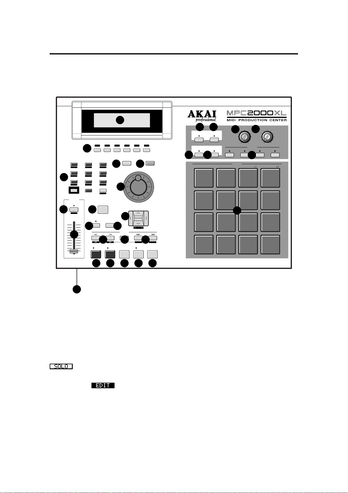
Panel Descriptions
Front Panel
INTEGRATED RHYT HM MACHINE 16 BIT DRUM SAMPLER / MIDI SEQUENCER
1
F 4
F 3
MAIN SCREEN OPEN WINDOW
4 5
6
12
LOCATE
GO TO
OVER
STOP
DUB
2
7
OTHER
MIXER
456
SAMPLE TRIM
3
1
SONG
MISC
SHIFT
NOTE
VARIATION
AFTER
7
ASSIGN
10 11
8
F 1 F 2
F 1 F 2 F 3 F 4 F 5
9
8
MIDI/SYNC
PROGRAM
23
.
LOAD
ENTER
0
SAVE
TAP TEMPO
NOTE REPEAT
9
UNDO SEQ
ERASE
STEP
13 14 15
EVENT
REC
F 5 F 6
F 6
DATA
CURSOR
DIGIT
BAR
START END
PLAY
START
Chapter 3: Recording Sequences
21 22
16 LEVELS
FULL LEVEL
SPACE
A/a
TRACK MUTE
NEXT SEQ
25
PLAY
26
PAD 13
PAD 9 PAD 10
PAD 5
PAD 1 PAD 2 PAD 3 PAD 4
PAD 14
YZ
QR ST
PAD 6 PAD 7
IJ
AB
REC GAIN
23
MIN
A
DRUMS
PAD 15
#
&
PAD 11
KL
28
CD
B
MAX
PAD BANK
27
24
UV
MN
EF
MAIN VOLUME
MAX
MIN
CD
PAD 16
PAD 12
WX
PAD 8
OP
GH
20
1
162917 18 19
LCD
All the function windows are displayed here. This
adjustable display can be tilted to 3 different angles
for clearer viewing.
Function keys
2
These keys execute the function shown on the very
bottom of the display.
Functions surrounded by a rectangular frame
can be executed.
Letters without a surrounding box, indicate the currently selected page.
Reversed display indicates that you can
jump to that page by pressing the corresponding
key.
Numeric keys / Mode keys
3
These allow you to directly enter numeric data.
Enter numbers with these keys into selected numeric fields and press the ENTER key.
If you are entering numbers with a decimal
value, enter the number ignoring the decimal point.
(example: 120.5, enter 1205.)
If you make a mistake, it is possible to cancel by
pressing the SHIFT key before the ENTER key.
If you use the CURSOR keys, DATA wheel, or
MAIN SCREEN key while you are entering data
with the numeric keys, the input will be canceled
and the data returns to the status before entry the
entry was made.
By holding the SHIFT key and pressing one of the
numeric keys, the key functions as a Mode key and
allows you to enter the mode indicated under the
key.
MAIN SCREEN key
4
This allows you to return from any page to the
MAIN screen (initial screen). The MAIN screen is
the basic screen used to record or play back a sequence.
Page 4
Page 16

Chapter 3: Recording Sequences
OPEN WINDOW key
5
When certain fields are selected, pressing this key
opens another window to allow you to set further
data related to that field.
Pressing the key again closes the window.
DATA wheel
6
This allows you to change the numbers or data of
the selected field. The data variably increases the
faster the wheel is turned.
To set the contrast of the LCD, rotate the DATA
wheel while holding down the SHIFT key. This can
be done at any time, regardless of the mode you
are in.
NOTE VARIATION/AFTER key
7
Normally, the NOTE VARIATION slider is used
when the drum pad is played or when the drum pad
performance is recorded to a sequence.
However, by pressing this key, it is possible to use
the NOTE VARIATION slider while the sequence is
playing. This also needs to be on when you are
overdubbing only the NOTE VARIATION slider effect.
NOTE VARIATION slider
8
This enables you to change the parameters of the
preset internal sound source.
Hold down the SHIFT key and press the AFTER
key to display the screen and then change parameters (TUNING, DELAY, ATTACK and FILTER)
with the slider.
TAP TEMPO / NOTE REPEAT key
9
This allows a sequence to play at the tempo set by
hitting the key.
Hold this key and press one of the drum pads to
play to the beat set in the Timing field on the MAIN
screen. For example, if the Timing is set at 1/8, you
can play the hi-hat at an eight beat by holding this
key and pressing the drum pad that is assigned to
the hi-hat.
This button only operates during the play and record
modes.
If you hold down this key and then press SHIFT , the
NOTE REPEAT feature will be locked and you can
release the buttons and just press the drum pad.
Press NOTE REPEAT again to release the lock
mode.
The length that the drum pad is held determines
the note’s velocity.
UNDO SEQ key
mr
When you record and stop a sequence, the indicator above this key will light. It is now possible to
return the sequence back to the original state before recording by pressing this key (the light will go
out). If the key is pressed again, the indicator will
light and the state will return to the condition after
the last recording. This is convenient for comparing
the recording with the previous one, or to undo a
poor recording.
You can only use the UNDO SEQ key when you
are recording or editing a sequence. You cannot
use this key when you are editing a program or
sound. Using the UNDO SEQ is also limited to the
time just after a recording or edit. If you move to
another mode or function screen, the UNDO SEQ
mode will be disabled.
ERASE key
ms
This is used to erase data on the selected track.
By holding this key and pressing the drum pad of
the sound that you want to erase, while dubbing
over a sequence, you can erase the data (as long
as the PAD is pressed). In addition to drum tracks,
you can erase the notes on a track of an external
MIDI device by holding this key and pressing the
note that needs to be erased on the MIDI keyboard.
The ERASE window will appear if you press this
key while a sequence is not playing. This allows
you to erase specific notes or lengths of data.
CURSOR key
mt
This moves the cursor to select the parameter that
you want to edit. The currently selected field is displayed by white figures on a blue background.
To enter large numbers (when using the trim mode,
for example, to edit sounds) press CURSOR LEFT/
RIGHT while holding down the SHIFT key.
STEP < / > key
mu
This locates the sequence point backwards and forwards one step at a time. The step is set in the
Timing field of the MAIN screen. When Timing is
OFF, you can move a step by one clock. HOLD the
GO TO key and press this key to locate the position
of the next/previous event recorded on a track.
GO TO key
mv
This key displays the locate window. Enter the locate point or move the cursor to the memorized locate point and then press GO TO [F5]. To memorize a locate point, pick a point that you want to
memorize and display the Locate window by pressing the GO TO key, then move the cursor to the
number you want to memorize and press the
STORE [F2] to memorize the point.
Page 5
Page 17

Chapter 1: Introduction
BAR << / >> key
mw
This locates the sequence point by bars. Holding
the GO TO key, press this key to locate the start or
end point of the selected sequence.
REC key
mx
While holding this key, press the PLAY key or the
PLAY START key to begin sequence recording. If
there is data on the track, it will be erased by the
new recording.
OVER DUB key
my
While holding this key, press the PLAY key or the
PLAY START key to begin sequence recording.
The new recording is dubbed over the data on the
track, adding to the original data.
STOP key
mz
This stops the playback or recording of a sequence.
PLAY key
m{
This starts the sequence from the current point
(“Now:” on the MAIN screen). It is also possible to
select “Now:” with the CURSOR keys and set the
position for playback/recording with the DATA
wheel.
PLAY START key
nr
This starts the sequence from the beginning.
REC GAIN knob
nu
This adjusts the level of the sound coming from the
RECORD IN jack during a sampling.
MAIN VOLUME knob
nv
This adjusts the volume of the STEREO OUT and
PHONES jacks. However, this does not adjust the
volume of the optional “assignable mix out” outputs.
NEXT SEQ key
nw
Pressing this key will display the NEXT SEQ screen
that allows you to select another sequence to play
directly following the one already selected.
Although the NEXT SEQ function can be used with
the main screen, the NEXT SEQ screen provides a
wider range of convenient functions that can be
used.
TRACK MUTE key
nx
When this key is pressed and the indicator lights,
you can mute tracks by pressing the corresponding
drum pad (pressing the pad again turns the track
back on). Press the TRACK MUTE key again to cancel the mode.
PAD BANK A–D keys
ny
There are four pad banks from A to D and each has
sixteen sounds, so it is possible to use 64 different
sounds by switching banks. The indicator will light
for the currently selected bank.
FULL LEVEL key
ns
When this key is pressed and the light is on, regardless of how hard the drum pad is hit, the sound will
always be generated at full velocity.
Also used to selected upper or lower case letters
when naming sounds, sequences, etc.
16 LEVELS key
nt
This allows you to assign one selected sound to all
16 pads and set and play the sound at 16 parameter levels of velocity, tone, attack, decay, or filter.
Drum pads
nz
These play back sounds (samples, etc.), including
the drum sounds in the memory.
The loudness of the sounds depend on how hard
you hit the pad.
You can assign up to 64 sounds to the 16 drum
pads by using the 4 pad banks A-D.
Floppy disk drive
n{
The floppy disk drive is used to load or save sound
or sequence data. Both 2HD and 2DD floppy disks
can be used.
Page 6
Page 18
Chapter 1: Introduction
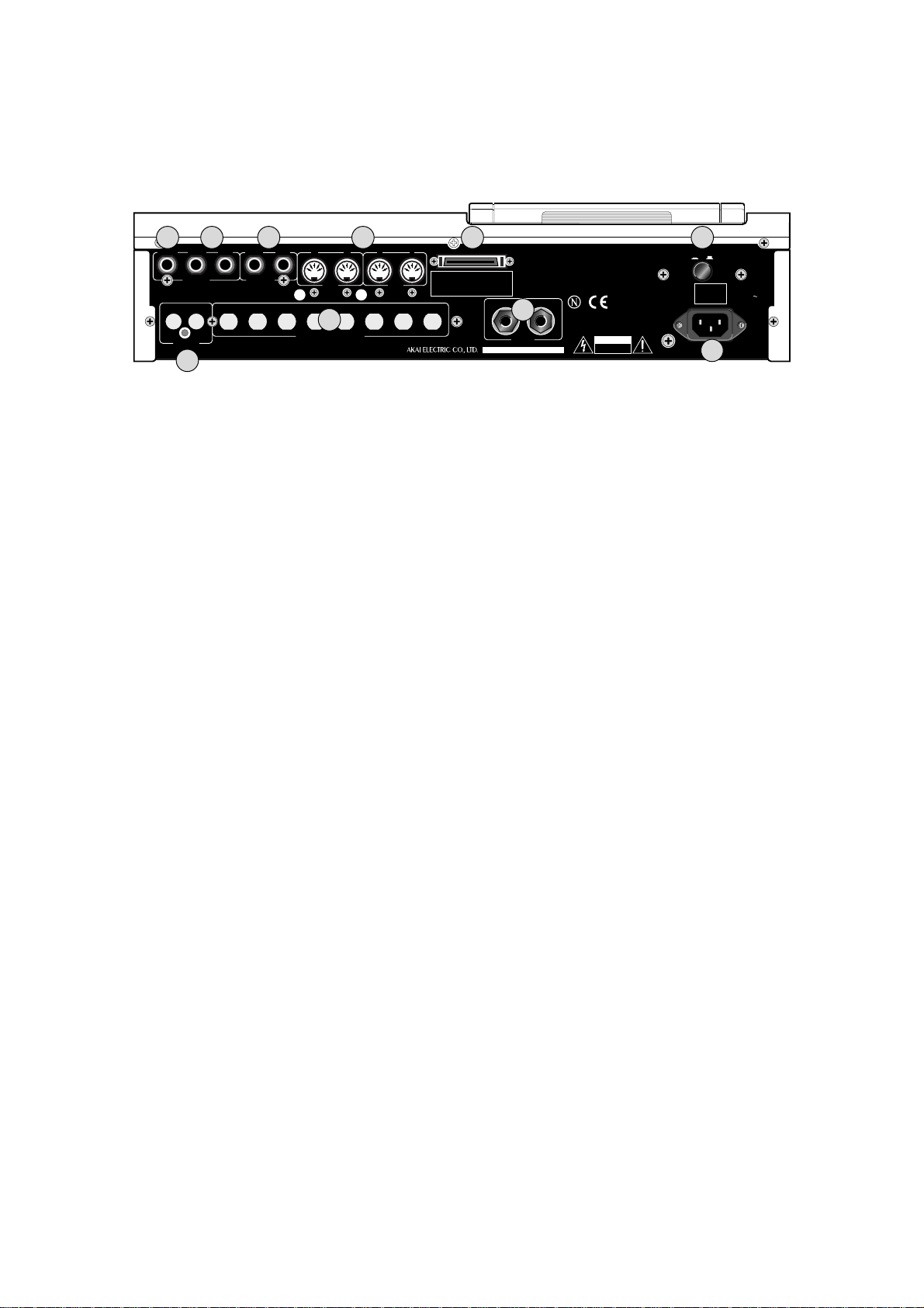
Rear Panel
31 32 33 34 35
30
PHONES
OUT
DIGITAL
RIGHT LEFT
STEREO
OUT
IN
36
RIGHT LEFT
RECORD
IN
AB12
MIDI
OUT
37
ASSIGNABLE MIX OUT
MIDI
SCSI
IN
12345678
WARNING:
SHOCK HAZARD-DO NOT OPEN!
AVIS:
RISQUE DE CHOC ELECTRIQUE-NE PAS OUVRIR!
VORSICHT:
BERUHRUNGSGEFAHR-NICHT OFFNEN!
IN
OUT
38
SMPTE
MODEL NUMBER MPC2000XL
....
CAUTION
RISK OF ELECTRIC SHO C K
DO NOT OPEN
POWER
ON OFF
AKAI E.L
100- 240V
50/ 60Hz
23W
MADE IN CHINA
39
AC100- 240V
50/ 60Hz
23W
STEREO OUT PHONES
or
Connect your stereo headphones here.
The same sound is output to the STEREO OUT
LEFT and RIGHT jacks.
STEREO OUT LEFT/RIGHT
os
These are the main output jacks.
RECORD IN
ot
These are the input jacks used for sampling. These
stereo phone jacks are balanced inputs.
MIDI IN
ou
These receive MIDI signals. MIDI 1 and 2 signals are merged.
MIDI OUT
These send MIDI signals. Since A and B are
independent, it is possible to handle a total of
32 MIDI channels.
SCSI
ov
This is a 50 pin SCSI interface connector that you
can connect to external disk drives for loading and
saving data.
POWER
ow
This is the power ON/OFF switch.
DIGITAL IN/OUT (option)
ox
This allows you to sample data directly from an audio CD or DAT. It is also possible to record the
entire digital data from this output to a hard disk recorder or DAT, such as the AKAI DR16 or DPS12.
ASSIGNABLE MIX OUT (option)
oy
This allows you to set up to 8 separate outputs for
individual sounds. This gives you more control of
the mixing of the sounds, especially when using an
external mixer or effects unit.
SMPTE IN/OUT (option)
oz
If the unit is equipped with the SMPTE option, these
jacks are used to synchronize to a tape that uses
the SMPTE time code.
AC in
o{
Connect the provided power cable here.
Page 7
Page 19
Chapter 1: Introduction
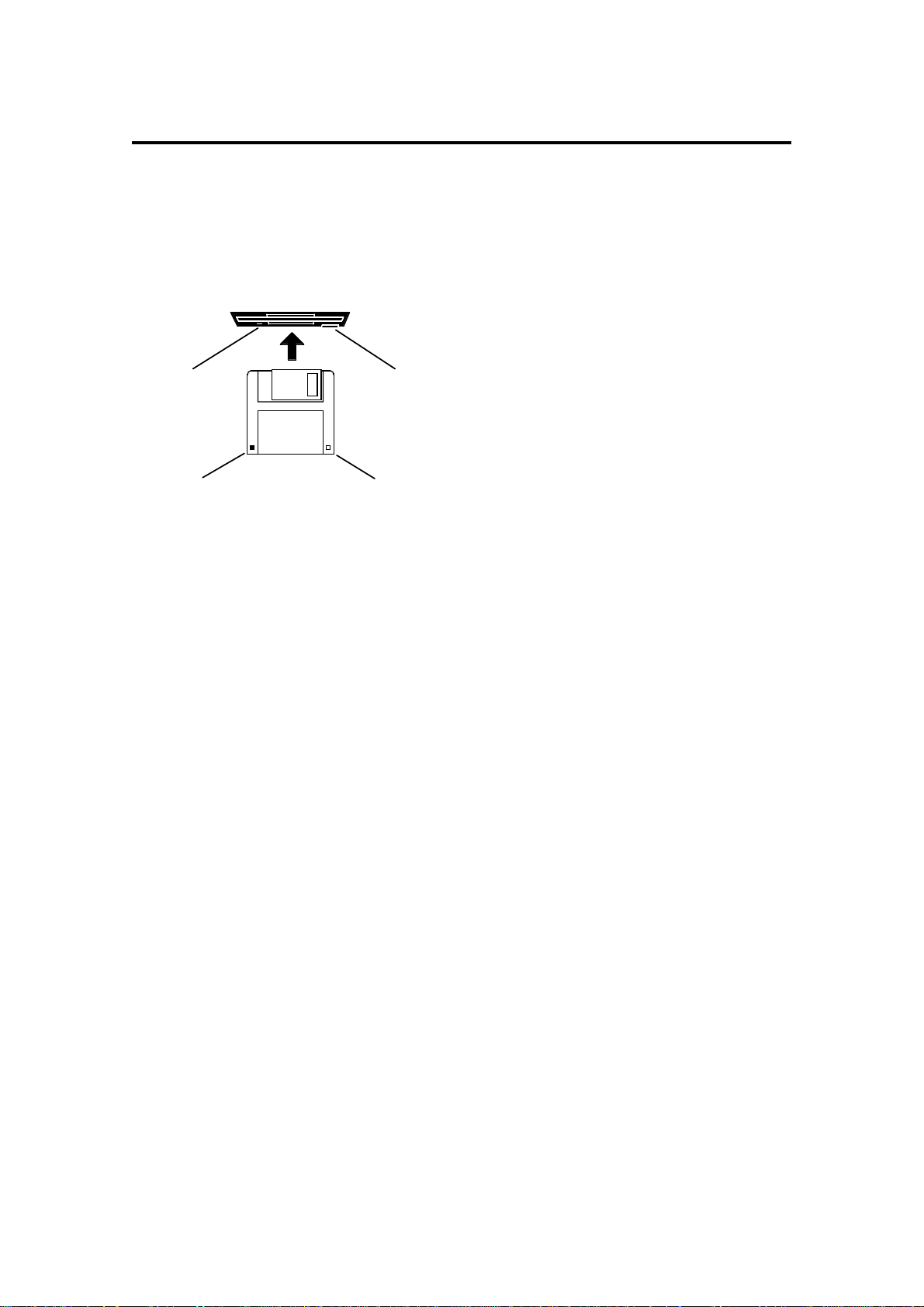
Handling Floppy Disks
The Disk Drive
The 3.5 inch floppy disk drive will accept high density and low density disks.
Disks are inserted into the drive thus:
The label should be facing upwards when it is inserted (actually, it is physically impossible to insert
disks the wrong way round without using an extreme
DISK EJECT BUTTONDISK ACTIVITY LED
WRITE PROTECT TAB
regularly save your work as you are working. All good computer users do this and it prevents the accidental
loss of data should power be accidentally removed from the instrument. This also serves as a form of ‘undo’
- if you make some kind of mistake in your programming and editing and can’t fix it, you can load the last level
of editing back into the unit. It may be a bit tedious to keep stopping every now and then to save your work but
it is better than losing some valuable sounds.
HIGH DENSITY
DETECTION TAB
amount of brute force!).
To eject the disk, simply press the DISK EJECT but-
ton. When a disk is loading, saving or formatting, the
DISK ACTIVITY LED will be lit. Never eject a disk
while the DISK ACTIVITY LED is lit.
As a result, it is vital that you save your work to disk
before turning the power off otherwise you will lose
your work and, unless previously saved or backed
up, it will be gone for ever. In fact, it is a good idea to
Taking care of your Disks
Floppy disks contain valuable sound data and, as such, should be treated with extreme care. Please observe
the following points, therefore:
1. Never slide the metal cover back and touch the disk. Finger marks may render the disk unreadable.
2. Don’t leave the disk in the drive whenever possible. When the disk is in the drive, the metal protective
cover slides back exposing the actual disk inside and this makes the disk susceptible to picking up dust
which may cause read errors.
3. Do not leave your disks in a hot car.
4. Do not place your disks next to any magnetic sources such as speakers, amplifiers, televisions, etc..
Also, try to avoid X-ray machines. At airports, it is sometimes possible to ask for your disks to be inspected by hand at security desks but, with the added security at airports these days, this may not be
possible. Always check with the security officer though, just in case. Security X-ray machines are generally safe with disks, though. If in doubt, make backup copies which should be left at home.
Note: Some checked-in luggage is X-rayed by quite powerful machines that are not as safe as those
that check hand luggage. It is probably best to take your disks as hand luggage.
5. Do not leave your disks around when drinking liquids - one accidental spillage could ruin a lot of work!
6. Always use high quality disks. Whilst cheap ones may be appealing, they are prone to errors more than
good ones.
7. Try to ensure that the write protect tab is switched on (i.e. the tab does not block the hole). This will
prevent accidental erasure, formatting and loss of data. It may be a nuisance to try to write to the disk
and find it write protected but it is less of a nuisance than accidentally over-writing a set of your favourite
samples and programs!
8. Try to get into the habit of labelling your disks - it will pay dividends in the end when you are searching
for something.
9. Invest in a sturdy carrying case for your floppies especially if you are a gigging musician. Heavy duty
metal camera cases are ideal and some flight case manufacturers now make special heavy duty disk
flightcases.
10. Even if you are using a hard disk of any sort, please make sure you have backed up your work to floppy
disks. It can be time consuming but it will be worth it if you ever have a problem with your hard disk!
Page 8
Page 20
Chapter 1: Introduction
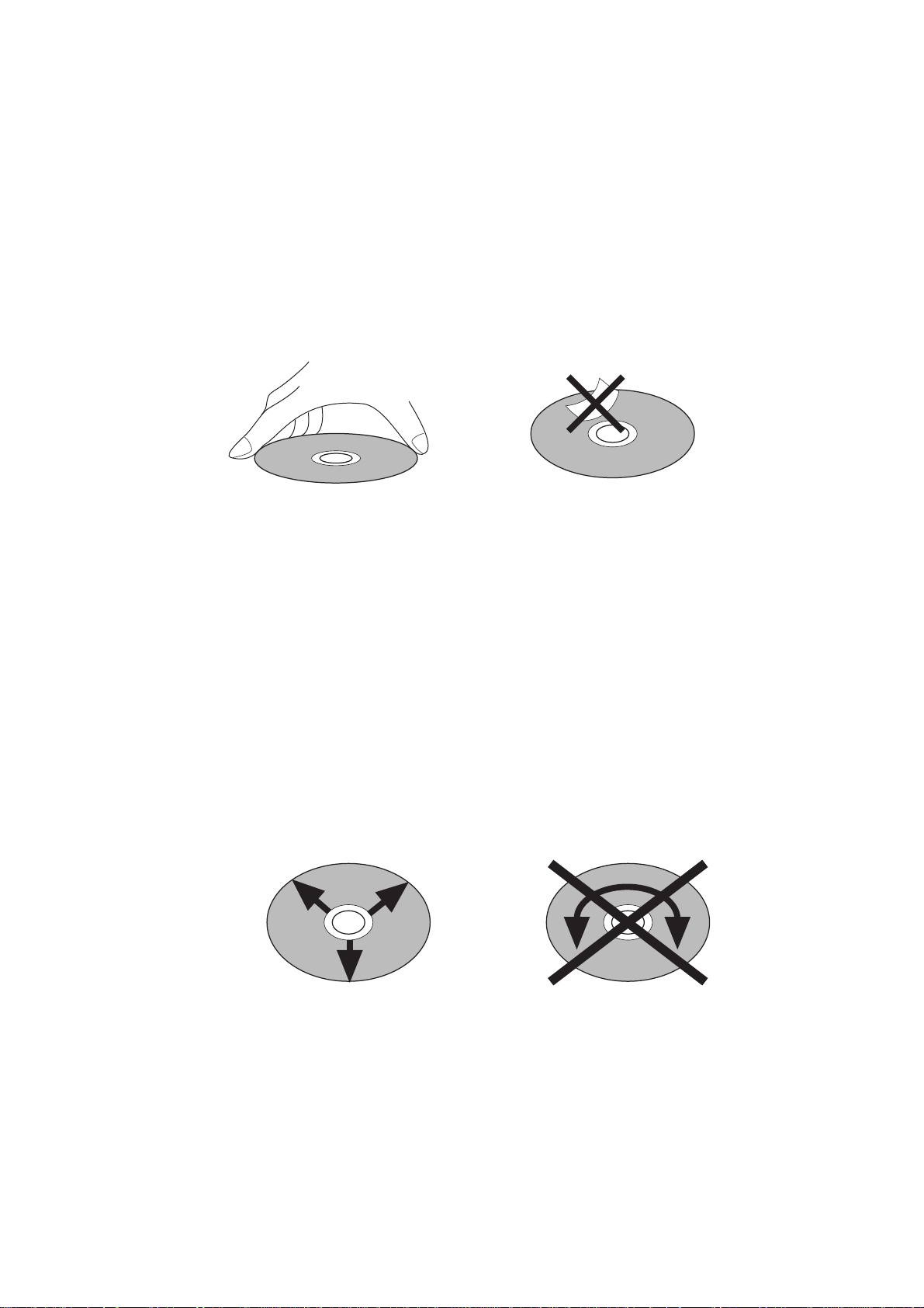
CD-ROM care
Dust, dirt, scratches or warps on the CD-ROM may lead to faulty CD-ROM data loading. In order
to take full advantage of the CD-ROM player’s performance capabilities, follow the precautions
outlined on this page.
Disc handling
Hold the CD-ROM by the outer edge only, supporting it at the center with your index finger if
necessary.
Avoid touching the unprinted side of the disc.
Do not glue any labels or stickers etc., on the disc.
Disc storage
Do not store the CD-ROM in a location which is subject to direct sunlight, high humidity, or hot air
from heating appliances.
Always return the CD-ROM to their plastic cases for storage.
Disc cleaning
It is recommended that you periodically wipe the recorded side of your CD-ROM with a
commercially available silicone cloth (such as that used for cleaning camera lenses or glasses) in
order to remove dust, dirt or fingerprints. Wipe the disc gently, being careful not to scratch its
surface.
When wiping the disc, refer to the illustrations below. Unlike records, CD-ROM should always be
wiped in a straight line from the center to the edge.
Do not use volatile chemical substances such as denatured alcohol, cleaning fluid intended for
analog records, or antistatic fluids, as these may damage the CD-ROM.
Page 9
Page 21

Chapter 2
The Basics
Chapter 2: The Basics
Page 10
Page 22
Chapter 2: The Basics
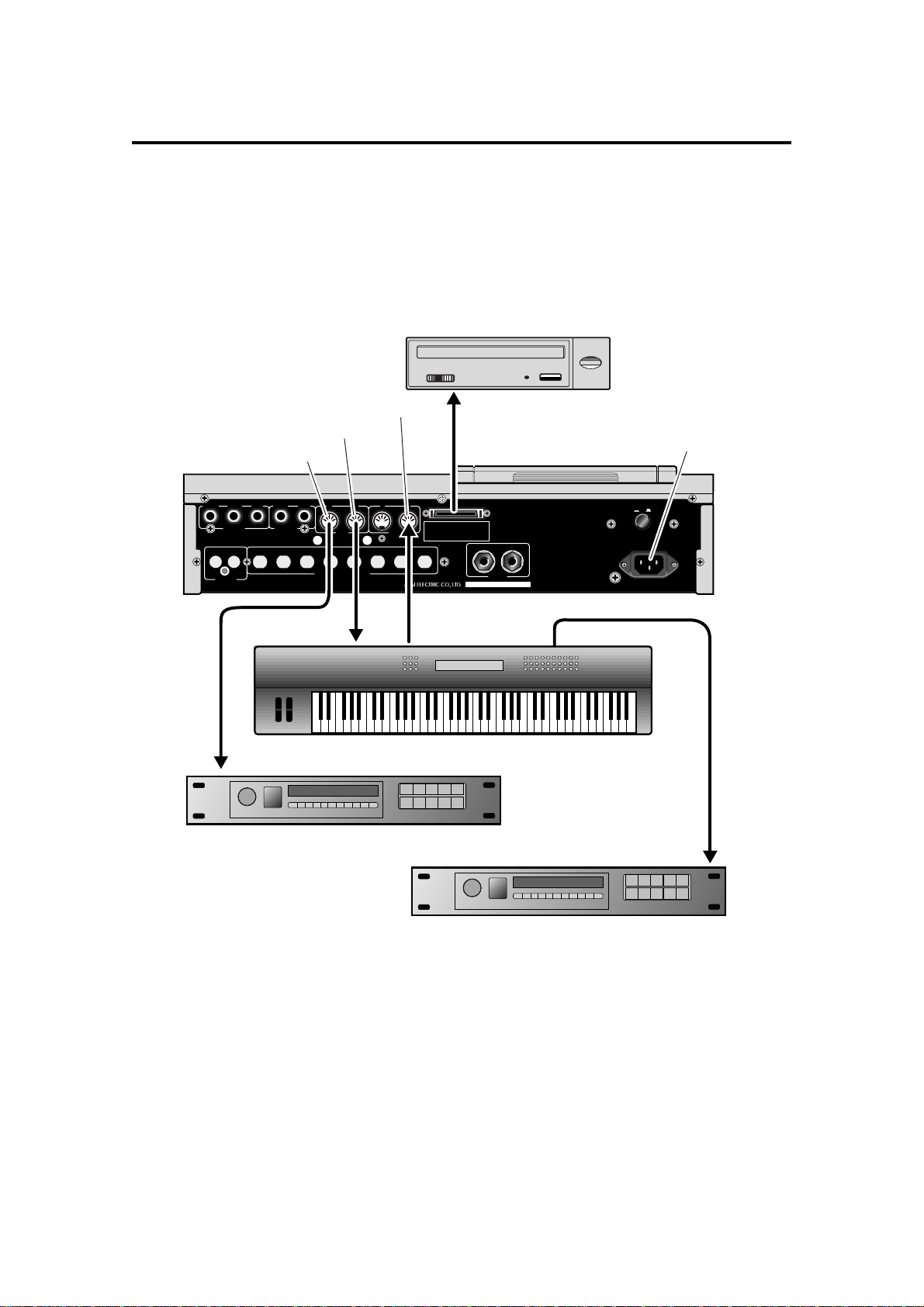
Hooking Up Your System
The following diagram shows how to hook up the MPC2000XL to a MIDI keyboard, two sound
modules and a CD ROM.
You can connect other external SCSI devices (such as a hard disk, ZIP drive, etc.) to the SCSI
interface on the rear panel so that you can save or load samples, songs, etc.
CD ROM player
MIDI IN 1 or 2
MIDI OUT A
MIDI OUT B
Connect power cord and
plug into power supply
RIGHT LEFT
RIGHT LEFT
PHONES
STEREO
OUT
DIGITAL
RECORD
OUT
IN
IN
MIDI
OUT
ASSIGNABLE MIX OUT
MIDI IN
Multi timbral MIDI sound module
12345678
SCSI
OUT
MODEL NUMBER MPC2000XL
SMPTE
AB12
MIDI
IN
MIDI OUT
Multi timbral MIDI keyboard
Multi timbral MIDI sound module
POWER
ON OFF
IN
MIDI THRUMIDI IN
MIDI IN
If you only want to use the MPC2000XL as a drum machine for now, don’t connect the MIDI keyboard,
the sound modules, or make any MIDI connections. If you choose to connect an external MIDI
device, connect the MIDI Output of the MIDI keyboard to MIDI Input of the MPC2000XL, and the MIDI
Input of the MIDI sound source to MIDI Output of the MPC2000XL. MIDI Output provides an A or B
Output. Normally use Output A when there is only one sound source. If you want to use a sound
source from the connected MIDI keyboard, connect the MIDI keyboard MIDI Input to the
MPC2000XL MIDI Output. (In this case, it is necessary to turn the Soft thru function on the
MPC2000XL off. For details, refer to “Setting the Track’s MIDI Channel” on page 52.) To connect
multiple sound sources, use the MIDI THRU jacks of the MIDI device. Connect the MIDI Output of the
MPC2000XL to the MIDI Input of the first MIDI sound source. Connect the MIDI THRU of the first
MIDI sound source to the second MIDI sound source, and so on. MIDI can handle up to 16 data
channels, the MPC2000XL has MIDI Output A and B each with 16 channels enabling you to handle
32 channels of data.
Page 11
Page 23
Chapter 2: The Basics
The Terms Used in MPC2000XL
Here are some definitions of terms used in the MPC2000XL that you should know:
Sequence
A sequence is the most basic unit in creating data on the MPC2000XL. The performance data
from a MIDI keyboard or pad is recorded on each track within a sequence. Each sequence has 64
tracks, to which performance data can be recorded. It is possible to create up to 99 sequences.
Sequence
Track 01
Track 02
Track 03
Piano
Bass
Organ
Track 64
Although data equivalent to a maximum total of 300,000 notes can be recorded on the
MPC2000XL, the number of notes that can be recorded within one sequence is limited to a maximum 50,000 notes.
Note:
It is not possible to Load/save sequence data that exceeds the 50,000 note limit.
(Unused)
When a sequence file that exceeds 50,000 notes is stored on the MPC2000 using the
ALL mode, only 50,000 notes of data will be read when this file is loaded. In this type of
case, use the MPC 2000 to create a separate sequence of the data that was cut from the
original sequence read into the MPC2000XL, then load this into the MPC2000XL and
connect and play the 2 sequences using the SONG mode.
Track
There are 64 tracks in a sequence to which individual performances can be recorded. For example, track 1 could be the piano, track 2 could be the bass, and track 3 the organ. Normally,
each track is recorded one at a time. It is also possible to record a new track while playing the
recorded tracks. Each track can be turned on or off individually. It is possible to record different
piano solos to track 1 and track 2 and compare the combination with the other tracks. You can
select either a Drum track or MIDI track. The drum track plays the recorded data of the internal
sampler. The MIDI track plays the sound of the external MIDI sound source connected to MIDI
OUT.
Song
This function sequentially plays the data of a sequence. You can set the order or number of times
to play the sequence. This is used to play multiple pieces consecutively, or to complete a song by
arranging the sequence data for each part. In the MPC2000XL there are 20 songs, each having
up to 250 steps. A sequence is assigned to each step to create a song. In doing so, it is also
possible to set each step to repeat a number of times.
Song
Step
1
2
3
4
250
Seq
1
103
1
23
Page 12
Repeats
2
1
2
3
Page 24

Chapter 2: The Basics
Sound
Each individually sampled recording in the MPC2000XL is called a sound. A sound can be recorded or loaded from a disk. The start or end of a sound can be changed or the looping of a
sound can be set on the TRIM page. The sound is assigned to a note number and it is possible to
set the envelope, filter, or pitch. Assign a note number to each pad to play the sound from the
MPC2000XL drum pads.
Drum Pads
Sounds are played by assigning them to a drum pad. It is possible to assign up to 64 sounds by
combining the pads with the pad bank keys(16 pads x 4 pad banks). To play a sound from a pad,
assign a sound to a note number then assign the note number to a pad. Details are described in
the “Creating and Editing Programs” chapter. By playing a pad, it is also possible to send the MIDI
note of the note number assigned to that pad from the MIDI output.
Note Number
This refers to the position (note) of the MIDI note event on the keyboard. For example, the note
number for Middle C on the piano is 60. The lowest key on the piano is A-1 which is note number
21. On a MIDI track, the MIDI keyboard performance data is recorded as a note number. On a
Drum track, the note number is used to play back the sound in the internal sample. If you play the
pads and record to a drum track, the note numbers assigned to the pad will be recorded on the
track. When you play back this track, the sound assigned to the note number is played back.
Program
A program is a collection of sounds assigned to 64 note numbers. It is possible to set the envelope
or filter on each note number individually. It is possible to create 24 programs on the MPC2000XL.
The sound is played back by a pad or MIDI note only when it is assigned to a note number in a
program. By assigning a note number to a pad, the sound assigned to that note number can be
played from a pad. When a sequence is played back, the sound is played with the note data
recorded on the track. (When the snare drum is assigned to note number 50, the snare drum is
reproduced with the timing recorded on note number 50.)
You can instantly switch the program by selecting it in PROGRAM mode. It is also possible to use
the MIDI program change feature to switch programs.
A maximum of up to 4 separate programs can be played simultaneously on the MPC2000XL.
Page 13
Page 25
Chapter 2: The Basics
Operating the Front Panel and Screen
Before you can use the MPC2000XL, you must learn how to use the cursor keys, data fields,
numeric key pad and Function keys.
Turn the power on. After the initial loading screens, the following screen will appear:
Sq:01-(Unused)
.......................................................
™:120.0(SEQ) Timing:1/16 Tsig: 4/ 4Tsig: 4/ 4
Count:OFF Loop: ONLoop: ON Bars: 0Bars: 0
..................................................................................................
Tr:01-(Unused) ON:YES Pgm:OFF
S:DRUM1:OFF New Pgm-A S:DRUM1:OFF New Pgm-A Velo%:100
STEP EDIT Tr -
TrMUTE SOLO Tr +
Now:001.01.00
This is the Main Screen and most playback and recording of sequences is done with this screen
displayed. It is discussed further in the chapter entitled “Recording Sequences.”
If at any time while operating the MPC2000XL you are confused and want to return to this screen,
press MAIN SCREEN.
The Cursor, Cursor Keys, Data Fields
Make sure that the Main Screen is showing. If not, press MAIN SCREEN.
The cursor is displayed as white letters on a blue background. You can move the cursor around
the screen using the four CURSOR keys located on the front panel. These four keys are referred
to as the CURSOR LEFT, CURSOR RIGHT, CURSOR UP and CURSOR DOWN keys in the
manual. Try moving the cursor around the screen, then move it back to the upper left corner.
Notice that the cursor does not move from letter to letter, but lands only in certain locations, usually
to the right of a colon (:). These areas are called data fields and each one controls a specific
parameter. For example, the upper left-most data field is called Sq: (an abbreviation for sequence). To the right of this field is another field containing the name of the selected sequence.
The Numeric Keypad and DATA Wheel
Make sure that the Main screen is displayed. If not, press MAIN SCREEN.
To change the data in a field, move the cursor to the field and use the DATA wheel. By rotating the
DATA wheel one click to the right, the number will increase. By rotating the DATA wheel one click
to the left, the number will decrease. If you continuously rotate the DATA wheel, the numbers will
continuously increase or decrease.
There are fields in the data field where you can enter the numbers directly with the numeric keys.
Move the cursor to the field, enter a new number from the numeric keys, and press ENTER. For
example, to change the tempo to 100.0, follow the steps below:
1. Move the cursor to the : : (Tempo) field.
2. Enter 1000 (ignoring the decimal point) with the numeric keys and press the ENTER key.
Page 14
Page 26
Chapter 2: The Basics
There are also fields that select functions instead of entering numbers. Rotate the DATA wheel to
select these functions. For example, move the cursor to the Timing field. Rotate the DATA wheel
one click at a time and check the display change in the field. After you have finished, turn the field
back to “OFF”.
The Function Keys
Make sure that the Main Screen is showing. If not, press the MAIN SCREEN key.
Immediately below the LCD screen are six keys labeled F1, F2, F3, F4, F5 and F6. The functions
of these keys change from one screen to the next; these functions are always displayed on the
lowest line of the screen. For example, while the Main Screen is showing, the bottom line appears
as:
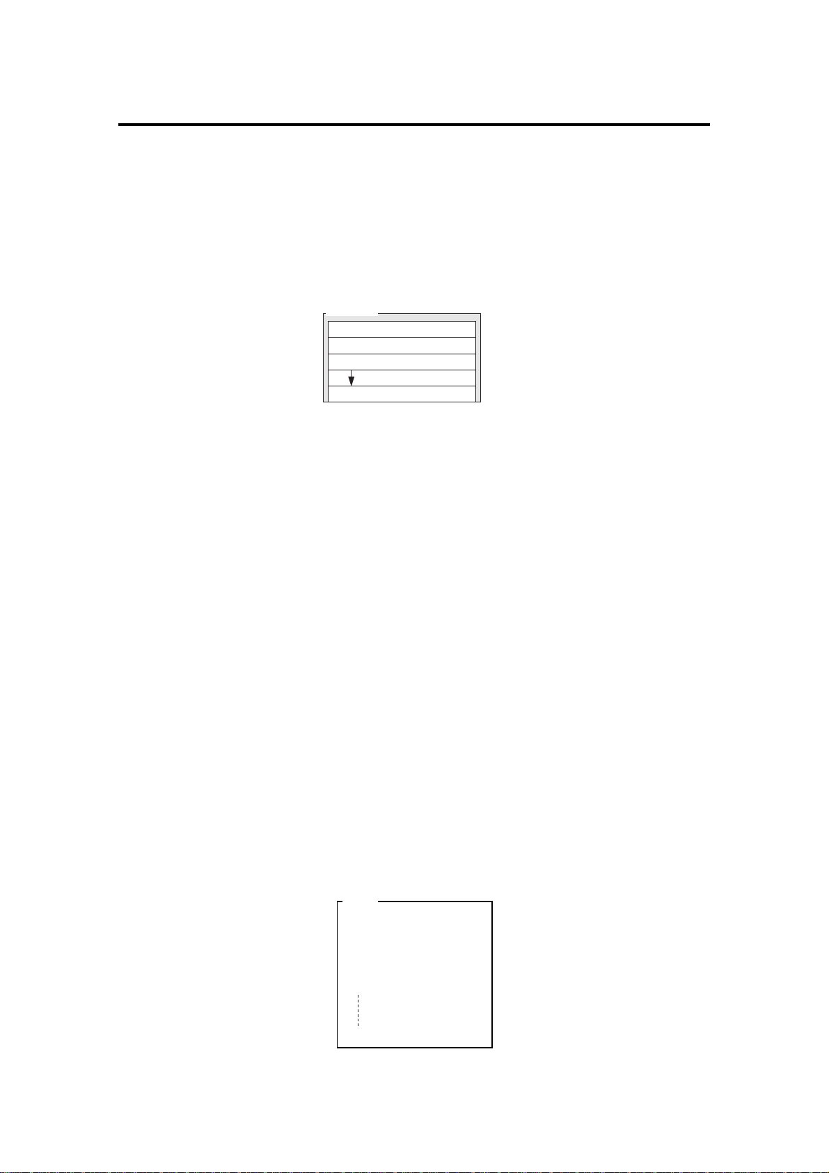
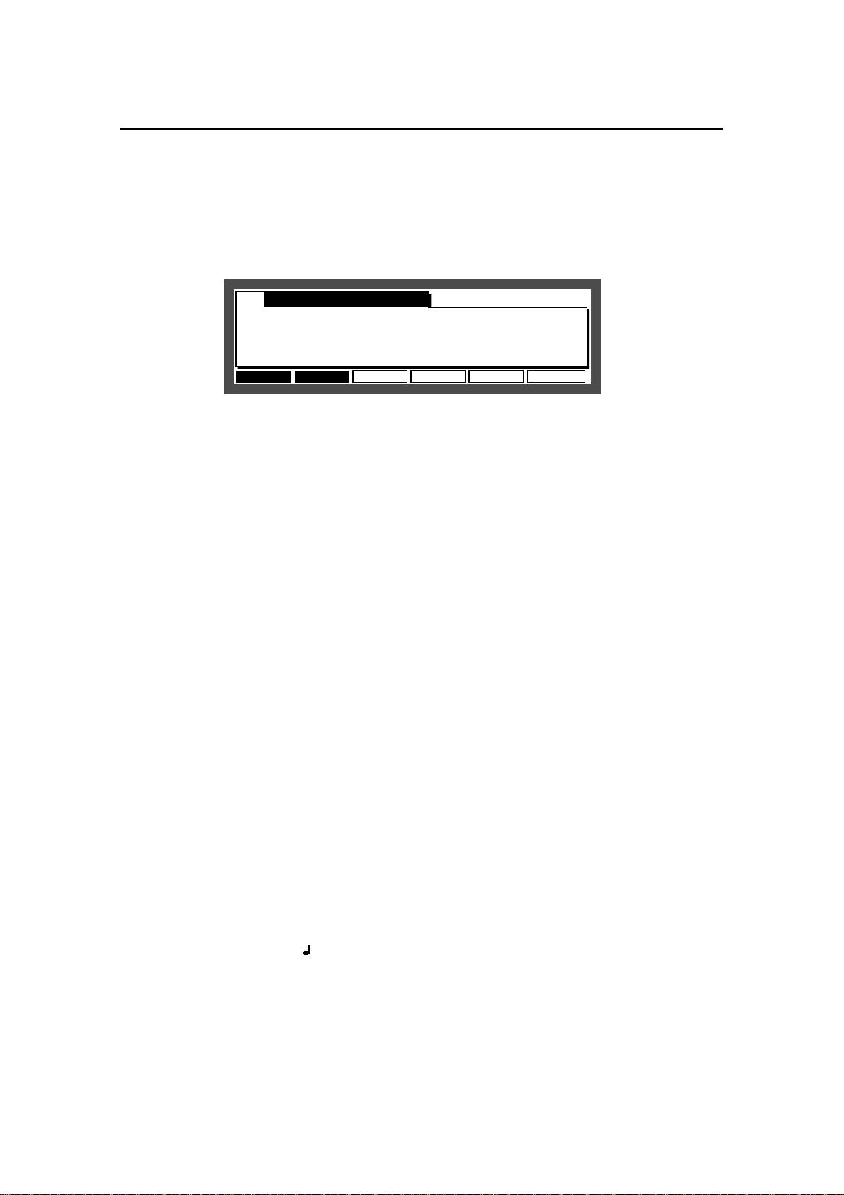
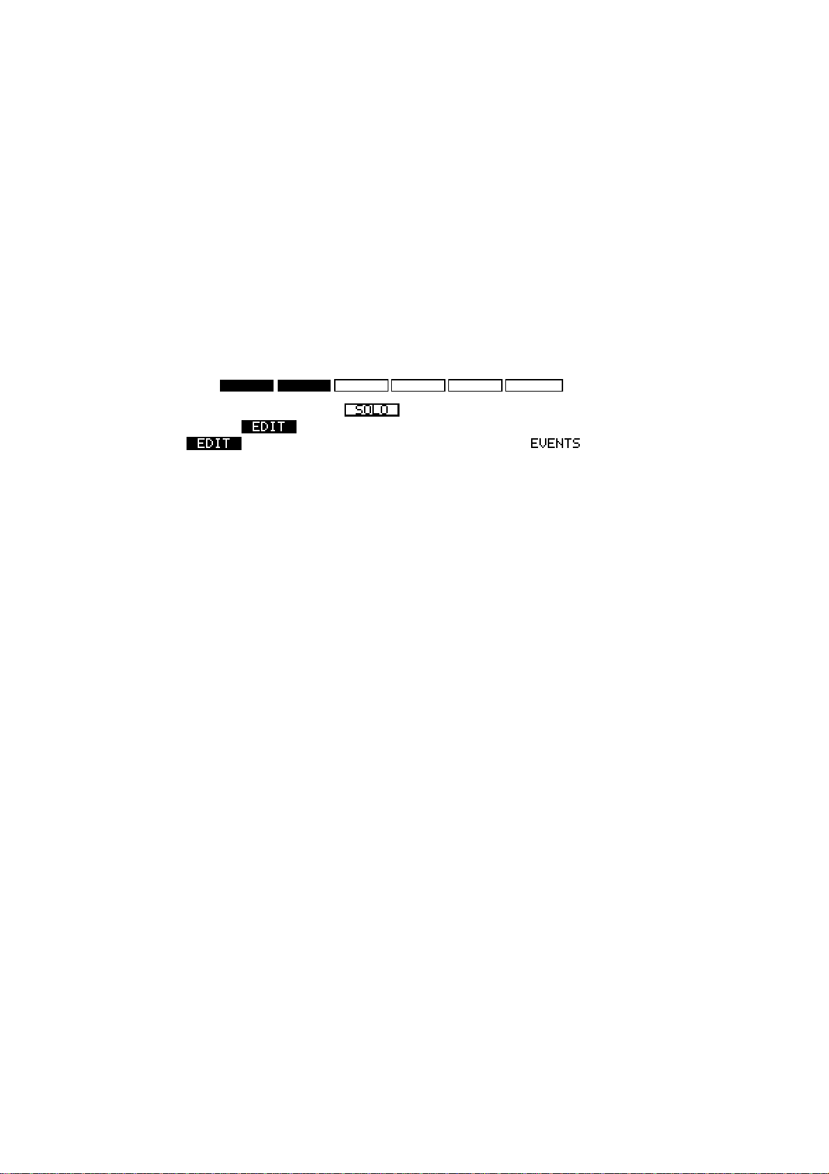
TrMUTE SOLO Tr +STEP EDIT Tr -
When a function has a frame such as , that function will be carried out. When the function
is reversed such as , you can move to that page by pressing the corresponding function
key (press [F2]). If only characters are displayed such as , it means that that is
the currently selected page.
Most of the screens in the MPC2000XL have function key displays, and the lowest line of each of
these screens indicates the function of the six function keys while the selected screen is showing.
Some screens have less than six active function keys and some have none.
Page 15
Page 27
Chapter 2: The Basics
Basic Functions
Loading and Playing Programs
All sounds and programs are stored on the memory held in RAM and the data is therefore lost
whenever the power is turned off. In order to play any sounds after turning the power on, you
must load them in from the CD or external device connected to the rear panel SCSI interface. The
procedure for loading files from a disk is described in the “Disk Operation” chapter, but to get you
started, the following steps enable you to load sounds from the enclosed CD and play them from
the drum pads:
Please note:
You must have a CD ROM player connected to the MPC2000XL in order to load the sounds
descibed here.
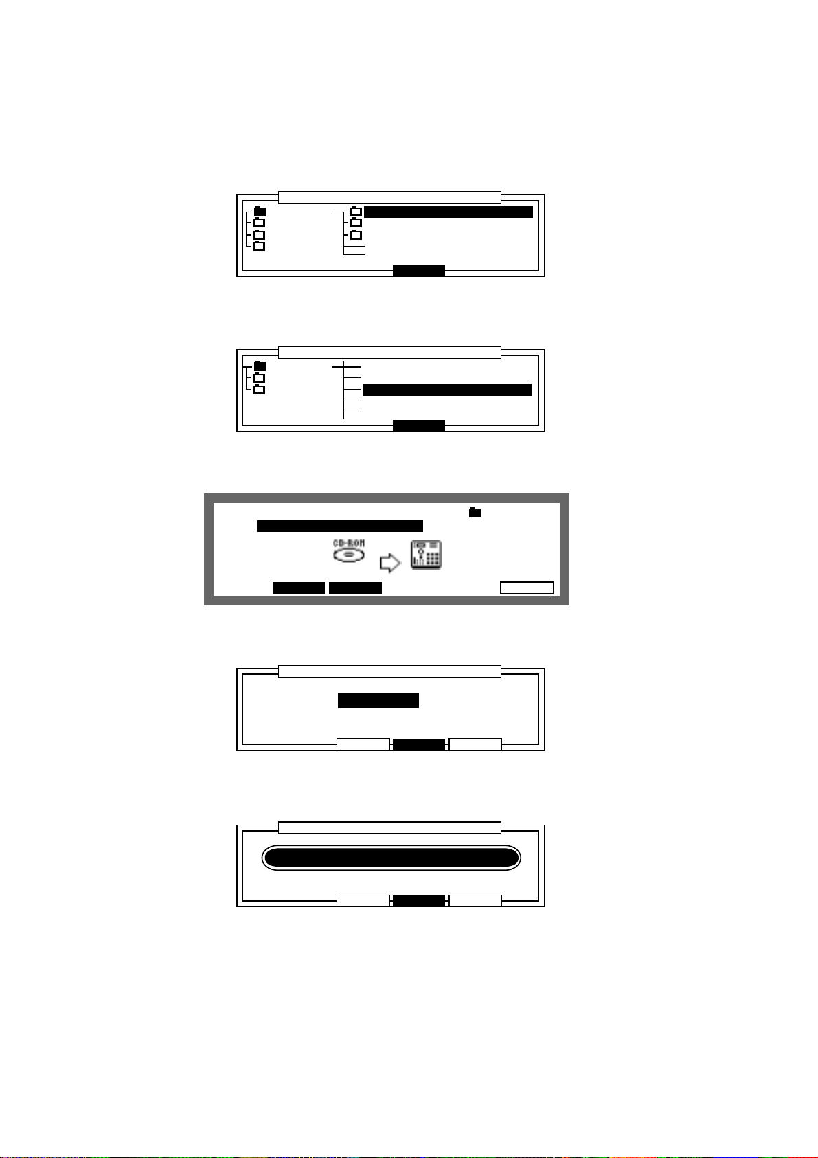
Insert the enclosed CD into the CD ROM player.
1
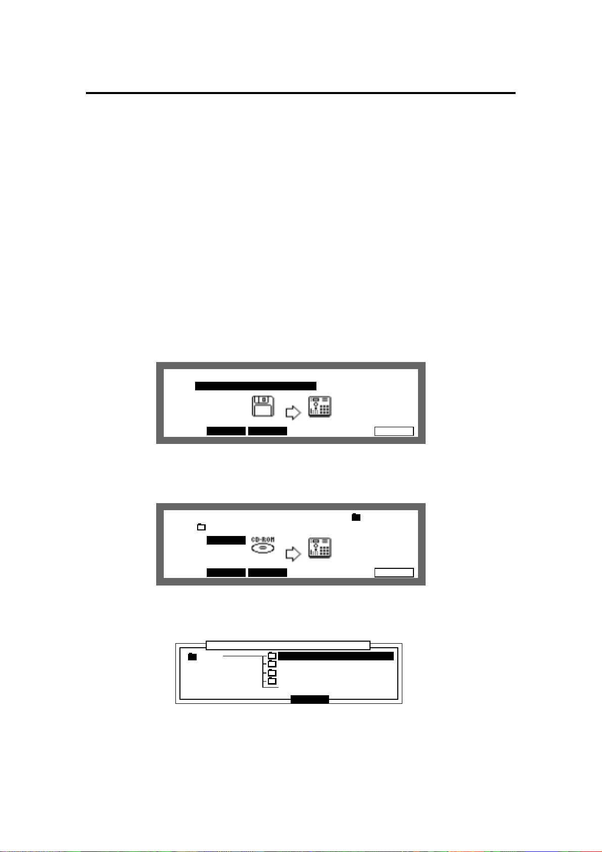
Hold down SHIFT and press LOAD (3 on the numeric keypad).
2
View:ALL FilesView:ALL Files
File: Size= K
.......................................................................................................................
Device:Floppy Free Free memory
snd= 16K
Type=No diskType=No disk seq= 2640K
Move to the Device: field with the CURSOR keys and select the SCSI ID number of the
3
SAVE FORMAT DO ITLOAD
LOAD
CD ROM with the DATA wheel.
View:ALL FilesView:ALL Files :ROOT
File: MPC2000XL_DRUMSFile: MPC2000XL_DRUMS Size= 2K
.......................................................................................................................
Device:SCSI-5 Free Free memory
snd= 16K
Type=PC seq= 2640K
Move to the File: field with the CURSOR keys and press OPEN WINDOW.
4
SAVE FORMAT DO ITLOAD
LOAD
The MPC2000XL_DRUMS file will be selected.
......................................................................................................
ROOT MPC2000XL_DRUMS
MPC3000_DISKS
MPC60_DISKS
STANDARD_DISKS
........................
..........................................................................................................
Directory
Close
............................
Page 16
Page 28
Chapter 2: The Basics
Press the RIGHT CURSOR key to open the file and then select a drum set file (ambience, dry
5
or gated) with the UP/DOWN CURSOR keys.
In this example, we will choose the ambience drums.
......................................................................................................
MPC2000X AMBIENCE_DRUMS
MPC3000_ DRY_DRUMS
MPC60_DI GATED_DRUMS
STANDARD
........................
..........................................................................................................
Press the RIGHT CURSOR key to open the file and then select
6
Directory
Close
............................
AMBIENCE_SET__1.PGM with the DATA wheel.
......................................................................................................
AMBIENCE 20_C_MUTE .WAV
DRY_DRUM 20_CHINA .WAV
GATED_DR AMBIENCE_SET__1 .PGM
AMBIENCE_SET__2 .PGM
AMBIENCE_SET__3 .PGM
........................
.........................................................................................................
Press Close [F4]. AMBIENCE_SET__1.PGM will be displayed in the File: field.
7
View:ALL FilesView:ALL Files :AMBIENCE
File:AMBIENCE_SET__1 .PGMAMBIENCE_SET__1 .PGM Size= 2K
.......................................................................................................................
Device:SCSI-5 Free Free memory
snd= 16K
Type=PC seq= 2640K
SAVE FORMAT DO ITLOAD
Directory
Close
LOAD
............................
Press DO IT [F6] and then press CLEAR [F3].
8
......................................................................................................
........................
..........................................................................................................
The loading screen will appear.
9
......................................................................................................
........................
.........................................................................................................
Replace same sound in memory
:NO(FASTER)
[CLEAR] erases existing P & S
[LOAD ] adds to existing P & S
Replace same sound in memory
:NO(FASTER)
Loading S2_AMBKIK2 .WAV
[CLEAR] erases existing P & S
[LOAD ] adds to existing P & S
Load a Program
Load a Program
CANCEL LOADCLEAR
CANCEL LOADCLEAR
............................
............................
Page 17
Page 29

Chapter 2: The Basics
When loading is finished, press MAIN SCREEN and try the sounds by hitting the drum
mr
Sq:01-(Unused)
.......................................................
™:120.0(SEQ) Timing:1/16 Tsig: 4/ 4Tsig: 4/ 4
Count:OFF Loop: ONLoop: ON Bars: 0Bars: 0
..................................................................................................
Tr:01-(Unused) ON:YES Pgm:OFF
S:DRUM1:OFF AMBIENCE_SET__1 S:DRUM1:OFF AMBIENCE_SET__1 Velo%:100
STEP EDIT Tr -
TrMUTE SOLO Tr +
Now:001.01.00
Playing the Drum Pads, the PAD BANK & FULL LEVEL Keys
Each recorded sample is called a sound. To hear some of the drum sounds you have loaded, play
the 16 drum pads on the front panel. To hear other sounds, press the A, B, C or D PAD BANK
keys, then play the pads again.
The 64 bank/pad combinations are as follows:
Drum pads in bank A: A01 through A16
Drum pads in bank B: B01 through B16
Drum pads in bank C: C01 through C16
Drum pads in bank D: D01 through D16
The 16 drum pads are dynamic—the harder you play them, the louder the sound will play. Press
the FULL LEVEL key (the idicator lights), and no matter how hard you play the pads, the sound will
play at its maximum dynamic level. Press the FULL LEVEL key again to return to normal dynamic
operation.
Page 18
Page 30
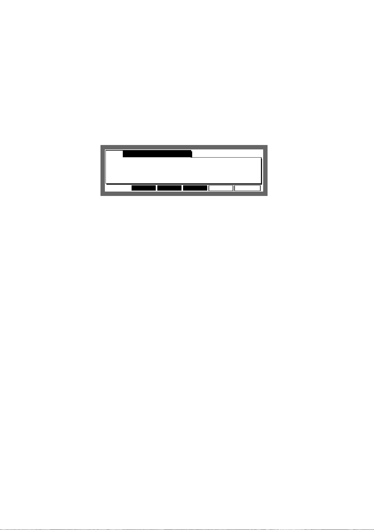
Chapter 2: The Basics
Selecting Programs
A program is an edited set with note numbers and sounds assigned to it. The MPC2000XL can
hold up to 24 programs. Each program has 64 sound assignments. If you change from one program to another, playing the four banks of pads will produce entirely different sounds.
When you played the drum pads, you were hearing the sounds assigned in Program 1. To change
to Program 2:
1. Hold down SHIFT and press PROGRAM (6 on the numeric keypad). The DRUM select screen
will appear:
Pgm: 1-NewPgm-A
.......................................................
Pad:A01=Note:37 Pad assign:PROGRAMPad assign:PROGRAM
..................................................................................................
Note:60=Snd:OFF
Mode:NORMAL
ASSIGN PARAMS AUTO
DRUM PURGE
2. Select DRUM 1, 2, 3 or 4.
3. Move the cursor to the Pgm: field. Select program 2 using the DATA wheel.
4. Play the sounds in program 2: Select Pad Bank A and play the sounds, then select Pad Banks
B, C and D.
5. Repeat step 3, except select program 3 and play the sounds. Repeat this procedure to hear the
other programs.
6. To return to the Main Screen, press MAIN SCREEN.
PLAY
The NOTE VARIATION Slider, ASSIGN and AFTER keys
The NOTE VARIATION slider can be used to change the tuning, attack, decay, or filter value for a
sound assigned to a drum pad by moving the slider while playing the pad.
Here are some examples for uses of NOTE VARIATION slider:
1. The slider can control the decay for a hi-hat sound. This would simulate the action of a
drummer’s hi-hat pedal, changing the hi-hat decay time each time the pad is played. By using
the decay switch feature in the program and setting the sound so it switches according to the
decay value, it is possible to simulate a closed hi-hat gradually opening by moving the slider.
2. The slider can be assigned to tuning for a tom tom. By moving the slider when playing the drum
pad assigned to a tom tom, it is possible to change the tunings.
3. The slider can control the filter value for a sound containing a filter setting. This will change the
sound each time the note is played, to play analog synthesizer samples and hold filter effects.
The NOTE VARIATION slider data is recorded onto a sequence with the drum notes. For details
about this, please refer to “Step Edit” of the “Editing Sequences” chapter.
Page 19
Page 31

Chapter 2: The Basics
The ASSIGN Key
To assign a pad and parameter to the NOTE VARIATION slider, hold down SHIFT and press
AFTER (ASSIGN). The following screen will appear:
Assign note:Assign note:38/A06-NORI_SN_0
...................................................................................
Parameter:DECAY
Assign NV slider to ctrl change:OFF Assign NV slider to ctrl change:OFF
To assign the slider to a drum pad and parameter:
1. Press the drum pad you want to assign to (the note number, pad number and sound name of
the pad you pressed will appear in the Assign note: field). You can also select the
sound by selecting the Assign note: field with the cursor and using the DATA wheel.
2. Move the cursor to the Parameter: field and select the desired parameter (TUNING,
DECAY, ATTACK or FILTER) using the DATA wheel, then assign the related settings.
3. Press MAIN SCREEN to return to the Main Screen.
4. Play the selected pad while moving the NOTE VARIATION slider. Each time the pad is played,
the selected parameter (tuning, attack, decay or filter) will change according to the slider position.
High rangn: 50rangn: 50
Low rangn: 16rangn: 16
Additional information about the four fields:
Assign note:
•
This field contains the note number to which the slider is assigned (35-98). To change the
assignment, press a drum pad. The pad number of the pad you pressed in the Assign
note: field and the name of the sound currently assigned to the note number will appear.
Alternately, you can change it by moving the cursor directly to the field and rotating the DATA
wheel. To turn this function off, turn the DATA wheel to the left until OFF appears.
Parameter:
•
This field determines which of the four possible parameters the slider will control. The four
choices are:
TUNING This slider changes the tuning of the sound. The tuning you get is based on the
tuning that is set in the Tune: parameter of the program.
DECAY This enables you to change the decay time with the slider. This changes re-
gardless of the value set in the Decay: parameter of the program.
ATTACK This enables you to change the attack time with the slider. This changes re-
gardless of the value set in the Attack: parameter of the program.
FILTER This enables you to change the cut off frequency of the sound with the slider.
This changes the Freq: value of the parameter in the program.
Page 20
Page 32

Chapter 2: The Basics
Low range: and High range:
•
These two fields control the range of the slider effect. The Low range: field determines
the parameter value that will be produced when the pad is hit while the slider is at the bottom of
its travel; the High range: field determines the parameter value that will be produced
when the pad is hit while the slider is at the top of its travel. The parameter value consecutively
changes in any position within the range. The available range for this field is determined by the
parameter selected in the Parameter: field.
TUNING : -120 ~ +120
ATTACK : 0 ~ 100
DECAY : 0 ~ 100
FILTER : -50 ~ +50
Note: The attack or decay changes within the range of 0 and 5000msec.
Assign NY slider to ctrl change:
•
This field selects the MIDI Control Change Number which controls the NOTE VARIATION
slider from an external MIDI controller.
The AFTER key
Normally, the slider only affects notes which are actually played and has no effect on notes played
back from sequences. However, if the AFTER key is pressed (and the indicator lights), the slider
also effects the drum notes playing back from sequences. In this case, the function effects the
drum note of the note number (drum pad) assigned to the NOTE VARIATION slider. Also, this
NOTE VARIATION slider data can be recorded if you are in the Overdub mode.
To return to normal operation, press the AFTER key again and the light will go off.
Page 21
Page 33

Chapter 2: The Basics
The 16 LEVELS key
By using the 16 LEVELS function, you can play a sound in 16 parameter levels of velocity, tone,
attack, decay, or filter.
To use the 16 LEVELS function, in the Main Screen, press the 16 LEVELS key to display the
following screen.
......................................................................................................
Note :47/A10-NR_TOM_M
Param:NOTE VAR
Type:TUNING Original key pad:4
........................
.........................................................................................................
Assign 16 levels
CANCEL TurnON
............................
• Note:
Use the 16 level feature to select the pads you are playing to 16 levels. Select the sound by
directly playing the drum pad. It is also possible to move the cursor to the field and select the
pad with the DATA wheel.
• Param:
When VELOCITY is selected, it is possible to apply 16 levels of velocity to the sound set in
Note:. The velocity is played the weakest on PAD1 and strongest on PAD16.
When NOTE VAR is selected, set the parameter with the following Type:.
• Type:
This allows you to select the following parameter.
TUNING This allows you to play the sound set in Note: at 16 levels of tuning. The
original tuning is assigned to the pad set in the Original key pad:
field and the tuning changes by a semi-tone.
DECAY This allows you to play the sound set in Note: at 16 levels of decay time.
The range of decay time is set on the assign screen of the note variation by
pressing the ASSIGN (AFTER) key while holding down the SHIFT key.
ATTACK This allows you to set the attack time of a sound set in Note: at 16 levels
and play them. The range of the attack time is set on the assign screen of
the note variation by pressing the ASSIGN (AFTER) key while holding down
the SHIFT key.
FILTER This allows you to set the cut off frequency of the filter of a sound set in
Note: at 16 levels and play them. The range of the cut off frequency is set
on the assign screen of the note variation by pressing the ASSIGN (AFTER)
key while holding down the SHIFT key.
After you have set the parameter, press TurnON [F5]. The 16 LEVELS LED indicator will light and
allow you to play using the 16 levels function.
Press the 16 LEVELS key again to turn the 16 LEVELS function off.
Page 22
Page 34

Chapter 3: Recording Sequences
Chapter 3
Recording Sequences
Page 23
Page 35

Chapter 3: Recording Sequences
How Sequences are Organized
A sequence is the most basic unit for creating on the MPC2000XL. The performance data from a
MIDI keyboard or pad is recorded on each track within a sequence. Each sequence has 64 tracks,
to which performance data can be recorded. It is possible to create up to 99 sequences.
Sequence
Track 01
Track 02
Track 03
Piano
Bass
Organ
Track 64
(Unused)
There are two main ways to create music on the MPC2000XL. One way is to create a long sequence as a whole song, the other way is to create short sequences and join them together to
make a song. Therefore, a sequence can be a long piece of more than 100 bars or a two-bar drum
loop
One sequence as a whole piece.
SONG
Sequence
A multiple sequence piece (setting short sequences with the Song function).
SONG
Sequence Sequence Sequence
Seq.
Sequence
There are 64 tracks in a sequence to which individual performances can be recorded to. For
example, track 1 could be the piano, track 2 could be the bass, and track 3 the organ. Normally,
each track is recorded one at a time.
It is also possible to record a new track while playing previously recorded tracks. Each track can
be turned on or off individually.
You can record different piano solos to track 1 and track 2 and compare the combination with the
other tracks.
You can select either a Drum track or MIDI track. The drum track plays the recorded data of the
internal sampler. The MIDI track plays the sound of the external MIDI sound source connected to
MIDI OUT.
In order for the sequencer to play external synthesizers, you must send the notes from the A/B
MIDI channels (16 MIDI channels for each of the 2 MIDI output jacks). On the MPC2000XL, each
track can be independently assigned to one of these 32 output MIDI channels.
Page 24
Page 36

Chapter 3: Recording Sequences
Bar.Beat.Tick
The sequencer of the MPC2000XL divides the quarter note into 96 parts. Each one of these
divisions is called a tick.
In many of the sequence editing screens it is necessary to enter the start and end of the region that
you want to edit. This is done using the time field, containing a bar number, beat number and tick
number.
001.01.00
Bar Beat Tick
To specify the range to be edited, select bar, beat or tick with the cursor and set the value with the
DATA wheel. The edit range set in the time field starts at the time entered on the right and
continues to one tick before the time entered on the right. Therefore, if the settings were
001.01.00 – 003.01.00 then you cannot edit an event entered at 003.01.00. Also when you are
editing each bar, the First bar: field is the first bar and the Last bar: field will be the last bar edited.
In this case, the bar set in the Last bar: field is included in the edit range. When the First bar: is set
to one and the Last bar: to two, the data of the first and second bars will be edited.
Page 25
Page 37

Chapter 3: Recording Sequences
Examples of Sequence Recordings
The MPC2000XL is a sequencer with an internal sampler. You can simply use it as a drum
machine, or as a sequencer connected to a MIDI device.
It is also possible to set a loop to a sequence and repeatedly play a phrase.
Example 1: Recording a Drum Pad Performance
First let's record a drum pad performance. This is the most basic use of the MPC2000XL, by using
it simply as a rhythm machine.
1. Turn the power on and load the drum sounds from the enclosed sound disk. (Refer to the
chapter “Loading and Playing Programs” for details on how to load the sounds.) When you
have finished, check to see if the drum sounds can be played back by playing the drum pads.
2. Press MAIN SCREEN and display the Main Screen. The recording and play back of a se-
quence will always be done here.
Sq:01-(Sequence01)
.......................................................
™:120.0(MAS) Timing:1/16 Tsig: 4/ 4Tsig: 4/ 4
Count:OFF Loop: OFFLoop: OFF Bars: 0Bars: 0
..................................................................................................
Tr:01-(Unused) ON:YES Pgm:OFF
S:DRUM1:OFF Velo%:100
STEP EDIT Tr -
TrMUTE SOLO Tr +
Now:001.01.00
3. Select the Sq: field with the CURSOR keys and rotate the DATA wheel and select an unused
sequence (Unused).
4. Select the field to the right of S: with the CURSOR key and rotate the DATA wheel to the right
to select Drum 1.
Sq:01-Sequence01
.......................................................
™:120.0(MAS) Timing:1/16 Tsig: 4/ 4Tsig: 4/ 4
Count:OFF Loop:OFF Bars: 2Bars: 2
..................................................................................................
Tr:01-(Unused) ON:YES Pgm:OFF
S:DRUM1:OFF New Pgm-A:OFF New Pgm-A Velo%:100
STEP EDIT Tr -Tr -
TrMUTE SOLO Tr +Tr +
Now:001.01.00
5. To set the number of bars for recording, select the Bars: field with the CURSOR keys and
turn the DATA wheel to display the following screen. Select the number of bars with the DATA
wheel and press DO IT [F5]
...................................................................................................
Current= 2 > New bars: Current= 2 > New bars: 2
..................................................................................................
........................
.......................................................................................................
Change Bars
CANCELIN/DEL DO IT
............................
Page 26
Page 38

Chapter 3: Recording Sequences
6. Select the Loop: field with the CURSOR keys and rotate the DATA wheel to the left to select
OFF.
Sq:01-Sequence01
.......................................................
™:120.0(MAS) Timing:OFF Tsig: 4/ 4Tsig: 4/ 4
Count:OFF Loop:OFF Bars: 2Bars: 2
..................................................................................................
Tr:01:(Unused) ON:YES Pgm:OFF
S:DRUM1:OFF New Pgm-A S:DRUM1:OFF New Pgm-A Velo%:100
STEP EDIT Tr -
TrMUTE SOLO Tr +
Now:001.01.00
7. Select the Count: field with the CURSOR keys and rotate the DATA wheel to the right to
turn it ON.
Sq:01-Sequence01
.......................................................
™:120.0(MAS) Timing:OFF Tsig: 4/ 4Tsig: 4/ 4
Count: ON Loop:OFF Bars: 2Bars: 2
..................................................................................................
Tr:01:(Unused) ON:YES Pgm:OFF
S:DRUM1:OFF New Pgm-A S:DRUM1:OFF New Pgm-A Velo%:100
STEP EDIT Tr -
TrMUTE SOLO Tr +
Now:001.01.00
8. While still on the Count: field, press OPEN WINDOW to open the Count/Metronome win-
dow.
......................................................................................................
Count IN:REC ONLY In play: NO
Rate:1/4 In rec :YES
....................................................................................
Wait for key:OFF
........................
........................................................................................................
Count/Metronome
CLOSE SOUND
............................
9. Select the Count in: field with the CURSOR keys and select REC ONLY with the DATA
WHEEL. Then, select the In rec: field and rotate the DATA wheel to the right and set it to
YES.
......................................................................................................
Count IN:REC ONLYCount IN:REC ONLY In play: NOIn play: NO
Rate:1/4 In rec :In rec :YES
....................................................................................
Wait for key:OFFWait for key:OFF
........................
........................................................................................................
Count/Metronome
CLOSE SOUND
............................
10. Press SOUND [F5] and select a metronome sound (CLICK, DRUM 1, 2, 3 or 4).
If you select CLICK, select and adjust the Volume: level and Output: (where the
sound will be output from).
If you select DRUM 1, 2, 3 or 4, you can select 2 drum sounds (Accent: and
Normal:) that will play as the metronome sound. You can select the sounds by pressing
one of the drum pads or selecting the sound in the corresponding field. Then move to and
adjust the velocity level of the sounds.
11. Press CLOSE [F4] twice to return to the Main Screen.
12. Hold down REC and press PLAY START to start recording. After a one bar count, recording
will start and the bar.beat.tick numbers in the Now: field will start to increase. Play the drum
pads to the click or drum sounds.
13. Bars will automatically be added when the number of bars set in step 5 is exceeded. To stop
in the middle of a recording, press STOP. You can play back the recorded sequence by
pressing the PLAY START key.
Page 27
Page 39

Chapter 3: Recording Sequences
14. Hold down REC and press PLAY START if you want to record over the previous recording.
15. To overdub on top of a recorded sequence, hold down OVER DUB and press PLAY START
(the original recording is kept and the new sounds added to it).
Example 2: Recording a Loop
This allows you to repeatedly play a preset number of bars and keep dubbing sounds over it.
1. Turn the power on and load the drum sounds from the enclosed sound disk. (Refer to the
chapter “Loading and Playing Programs” for details on how to load the sounds.) When you
have finished, check to see if the drum sounds can be played back by playing the drum pads.
2. Press MAIN SCREEN and display the Main Screen. The recording and playback of a se-
quence will always be done here.
Sq:01-(Sequence01)
.......................................................
™:120.0(MAS) Timing:1/16 Tsig: 4/ 4Tsig: 4/ 4
Count:OFF Loop: OFFLoop: OFF Bars: 0Bars: 0
..................................................................................................
Tr:01-(Unused) ON:YES Pgm:OFF
S:DRUM1:OFF New Pgm-A S:DRUM1:OFF New Pgm-A Velo%:100
STEP EDIT Tr -Tr -
TrMUTE SOLO Tr +Tr +
Now:001.01.00
3. Select the Sq: field with the CURSOR keys and rotate the DATA wheel and select an unused
sequence (Unused).
4. Select the track type field (S:) with the CURSOR key and rotate the DATA wheel to the right
to select Drum 1.
Sq:01-Sequence01
.......................................................
™:120.0(MAS) Timing:OFF Tsig: 4/ 4
Count:OFF Loop:OFF Bars: 2
..................................................................................................
Tr:01:(Unused) ON:YES Pgm:OFF
S:DRUM1:OFF New Pgm-A Velo%:100
STEP EDIT Tr -
TrMUTE SOLO Tr +
Now:001.01.00
5. Select the Bars: field with the CURSOR keys and turn the DATA wheel to display the bar
setting window. In this example, we will create a two-bar loop. Select “2” with the DATA wheel
and press DO IT [F5].
If you record past the set number of bars, the sequence will return to the first bar.
Sq:01-Sequence01
.......................................................
™:120.0(MAS) Timing:OFF Tsig: 4/ 4
Count:OFF Loop:OFF Bars: 2
..................................................................................................
Tr:01:(Unused) ON:YES Pgm:OFF
S:DRUM1:OFF New Pgm-A Velo%:100
STEP EDIT Tr -
TrMUTE SOLO Tr +
Now:001.01.00
6. Select the Loop: field with the CURSOR keys and rotate the DATA wheel to the right to turn
it ON.
Sq:01-Sequence01
.......................................................
™:120.0(MAS) Timing:OFF Tsig: 4/ 4
Count:OFF Loop: ON Bars: 2
..................................................................................................
Tr:01:(Unused) ON:YES Pgm:OFF
S:DRUM1:OFF New Pgm-A Velo%:100
STEP EDIT Tr -
TrMUTE SOLO Tr +
Now:001.01.00
Page 28
Page 40

Chapter 3: Recording Sequences
7. While the Loop: field is selected, press OPEN WINDOW to open the Loop window.
......................................................................................................
First bar: First bar: 1
Last bar:ENDLast bar:END
Number of bars: 2Number of bars: 2
........................
........................................................................................................
Loop
CLOSE
............................
8. Select the First bar: field with the CURSOR keys and set to 1 with the DATA wheel.
9. Select the Last bar: field with the CURSOR keys and set to END with the DATA wheel.
Close the Loop window by pressing CLOSE [F4].
10. Select the Count: field with the CURSOR keys and rotate the DATA wheel to the right to
turn it ON.
Sq:01-Sequence01
.......................................................
™:120.0(MAS) Timing:OFF Tsig: 4/ 4Tsig: 4/ 4
Count:
..................................................................................................
Tr:01:(Unused) ON:YES Pgm:OFF
S:DRUM1:OFF New Pgm-A S:DRUM1:OFF New Pgm-A Velo%:100
STEP EDIT Tr -
@
ON Loop: ONLoop: ON Bars: 2Bars: 2
TrMUTE SOLO Tr +
Now:001.01.00
11. While the Count: field is selected, press OPEN WINDOW to open the Count/Metronome
window.
......................................................................................................
Count IN:Count IN:REC ONLYREC ONLY In play: NOIn play: NO
Rate:1/4 In rec :YESIn rec :YES
....................................................................................
Wait for key:OFFWait for key:OFF
........................
........................................................................................................
Count/Metronome
CLOSE SOUND
............................
12. Select the Count in: field with the CURSOR keys and select REC ONLY with the
DATA wheel. Also select the In rec: field and set to YES by rotating the DATA wheel to
the right.
......................................................................................................
Count IN:REC ONLYCount IN:REC ONLY In play: NOIn play: NO
Rate:1/4 In rec :In rec :YES
....................................................................................
Wait for key:OFFWait for key:OFF
........................
........................................................................................................
Count/Metronome
CLOSE SOUND
............................
13. Press CLOSE [F4] to close the Count/Metronome window and return to the main window.
14. Start recording by holding down REC and pressing OVER DUB. After a one bar count, record-
ing will start and the bar.beat.tick numbers in the Now: field will start to increase. Play the
drum pads to the click or drum sounds.
When the two bars have been recorded, the numbers will automatically return to the first bar
and you can keep overdubbing as the bars loop.
15. To finish recording, press STOP. You can play back the loop by pressing PLAY START.
If you want to delete the recording, press UNDO SEQ and you can start again (see page 5 No.
10 for full explanation of this key).
Page 29
Page 41

Chapter 3: Recording Sequences
Example 3: Recording with External MIDI Equipment
This is an example of recording using the internal sequencer and an external MIDI sound source
in addition to the internal drum sounds.
1. Refer to the example on page 12 and connect the MIDI device to the MPC2000XL, turn the
power on and load the drum sounds from the attached sound disk. (Refer to the chapter
“Loading and Playing Programs” for details on how to load the sounds.) When you have
finished loading, check to see if the drum sounds can be played back by playing the drum
pads.
2. Use the drum pads to record the drum sounds in the same manner as shown in Example 1.
3. Select the Tr: field with the cursor and select a track which is not being used by rotating the
DATA wheel to the right.
Sq:01-Sequence01
.......................................................
™:120.0(MAS) Timing:OFF Tsig: 4/ 4Tsig: 4/ 4
Count:OFF Loop:OFF Bars: 2
..................................................................................................
Tr:02-(Unused) ON:YES Pgm:OFF
S:DRUM1:OFF New Pgm-A S:DRUM1:OFF New Pgm-A Velo%:100
STEP EDIT Tr -
TrMUTE SOLO Tr +
Now:001.01.00
4. Select the Track Type field with the cursor and select MIDI by rotating the DATA wheel to
the left.
Sq:01-Sequence01
.......................................................
™:120.0(MAS) Timing:OFF Tsig: 4/ 4Tsig: 4/ 4
Count:OFF Loop:OFF Bars: 2Bars: 2
..................................................................................................
Tr:02-Track-02 ON:YES Pgm:OFF
S:MIDI :OFF Velo%:100
STEP EDIT Tr -
TrMUTE SOLO Tr +
Now:001.01.00
5. Select the MIDI Channel field with the cursor and set the MIDI channel of the MIDI device with
the DATA wheel. As the MPC2000XL’s receiving channel is normally set to OMNI, the
keyboard’s MIDI send channel can be set to any channel.
As there are 2 MIDI outputs, you have the choice of selecting channels 1-16A or 1-16B, depending on which output your device is connected to.
Once selected, play the keyboard and make sure that the sounds can be heard.
Sq:01-Sequence01
.......................................................
™:120.0(MAS) Timing:OFF Tsig: 4/ 4Tsig: 4/ 4
Count:OFF Loop:OFF Bars: 2Bars: 2
..................................................................................................
Tr:02-Track-02 ON:YES Pgm:OFF
S:MIDI : S:MIDI :10A-Device10 Velo%:100
STEP EDIT Tr -
TrMUTE SOLO Tr +
Now:001.01.00
6. Start recording by pressing PLAY START while holding down REC. After one bar count,
recording will start and the bar.beat.tick numbers in the Now: field will start to increase. Play
the MIDI device to the prerecorded drum sound.
Page 30
Page 42

Chapter 3: Recording Sequences
7. When the set number of bars is exceeded, bars will automatically be added. To stop the
recording, press STOP. You can play back the sequence by pressing PLAY START.
8. To record again, hold down REC and press PLAY START.
9. Repeat steps 3 to 8 to overdub the external MIDI device sound.
Page 31
Page 43

Chapter 3: Recording Sequences
The MAIN SCREEN
After the power is turned on, the LCD screen shows the following contents:
Sq:01-(Sequence01)
.......................................................
™:120.0(MAS) Timing:1/16 Tsig: 4/ 4Tsig: 4/ 4
Count:OFF Loop: OFFLoop: OFF Bars: 0Bars: 0
..................................................................................................
Tr:01-(Unused) ON:YES Pgm:OFF
S:DRUM1:OFF Velo%:100
STEP EDIT Tr -Tr -
TrMUTE SOLO Tr +Tr +
Now:001.01.00
This is called the Main screen. It is the main operating screen of the MPC2000XL and most playing
and recording of sequences is done while this screen is showing. To return to this screen, press
the MAIN SCREEN key. The following is an explanation of each of the data fields and function
keys contained in this screen:
Selecting a Sequence
Sq:01-(Sequence01)
.......................................................
™:120.0(MAS) Timing:1/16 Tsig: 4/ 4Tsig: 4/ 4
Count:OFF Loop: OFFLoop: OFF Bars: 0Bars: 0
..................................................................................................
Tr:01-(Unused) ON:YES Pgm:OFF
S:DRUM1:OFF Velo%:100
STEP EDIT Tr -
TrMUTE SOLO Tr +
Move the cursor to the Sq: field and turn the DATA wheel to select the sequence. The sequence
number and sequence name will appear. (Unused) will appear when there is no data recorded to the sequence.
Now:001.01.00
Renaming a Sequence
To open the Sequence window select the Sq: field and press OPEN WINDOW.
......................................................................................................
Sq:01-(Sequence01)
.......................................................
™:120.0(MAS) Timing:1/16 Tsig: 4/ 4
Count:OFF Loop: ON Bars: 0
..................................................................................................
Tr:01-Track01 ON:YES Pgm:OFF
S:DRUM1:OFF Velo%:100
Sequence name:Sequence01
....................................................................................
Default name:Sequence
........................
STEP EDIT Tr -
DELETE
........................................................................................................
• Sequence name:
To change the name of the sequence.
• Default name:
When you are recording a new sequence, the name set here will automatically be used.
When a name is actually used for a sequence, the sequence number will be added after the
name. For example, if the default name is set to “Sequence”, the name will be “Sequence01”
(01 is the sequence number).
Sequence
TrMUTE SOLO Tr +Tr +
CLOSE COPY
Now:001.01.00
............................
Page 32
Page 44

Chapter 3: Recording Sequences
Name window
Tap a drum pad or rotate the DATA wheel at the name field to display the Name window.
The Name window is common to all naming fields.
...................................................................................................
Sq:01-(Sequence01)
.......................................................
™:120.0(MAS) Timing:1/16 Tsig: 4/ 4Tsig: 4/ 4
Count:OFF Loop: ONLoop: ON Bars: 0Bars: 0
..................................................................................................
Tr:01-(Unused) ON:YES Pgm:OFF
S:DRUM1:OFF Velo%:100
..........................
STEP EDIT Tr -
........................................................................................................
New name:Íequence01
Press PADs or use DATA knob.Press PADs or use DATA knob.
TrMUTE SOLO Tr +
Name
CANCEL ENTERCOPY PASTE
Now:001.01.00
............................
Enter letters with the DATA wheel and move to the left/right with the CURSOR LEFT or
RIGHT keys.
You can directly enter letters from the drum pads. The letter shown on the top right of the
pad will be entered when the pad is pressed. For example, A will be entered if you press
PAD 1 once and B if you press it again.
Press 16 LEVELS to enter a space.
To switch between lower and upper case letters, press FULL LEVEL.
COPY [F2] copies the name to the clipboard and PASTE [F3] pastes the name from the
clipboard.
Enter the name and press the ENTER [F5] key to confirm.
Deleting a Sequence
To open the Sequence window select the Sq: field and press OPEN WINDOW.
Press DELETE [F2].
......................................................................................................
Sq:01-(Sequence01)
.......................................................
™:120.0(MAS) Timing:1/16 Tsig: 4/ 4Tsig: 4/ 4
....................................................................................
Count:OFF Loop: ONLoop: ON Bars: 0Bars: 0
..................................................................................................
Tr:01-(Unused) ON:YES Pgm:OFF
S:DRUM1:OFF Velo%:100
........................
STEP EDIT Tr -
........................................................................................................
....................................................................................
Sequence name:Sequence name:Sequence01
Default name:Sequence01Default name:Sequence01
Sq:01-Sequence01
Pressing DO IT will erasePressing DO IT will erase
this sequence!!this sequence!!
........................
DELETE
........................................................................................
Sequence
Delete SequenceDelete Sequence
TrMUTE SOLO Tr +
ALL SQ
CANCEL DO IT
CLOSE COPY
Now:001.01.00
............................
............................
The selected sequence data will be erased if you press DO IT[F5] and the sequence name will
change to (Unused).
The following warning will appear if you press ALL SQ [F3] and all of the sequence data will be
erased when you press DO IT [F5].
......................................................................................................
Sq:01-(Sequence01)
.......................................................
™:120.0(MAS) Timing:1/16 Tsig: 4/ 4Tsig: 4/ 4
....................................................................................
Count:OFF Loop: ONLoop: ON Bars: 0Bars: 0
..................................................................................................
Tr:01-(Unused) ON:YES Pgm:OFF
S:DRUM1:OFF Velo%:100
........................
STEP EDIT Tr -
........................................................................................................
....................................................................................
Sequence name:Sequence name:Sequence01
Default name:Sequence01Default name:Sequence01
........................
DELETE
........................................................................................
Sequence
Delete ALL SequencesDelete ALL Sequences
Pressing DO IT Will erasePressing DO IT Will erase
ALL sequences!!ALL sequences!!
TrMUTE SOLO Tr +
CANCEL DO IT
CLOSE COPY
Now:001.01.00
............................
............................
Page 33
Page 45

Chapter 3: Recording Sequences
Copying a Sequence
To open the Sequence window select the Sq: field and press OPEN WINDOW.
Press COPY [F5] to open the Copy Sequence window.
......................................................................................................
Sq:01-(Sequence01)
.......................................................
™:120.0(MAS) Timing:1/16 Tsig: 4/ 4Tsig: 4/ 4
....................................................................................
Count:OFF Loop: ONLoop: ON Bars: 0Bars: 0
..................................................................................................
Tr:01-(Unused) ON:YES Pgm:OFF
S:DRUM1:OFF Velo%:100
........................
STEP EDIT Tr -
........................................................................................................
....................................................................................
Sequence name:Sequence name:Sequence01
Default name:Sequence01Default name:Sequence01
........................
DELETE
........................................................................................
Sequence
Copy SequenceCopy Sequence
Sq:01-Sequence01
COPY
Sq:02-(Unused)
TrMUTE SOLO Tr +
CANCELPARAMS DO IT
CLOSE COPY
Now:001.01.00
............................
............................
Select the sequence that you want to copy (top level) by pressing CURSOR UP and select the
sequence with the DATA wheel.
Select the copy destination (bottom level) by pressing CURSOR DOWN and select the sequence
you want to copy the da ta to with the DATA wheel.
The sequence data will be copied when you press DO IT [F5].
CAUTION: If there is data in the sequence you have selected as the destination, the
data will be erased when you press
DO IT
. Be careful when you are
copying to a sequence with a name other than “Unused.”
When PARAMS [F3] is pressed, only the parameters will be copied to the selected sequence.
The sequence data will not be copied.
Next sequence function
When the cursor is in the Sq: field while a sequence is playing, you can select the sequence to
play next by rotating the DATA wheel. The following window appears when you rotate the DATA
wheel.
Sq:01-(Sequence01)
.......................................................
™:120.0(MAS) Timing:1/16 Tsig: 4/ 4
Count:OFF Loop: OFF Bars: 0
..................................................................................................
Tr:01-(Unused) ON:YES Pgm:OFF
S:DRUM1:OFF Velo%:100
Next Sq: 2 Tr -
TrMUTE SOLO Tr +
Now:001.01.00
Pressing the NEXT SEQ key shows the following screen.
Sq:01-Sequence01
.......................................................
™:120.0(MAS) Timing:1/16
..................................................................................................
Next Sq:02-Sequence02
SUDDEN PAD
Now:001.01.00
CLEAR
Select the sequence with the DATA wheel. In the above illustration, 02-Sequence02 is played
back after 01-Sequence01 is played to the end. It is possible to play sequences consecutively in
this manner. To stop the Next Sequence function select the number originally selected (the currently playing sequence in the Next sq: field) or press CLEAR [F5] to clear the entry.
Sq: field
During the stop mode, the sequence that will be played back when the play key is pressed is
displayed.
During the playback mode, the sequence being played back is displayed.
Page 34
Page 46

Chapter 3: Recording Sequences
Next sq: field
The sequence that will be played next is displayed.
SUDDEN [F4] key
The currently playing sequence will stop playing and the next sequence will immediately be
played.
CLEAR [F5]
Empties the data in the Next sq:field. If the Next sq: field is empty , and the sequence
playing is set to loop on, that sequence will be continuously looped until a separate sequence
is input to Next sq: or the STOP key is pressed.
PAD [F6]
Opens the pad window which shows you which sequences are assigned to which drum pads.
This allows you to select the next sequence by pressing the relevant drum pads.
Selecting the Next Sequence with the Drum Pads
The pad screen shows you which sequences are assigned to which drum pads (sequences 1-64
correspond to drum pads A1-D16). This allows you to select the next sequence by pressing a
drum pad (the first eight letters of the sequence name will be displayed).
Note: You can not select sequences 65-99 with the drum pads.
From the Next Sequence screen, press PAD [F6], the following screen appears.
Sq:01-Sequence01
.......................................................
Tr: (Unused) (Unused) (Unused) (Unused)
01-16 Sequence Sequence Sequence (Unused)
Sequence (Unused) Sequence (Unused)
BANK
Sequence Sequence (Unused) Sequence
A
01-Sequence01
Now:001.01.00
CLEARSUDDEN
CLOSE
SUDDEN [F4]
During playback, press this key to start playback of the selected next sequence without waiting for the current one to finish.
Sq:01-Sequence01
.......................................................
Tr: (Unused) (Unused) (Unused) (Unused)
01-16 Sequence Sequence Sequence (Unused)
Sequence (Unused) Sequence (Unused)
BANK
Sequence Sequence (Unused) Sequence
A
02-Sequence02
Now:001.01.00
CLEARSUDDEN
CLOSE
CLEAR [F5]
The sequence shown in the bottom left of the screen will be cancelled and the one selected in
the Sq: field will be played.
Sq:01-Sequence01
.......................................................
Tr: (Unused) (Unused) (Unused) (Unused)
01-16 Sequence Sequence Sequence (Unused)
Sequence (Unused) Sequence (Unused)
BANK
Sequence Sequence (Unused) Sequence
A
Now:001.01.00
CLEARSUDDEN
CLOSE
CLOSE [F6]
The screen will return to the previous “next sequence” display.
Page 35
Page 47

Chapter 3: Recording Sequences
Second sequence feature
This allows you to play back two sequences at the same time: the sequence already selected on
the main screen, plus another one that you can select here.
From the main screen, hold down SHIFT and press MISC. (numeric key 2), then press 2ndSEQ
[F3].
SQ:01-Sequence01
..............................................................................................................
This sequence will play simultaneouslyThis sequence will play simultaneously
with the active sequence or song.with the active sequence or song.
TurnON2ndSEQPUNCH TRANS
Using the DA T A wheel, select the sequence that you want to play alongside the sequence already
selected on the main screen and press Turn ON [F6].
The main screen will reappear and 2nd will be displayed to the left of the Now: field.
Sq:01-(Sequence01)
.......................................................
™:120.0(MAS) Timing:1/16 Tsig: 4/ 4Tsig: 4/ 4
Count:OFF Loop: OFFLoop: OFF Bars: 2Bars: 2
..................................................................................................
Tr:01-(Unused) ON:YES Pgm:OFF
S:DRUM1:OFF New Pgm-A S:DRUM1:OFF New Pgm-A Velo%:100
STEP EDIT Tr -
TrMUTE SOLO Tr +
2
Now:001.01.00
nd
To cancel second sequence playback, go back to the Second Sequence screen and press OFF
[F6].
SQ:01-Sequence01
...............................................................................................................
This sequence will play simultaneouslyThis sequence will play simultaneously
with the active sequence or song.with the active sequence or song.
OFF2ndSEQPUNCH TRANS
Page 36
Page 48

Chapter 3: Recording Sequences
Setting the Tempo
To set the tempo of the sequence.
Sq:01-(Sequence01)
.......................................................
™:120.0(MAS) Timing:1/16 Tsig: 4/ 4Tsig: 4/ 4
Count:OFF Loop: ONLoop: ON Bars: 0Bars: 0
..................................................................................................
Tr:01-Track01 ON:YES Pgm:OFF
S:DRUM1:OFF New Pgm-A S:DRUM1:OFF New Pgm-A Velo%:100
STEP EDIT Tr -
TrMUTE SOLO Tr +
Now:001.01.00
Move the cursor to the : field and set the tempo by rotating the DATA wheel.
To set the value to 120.5, enter “1205” and press ENTER. To set the value to 88.5, enter “885” and
press ENTER to confirm the entry.
Note: If you do not press the ENTER key and move to other fields or pages, the entered
data will be ignored and the tempo will not change.
Tempo Change Window
While still on the : tempo field, press OPEN WINDOW.
......................................................................................................
Sq:01-(Sequence01)
.......................................................
™:120.0(MAS) Timing:1/16 Tsig: 4/ 4Tsig: 4/ 4
Tempo change: ONTempo change: ON Initial ™:120.0
....................................................................................
Count:OFF Loop: ONLoop: ON Bars: 0Bars: 0
..................................................................................................
1 :001.01.00 %:100.0 :001.01.00 %:100.0 ™=120.0
Tr:01-Track01 ON:YES Pgm:OFF
S:DRUM1:OFF Velo%:100
........................
STEP EDIT Tr -
........................................................................................................
DELETE NOW
Tempo ChangeTempo Change
TrMUTE SOLO Tr +Tr +
CLOSE INSERT
Now:001.01.00
............................
Tempo Change:
•
Set the tempo change ON or OFF.
Initial :
•
This is the original tempo which is used as the base for tempo calculation.
1: (bar.beat.tick)
•
Bar.beat.tick tempo change events are inserted here. The default tempo change is located
at the beginning of the sequence. This can not be erased.
%:
•
Set the tempo change event to a ratio of the original sequence tempo set in the Main
Screen.
:
•
Set the tempo change event using an absolute value (for example 100.0 bpm).
CAUTION: The %: and the : affect each other and the value of either will automati-
cally change when a value is entered to one of the two.
Page 37
Page 49

Chapter 3: Recording Sequences
Entering and Modifying a Tempo Change
To open the Tempo Change window, select the tempo field in the Main Screen and press OPEN
WINDOW.
...................................................................................................
Sq:01-(Sequence01)
.......................................................
™:120.0(MAS) Timing:1/16 Tsig: 4/ 4Tsig: 4/ 4
Tempo change: ONTempo change: ON Initial ™:120.0
....................................................................................
Count:OFF Loop: ONLoop: ON Bars: 0Bars: 0
..................................................................................................
1 :001.01.00 %:100.0 :001.01.00 %:100.0 ™=120.0
Tr:01-Track01 ON:YES Pgm:OFF
S:DRUM1:OFF Velo%:100
..........................
STEP EDIT Tr -
DELETE
......................................................................................................
Tempo ChangeTempo Change
TrMUTE SOLO Tr +Tr +
NOW
CLOSE INSERT
Now:001.01.00
..............................
To insert the tempo change event, press INSERT [F5] and select the bar.beat.tick field and then
set the tempo change event point, and set the tempo with %: or :. Press NOW [F3]to input the
current point as the Tempo Change event point.
The %: and : work together, so if you change the value of one, the other will change correspondingly.
To make changes to the Tempo Change events, move the cursor to the event field that you want
to change and change the various settings.
Note: When you are changing the tempo change event by selecting the bar.beat.tick field
when multiple tempo change events are entered, you cannot set an event time
beyond the area directly before or after the data you are trying to change. For example, if there is a tempo change event at points 002.01.00, 003.01.00 and
004.01.00, it is not possible to change the data before 002.01.00 or after 004.01.00
when you are changing 003.01.00.
When there are many tempo change events entered, it is possible to scroll the screen with the
CURSOR UP or DOWN keys.
....................................................................................................
Tempo change: ON Initial ™:120.0
....................................................................................
1 :001.01.00 %:100.0 ™=120.0
2 :016.01.00 %:100.0 ™=120.0
3 :032.01.00 %:100.0 ™=120.0
..........................
.......................................................................................................
Tempo Change
CLOSE INSERTDELETE NOW
.............................
To delete the tempo change event, select the tempo change event you want to delete with the
CURSOR UP or DOWN key and press DELETE [F2].
A lower case c will be displayed in front of the tempo field : on the main screen when Tempo
Change is ON and the tempo has been changed from the original set tempo by Tempo Change
event.
Note: The initial tempo is the basis of the tempo in the sequence. When Tempo Change is
set to OFF, the tempo field value and the initial tempo are the same. When Tempo
Change is set to ON, the value of the tempo field in the Main Screen shows the
tempo changed according to the Tempo Change event.
Page 38
Page 50

Chapter 3: Recording Sequences
Selecting a Tempo Source
This allows the performance of each sequence to a set tempo or the master tempo set by MPC
2000XL.
Sq:01-(Sequence01)
.......................................................
™:120.0(MAS) Timing:1/16 Tsig: 4/ 4Tsig: 4/ 4
Count:OFF Loop: ONLoop: ON Bars: 0Bars: 0
..................................................................................................
Tr:01-Track01 ON:YES Pgm:OFF
S:DRUM1:OFF New Pgm-A S:DRUM1:OFF New Pgm-A Velo%:100
STEP EDIT Tr -
TrMUTE SOLO Tr +
Now:001.01.00
Move the cursor to the Tempo Source Field as shown above and set the tempo source with the
DATA wheel.
(SEQ)
•
Each sequence that you play back may have a different tempo. When (SEQ) is selected,
the sequence’s tempo is displayed in the Tempo field. It is possible to set this tempo for
each sequence individually. When playing sequences, this is useful if you want each sequence to play at its preset tempo. The sequence’s tempo is saved to disk along with sequence data when a sequence is saved.
(MAS)
•
The master tempo is a single tempo setting that applies to all sequences and songs. When
playing sequences this is useful if you always want each selected sequence to play at the
same tempo. This can be especially useful in the “Next sequence” mode, where following
sequences may have different tempos and you want them to all play at the same tempo.
This tempo setting is not saved in the sequence file.
Page 39
Page 51

Chapter 3: Recording Sequences
Setting the Time Correct (Quantization)
When data is recorded to a sequence in real-time, the note event is time corrected to the value
specified here.
Also, when the bar, beat, or tick point is moved using the STEP < / > key, the value specified here
is used.
Sq:01-(Sequence01)
.......................................................
™:120.0(MAS) Timing:1/16 Tsig: 4/ 4Tsig: 4/ 4
Count:OFF Loop: ONLoop: ON Bars: 0Bars: 0
..................................................................................................
Tr:01-Track01 ON:YES Pgm:OFF
S:DRUM1:OFF New Pgm-A S:DRUM1:OFF New Pgm-A Velo%:100
STEP EDIT Tr -
TrMUTE SOLO Tr +
Now:001.01.00
Select the Timing: field with the CURSOR and set the quantize rate by rotating the DATA
wheel. The options are as follows:
OFF No timing correction. Moves the point by one tick each time the STEP < / > key
is pressed.
1/8 All notes are moved to the nearest 1/8-note (48 tick).
1/8(3) All notes are moved to the nearest 1/8-note triplet (32 tick).
1/16 All notes are moved to the nearest 1/16-note (24 tick).
1/16(3) All notes are moved to the nearest 1/16-note triplet (16 tick).
1/32 All notes are moved to the nearest 1/32-note (12 tick).
1/32(3) All notes are moved to the nearest 1/32-note triplet (8 tick).
It is also possible to make fine adjustments in the following Time Correction window.
CAUTION: Timing Correct is only valid for note events. Control Change or Pitch Bend will not be
time corrected.
To make fine adjustments in the Time Correct window, select the Timing: field with the CURSOR key and press the OPEN WINDOW key.
...................................................................................................
Note value:Note value:1/16 Swing%:50
....................................................................................
Shift timing:EARLIERShift timing:EARLIER amount: 0amount: 0
....................................................................................
Time:001.01.00-001.01-00
Notes:ALL (HIT pad)(HIT pad)
..........................
.......................................................................................................
Timing CorrectTiming Correct
CLOSE DO IT
............................
To time correct recorded data, set the following fields and press DO IT[F5]. Only the track
selected on the main screen will be time corrected.
Note Value:
•
This is the same as the Timing: field on the Main Screen.
Swing %:
•
This appears only when Note Value: is set to 1/8 or 1/16. Shift the note events of the
even beats at the ratio set here to add a swing to the rhythm.
Shift Timing:
•
This shifts the note event back or forward the number of ticks set in the amount: field
below.
EARLIER shifts forward
LATER shifts back
Page 40
Page 52

Chapter 3: Recording Sequences
amount:
•
This sets the amount of the shift timing. The maximum value varies depending on the Note
Value settings. For example, if the Note Value is set at 1/16, the maximum amount is 12
which corresponds to half of the time correction value (24 ticks).
Time:
•
This sets the data range of the recorded data when the timing is corrected. The timing of
any data not specified within this range will not be corrected. For the Drum Track, select the
drum by tapping a drum pad.
Notes:
•
For MIDI tracks, this sets the note range of the recorded data when the timing is corrected.
The timing of notes not specified within this range will not be corrected. In the case of drum
tracks, make selection by tapping the pads.
DO IT
•
[F5]
Pressing this key executes the quantization changes to the sequence.
Setting the Beat
The Tsig: field shows the beat of the sequence in the Now: time field (in this example, 4
beats to a bar).
Sq:01-(Sequence01)
.......................................................
™:120.0(MAS) Timing:1/16 Tsig: 4/ 4
Count:OFF Loop: ONLoop: ON Bars: 0Bars: 0
..................................................................................................
Tr:01-Track01 ON:YES Pgm:OFF
S:DRUM1:OFF New Pgm-A S:DRUM1:OFF New Pgm-A Velo%:100
STEP EDIT Tr -
TrMUTE SOLO Tr +
Select the Tsig: field with the CURSOR and rotate the DATA wheel to display the Change Tsig
window.
Sq:01-(Sequence01)
....................................................................................................
.......................................................
™:120.0(MAS) Timing:1/16 Tsig: 4/ 4Tsig: 4/ 4
Count:OFF Loop: ONLoop: ON Bars: 0Bars: 0
..................................................................................................
Tr:01-(Unused) ON:YES Pgm:OFF
S:DRUM1:OFF Velo%:100
STEP EDIT Tr -
Bar: 1 - 1 > New Tsig:Bar: 1 - 1 > New Tsig: 4/ 4
..................................................................................................
Pressing DO IT will truncate Pressing DO IT will truncate
or add space in each bar. or add space in each bar.
........................
.......................................................................................................
Change TsigChange Tsig
TrMUTE SOLO Tr +
CANCEL DO IT
Now:001.01.00
Now:001.01.00
............................
In the Bar:field, set the range of bars in which the beat will be changed with the CURSOR keys
and the DATA wheel. In the New Tsig: field, select the new beat.
If the beat is set in the New Tsig: field to extend the bar (i.e. 5/4), a blank space will appear
at the end of each bar.
If the bar is shortened (i.e. 4/4 shortened to 3/4), the end of each bar is cut. Press DO IT [F5] to
execute the beat setting.
You can also display the Change Tsig window by pressing the OPEN WINDOW key when you are
in the Tsig: field.
Page 41
Page 53

Setting the Number of Bars
To set the number of bars for each sequence.
Chapter 3: Recording Sequences
Sq:01-(Sequence01)
.......................................................
™:120.0(MAS) Timing:1/16 Tsig: 4/ 4Tsig: 4/ 4
Count:OFF Loop: ONLoop: ON Bars: 0
..................................................................................................
Tr:01-Track01 ON:YES Pgm:OFF
S:DRUM1:OFF New Pgm-A S:DRUM1:OFF New Pgm-A Velo%:100
STEP EDIT Tr -
TrMUTE SOLO Tr +
Now:001.01.00
To display the Change Bars window select the Bars: field with the CURSOR and rotate the
DATA wheel.
...................................................................................................
Current= 2 > New bars: Current= 2 > New bars: 2
..................................................................................................
........................
.......................................................................................................
Change Bars
CANCELIN/DEL DO IT
............................
Continue to rotate the DATA wheel to set the number of bars.
When the number of bars is increased, the message “The end of the sequence will have blank
bars,” will appear. Press DO IT[F5] to execute the change.
...................................................................................................
Current= 2 > New Bars: Current= 2 > New Bars: 5
.................................................................................................
Pressing DO IT will add blankPressing DO IT will add blank
bars after last bar.bars after last bar.
........................
......................................................................................................
Change BarsChange Bars
CANCELIN/DEL DO IT
............................
When the number of bars is decreased, the warning, “Pressing DO IT will truncate last bars” will
appear. Press DO IT[F5] to execute the change.
...................................................................................................
Current= 8 > New Bars: Current= 8 > New Bars: 1
.................................................................................................
Pressing DO IT will truncatePressing DO IT will truncate
bars after last bar.bars after last bar.
........................
......................................................................................................
Change BarsChange Bars
CANCELIN/DEL DO IT
............................
To insert or delete bars in the middle of the sequence, press the IN/DEL[F3] key.
......................................................................................................
After bar:After bar: 0
Number of bar: 0Number of bar: 0
........................
........................................................................................................
Change BarsChange Bars
First bar: 1First bar: 1
Last bar: 1Last bar: 1
......................
CLOSEINSERT DELETE
............................
This window is divided into two functions. The left side is for inserting and the right side is for
deleting bars.
Both fields function independently. To insert, set the left side and press INSERT [F2]. A blank
bar(s) is inserted in the sequence. To delete, set the right side and press DELETE [F5]. A bar(s)
in the sequence will be deleted.
Page 42
Page 54

Chapter 3: Recording Sequences
The following is a description of each field.
After bar:
•
Specifies where to insert a bar. The new blank bar is inserted after the specified bar.
Number of bars:
•
Specifies the number of bars to insert.
To insert a bar, press INSERT[F2] after completing the above settings.
First bar:
•
Specify the beginning of the bar(s) to delete.
Last bar:
•
Specify the end of the bar(s) to delete.
To delete the bar(s), press DELETE[F5] after completing the above settings.
Page 43
Page 55

Chapter 3: Recording Sequences
Looping a Sequence
During playback, the designated region of the sequence will be played back repeatedly until STOP
is pressed. During recording, after the set number of bars have been recorded the REC mode
automatically changes to the OVERDUB mode and the sequence will then play repeatedly until
STOP is pressed, allowing you to keep dubbing on top of the sequence (further recording is added
to the original, the original is not deleted).
Sq:01-(Sequence01)
.......................................................
™:120.0(MAS) Timing:1/16 Tsig: 4/ 4Tsig: 4/ 4
Count:OFF Loop:OFF Bars: 0Bars: 0
..................................................................................................
Tr:01-Track-01 ON:YES Pgm:OFF
S:MIDI :10A-Device10 S:MIDI :10A-Device10 Velo%:100
STEP EDIT Tr -
TrMUTE SOLO Tr +
Now:001.01.00
To set the loop ON or OFF, select the Loop: field with the CURSOR keys and rotate the DATA
wheel.
To set the range of the loop, press the OPEN WINDOW key.
First bar:
•
......................................................................................................
........................
.......................................................................................................................
Number of bars: 2Number of bars: 2
Loop
First bar: First bar: 1
Last bar:ENDLast bar:END
CLOSE
............................
Specifies the first bar of the loop.
Last bar:
•
Specifies the last bar of the loop. In this field, you can also select the END so that the last
bar of the sequence is set as the Last bar: even if you change the number of bars in a
sequence in the Main Screen Bars: field.
Number of bars:
•
This sets the range of the loop by the number of bars. The number of bars that loop will be
from the bar set in First bar: to the number of bars set here.
CAUTION:
First bar:
bar:
and the
Number of bars:
First bar:
and the
or
Last bar:
Number of bars:
as well as the
affect each other. If you change the
, the value of
Number of bars:
change accordingly.
Also, by changing the
Number of bars:
, the value of
Last bar:
will change accordingly.
Page 44
Last
will
Page 56

Chapter 3: Recording Sequences
Setting the Recording Count In / Metronome
This is for set-up of the count in and metronome.
Sq:01-Sequence01
.......................................................
™:120.0(MAS) Timing:1/16 Tsig: 4/ 4Tsig: 4/ 4
Count: ON Count: ON Loop: ONLoop: ON Bars: 0Bars: 0
..................................................................................................
Tr:01-Track-01 ON:YES Pgm:OFF
S:MIDI :10A-Device10 S:MIDI :10A-Device10 Velo%:100
STEP EDIT Tr -
TrMUTE SOLO Tr +
Now:001.01.00
Select the Count: field with the CURSOR key and select ON or OFF by rotating the DATA
wheel. To adjust the count in preferences, press the OPEN WINDOW key and open the Count/
Metronome window.
Count IN:
•
......................................................................................................
Count IN:Count IN:REC ONLYREC ONLY In play: NOIn play: NO
Rate:1/4 In rec :YESIn rec :YES
....................................................................................
Wait for key:OFFWait for key:OFF
........................
........................................................................................................
Count/Metronome
CLOSE SOUND
............................
This sets the count in before recording begins.
OFF Will not count in.
REC+PLAY Counts in before recording and playing.
REC ONLY Counts in only before recording.
In play:
•
This turns the metronome sound on (YES) or off (NO) while you are playing a sequence.
In rec:
•
This turns the metronome sound on (YES) or off (NO) while you are recording a sequence.
Rate:
•
This sets the note value of the metronome. For example, to play at quarter notes, set it to 1/
4 and for eight notes to 1/8.
Wait for key:
•
Set this ON to start a sequence recording with MIDI signals from external devices such as
MIDI keyboards.
When the Wait for key: is on, recording will not start when you press the REC and PLAY
keys, but will be in the stand-by mode. Recording starts when the MPC2000XL receives a
MIDI signal from an external MIDI keyboard. In this case, the first MIDI signal received to
start recording will not be recorded.
This is convenient when the MPC2000XL and the MIDI keyboard are not located close
together during recording.
Page 45
Page 57
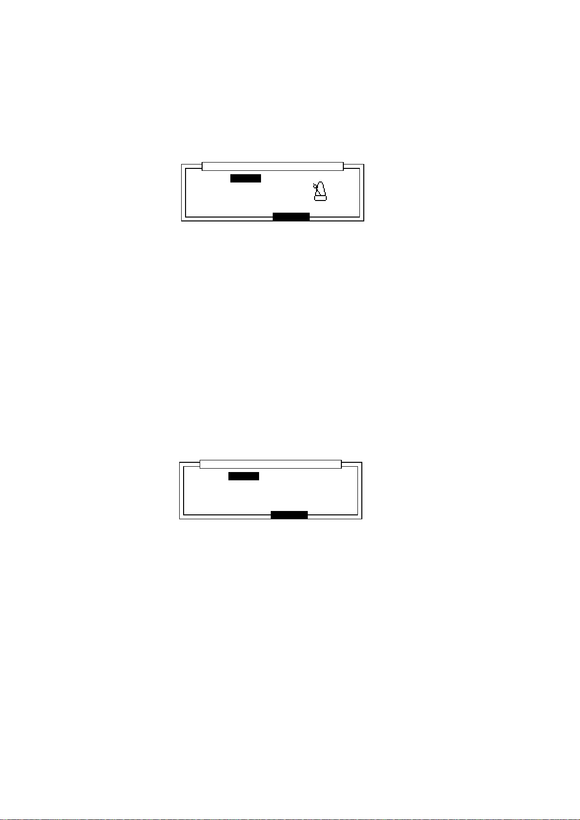
Chapter 3: Recording Sequences
Setting the metronome sound, volume and output
When the “Count/Metronome” window is displayed (see previous section), pressing “SOUND”
(F5) opens the “Metronome sound” window where you can select sounds and output for the
metronome.
....................................................................................
Sound: CLICK
Volume:100
Output:STEREO
........................
Metronome SoundMetronome Sound
CLOSE
............................
Sound:
Here you can select a metronome sound CLICK, DRUM 1, 2, 3 or 4.
By selecting DRUM 1-4, the metronome function can be used using the internal drum sounds.
If CLICK is selected, the following will be displayed.
Volume:
This sets the volume level of the metronome.
Output:
This sets where the sound of the metronome will be output from:
STEREO, from the STEREO OUT/HEADPHONE jacks.
OUT 1 – 8, from the optional ASSIGNABLE MIX OUT jacks.
If you select DRUM1, 2, 3 or 4 in the Sound: field, you can select 2 drum sounds (Accent
and Normal) that will play as the metronome sound. You can select the sounds by pressing one
of the drum pads or selecting the sound in the corresponding field.
The velocity level of the sounds can be adjusted in the Velocity: fields.
....................................................................................
Sound: DRUM4
Accent:37/A01 :127
Normal:37/A01 : 64
........................
Metronome SoundMetronome Sound
Velocty
CLOSE
............................
Page 46
Page 58

Chapter 3: Recording Sequences
Selecting a Track
Sq:01-Sequence01
.......................................................
™:120.0(MAS) Timing:1/16 Tsig: 4/ 4Tsig: 4/ 4
Count:OFF Loop: ONLoop: ON Bars: 0Bars: 0
..................................................................................................
Tr:01-Track-01 ON:YES Pgm:OFF
S:MIDI :10A-Device10 S:MIDI :10A-Device10 Velo%:100
STEP EDIT Tr -
TrMUTE SOLO Tr +
Now:001.01.00
Move the cursor to the Tr: field and select the track by rotating the DATA wheel. The name and
number of each track will appear.
Renaming a Track
To open the Track window, select the Tr: field and press the OPEN WINDOW key.
......................................................................................................
Track name:Track name:Track-01
....................................................................................
Default:Track-01
........................
........................................................................................................
Track name:
•
This changes the name of the track.
The name window will be displayed by turning the DATA wheel or tapping a pad.
Track
CLOSE COPYDELETE
............................
Press ENTER to save the name.
Note: If you do not press the ENTER key and move the
Default
field or other pages with
the CURSOR DOWN key, the entered name will be ignored and the name will not be
changed.
Default:
•
You can use this as the default name for each track (instead of Track). Enter the name in the
same way as the Track name.
Page 47
Page 59

Chapter 3: Recording Sequences
Deleting a Track
From the Main Screen, select the Tr: field and press OPEN WINDOW.
To open the Delete Track window, press DELETE [F2].
....................................................................................
Tr:01-Track-01
Pressing DO IT will erasePressing DO IT will erase
this track !!this track !!
........................
........................................................................................
Delete trackDelete track
CANCEL DO ITALL Tr
............................
To erase the data of the selected track, press DO IT [F5].
When you press ALL Tr [F3], the following warning will appear and all track data will be erased
when DO IT [F5] is pressed.
....................................................................................
........................
........................................................................................
Delete ALL TracksDelete ALL Tracks
Pressing DO IT WillPressing DO IT Will
erase ALL track data!!erase ALL track data!!
CANCEL DO IT
............................
Copying a Track
From the Main Screen, select the Tr: field and press OPEN WINDOW.
To open the Copy Track window, press COPY [F5].
....................................................................................
Tr:01-Track-01
Tr:01-Track-01
........................
........................................................................................
Copy Track
Copy
CANCEL DO IT
............................
Select the upper field by pressing the CURSOR UP key and select the track you want to copy with
the DATA wheel.
Select the lower field by pressing the CURSOR DOWN key and select the track that you want to
copy the data to with the the DATA wheel.
CAUTION: If there is data in the track that you have selected as the destination track, that
data will be erased and replaced with the new track.
To copy the data, press DO IT [F5].
Page 48
Page 60

Chapter 3: Recording Sequences
Turning the Track ON or OFF
Press the TrMUTE [F3] key to turn the track on (YES) or off (NO) (the present condition is
displayed in the On: field). It can also be turned off by moving the cursor to this field and rotating
the DATA wheel.
Sq:01-Sequence01
.......................................................
™:120.0(MAS) Timing:1/16 Tsig: 4/ 4Tsig: 4/ 4
Count:OFF Loop: ONLoop: ON Bars: 0Bars: 0
..................................................................................................
Tr:01-Track-01 ON:YES Pgm:OFF
S:DRUM1:OFF New Pgm-A S:DRUM1:OFF New Pgm-A Velo%:100
STEP EDIT Tr -
TrMUTE SOLO Tr +
Now:001.01.00
Turning tracks on or off with the drum pads
From the MAIN SCREEN, press TRACK MUTE, the indicator lights and the following screen will
appear.
Sq:01-Sequence01
.......................................................
Tr: (Unused) (Unused) (Unused) (Unused)
01-16 (Unused) (Unused) (Unused) (Unused)
(Unused) (Unused) (Unused) (Unused)
BANK
(Unused) (Unused) (Unused) (Unused)
A
Press pads to Track ON/OFFPress pads to Track ON/OFF
You can mute tracks by selecting one of the PAD BANKS: A (tracks 1-16), B (tracks 17-32), C
(tracks 33-48), D (tracks 49-64) and pressing the corresponding drum pad (pressing the pad again
turns the track back on).
The screen above shows all 16 tracks are turned on. When a track is turned off, the surrounding
blue field will disappear and the track name will be blue.
Now:001.01.00
SOLO
Sq:01-Sequence01
.......................................................
Tr: (Unused) (Unused) (Unused) (Unused)
01-16 (Unused) (Unused) (Unused) (Unused)
(Unused) (Unused) (Unused) (Unused)
BANK
(Unused) (Unused) (Unused) (Unused)
A
Press pads to Track ON/OFFPress pads to Track ON/OFF
Now:001.01.00
SOLO
By holding the SOLO [F6] key down and pressing one of the drum pads, you can solo a track so
that only that track will be turned on.
Press SOLO [F6] again to cancel the solo mode.
Sq:01-Sequence01
.......................................................
Tr: (Unused) (Unused) (Unused) (Unused)
01-16 (Unused) (Unused) (Unused) (Unused)
(Unused) (Unused) (Unused) (Unused)
BANK
(Unused) (Unused) (Unused) (Unused)
A
SOLO is activeSOLO is active
Now:001.01.00
SOLO
Press the TRACK MUTE key again return to the Main Screen.
Page 49
Page 61

Chapter 3: Recording Sequences
Deleting All the Tracks that You Have Turned Off
To delete all of the tracks that have been turned off, move the cursor to the Main Screen ON:
field.
Sq:01-BEAT
.......................................................
™:106.9(SEQ) Timing:1/16 Tsig: 4/ 4Tsig: 4/ 4
Count: ON Count: ON Loop: ONLoop: ON Bars: 2Bars: 2
..................................................................................................
Tr:05-ORCHESTRA_HIT ON: NO Pgm:56
S:MIDI : 2B-SG01k S:MIDI : 2B-SG01kVelo%:100
STEP EDIT Tr -
TrMUTE SOLO Tr +
Now:001.01.00
Press OPEN WINDOW to display the Erase all OFF tracks screen.
......................................................................................................
........................
........................................................................................................
Erase all OFF tracksErase all OFF tracks
Pressing DO IT will erasePressing DO IT will erase
all OFF tracks!!all OFF tracks!!
CLOSE DO IT
............................
Press DO IT [F5] to delete all the off tracks and return to the Main Screen.
Setting the Track Type
This sets the track to either the sound source within MPC2000XL or other external MIDI devices.
Sq:01-Sequence01
.......................................................
™:120.0(MAS) Timing:1/16 Tsig: 4/ 4Tsig: 4/ 4
Count:OFF Loop: ONLoop: ON Bars: 0Bars: 0
..................................................................................................
Tr:01-Track-01 ON:YES Pgm:OFF
S:MIDI :10A-Device10 Velo%:100
STEP EDIT Tr -
TrMUTE SOLO Tr +
Now:001.01.00
Select the field as shown above with the CURSOR keys and select between MIDI and Drum
1 – 4 by rotating the DATA wheel.
MIDI Allows data input from devices such as MIDI keyboards and uses the
track to play the sound source of external MIDI devices.
Drum 1 – 4 Allows data input from DRUMS PAD and uses the track to play the inter-
nal sound source.
Because programs can be assigned individually to DRUM 1-4, the tracks
can be assigned to different drum programs and up to 4 different programs can be played at the same time.
Page 50
Page 62

Chapter 3: Recording Sequences
Settings for MIDI Reception
From the Main Screen, select the track type field (MIDI or Drum 1-4) and press the OPEN WINDOW key to display the MIDI input window.
......................................................................................................
Receive channel:Receive channel:ALL Prog change>seq:OFFProg change>seq:OFF
Sustain pedal to Duration: ONSustain pedal to Duration: ON
....................................................................................
MIDI filter:OFFMIDI filter:OFF
Type:NOTES Pass?:YES
........................
........................................................................................................
Receive channel:
•
MIDI InputMIDI Input
CLOSEMONITR
............................
Set the receiving MIDI channel. All the other data that has not been set to a MIDI channel
is ignored. Set this to ALL to receive on all MIDI channels.
Prog change 4 Seq:
•
You can set whether sequences are changed with MIDI Program Change messages from
an external MIDI device. When set to ON, Program Change messages will be received and
the same sequence number as the MIDI Program Change number will be selected.
Sustain Pedal to Duration:
•
When performances from devices such as a MIDI keyboard are recorded to the sequencer,
the sustain pedal message (control number 64) is recorded with the note data, but the
following issues arise.
1. If you delete or erase a section of the sequence that contained a Sustain Off message, all notes after that location will be sustained until the next Sustain On message.
2. When multiple tracks are set to the same MIDI channel and one track only contains
sustain pedal data, the other track(s) set to the same MIDI channel will also have
sustain effects.
3. If you merge a track with sustain pedal information into a track without sustain pedal
information, notes on the resultant track will be sustained.
4. If you overdub notes into a track containing sustain pedal information, the new notes
will be sustained.
The MPC2000XL solves these problems by specially processing sustain pedal messages. If the
Sustain pedal to Duration field is set to ON, when the MPC2000XL receives a
Sustain On message during record, it will NOT record it. Instead, it will be converted to Note ON/
OFF data. As a result, the duration of the note on the recorded track becomes longer.
There are some situations in which converting sustain pedal to the duration of the note is undesirable:
1. Depending on the settings and specifications of the MIDI sound source when the
duration of a note is too long and exceeds the number of voices that can be sounded,
new notes may be ignored and may not generate a sound.
2. Depending on the settings of the MIDI sound source, MIDI control number 64 may be
used for messages other than sustain.
In this case, by turning this field off, you can record a sustain pedal message (control number 64).
Page 51
Page 63

Chapter 3: Recording Sequences
MIDI Filter Function
This sets the MPC2000XL to receive or not receive MIDI events.
MIDI filter:
•
This is the on or off setting for the entire MIDI filter function. When this is off, all MIDI events
will be received regardless of the settings in the Type: and Pass?: fields.
Type:
•
Set the type of MIDI event - the following MIDI events can be filtered (for details on MIDI
events, it is advisable to read a MIDI guide book).
NOTES, PITCH BEND, PROG(ram) CHANGE, CH(annel) PRESSURE, POLY
PRESS(ure), EXCLUSIVE, CONTROL:ALL (All control changes, Control Change
#000 ~ #127).
Pass?:
•
This sets the reception of a MIDI event selected in Type:. Set this to YES to receive MIDI
events set in Type: and NO to ignore the events.
Pressing MONITR [F2] displays the MIDI input monitor , where you can monitor which MIDI channels are being received (the black squares above the MIDI channel numbers will flash).
......................................................................................................
....................................................................................
........................
........................................................................................................
MIDI Input MonitorMIDI Input Monitor
CLOSE
Setting the Track’s MIDI Channel
This sets the MIDI output channel of the selected track.
Sq:01-(Sequence01)
.......................................................
™:120.0(MAS) Timing:1/16 Tsig: 4/ 4Tsig: 4/ 4
Count:OFF Loop: ONLoop: ON Bars: 0Bars: 0
..................................................................................................
Tr:01-Track-01 ON:YES Pgm:OFF
S:MIDI : S:MIDI :10A-Device10 Velo%:100
STEP EDIT Tr -
TrMUTE SOLO Tr +
Select the field as shown above with the CURSOR keys and rotate the DATA wheel to select the
MIDI output channel.
For example, in the setting shown above, the data of track 01 (which is currently selected) sends
data from MIDI OUT A on MIDI channel 10.
Now:001.01.00
Set the MIDI channel to correspond to the connected MIDI sound source. For example, if the MIDI
channel of the external MIDI sound source you want to play is set to 5, you can use track data to
play the MIDI sound source by setting the MIDI channel of the track to 5. The drum tracks are
normally used to play the internal sampler, but if a MIDI channel is set it will output MIDI data from
the selected channel. If you do not want to output the drum track data in MIDI format, set the MIDI
channel to OFF.
Page 52
Page 64

Chapter 3: Recording Sequences
Settings for MIDI output
To display the MIDI output window, from the Main Screen, select the field shown below.
Sq:01-(Sequence01)
.......................................................
™:120.0(MAS) Timing:1/16 Tsig: 4/ 4Tsig: 4/ 4
Count:OFF Loop: ONLoop: ON Bars: 0Bars: 0
..................................................................................................
Tr:01-Track-01 ON:YES Pgm:OFF
S:MIDI : S:MIDI :10A-Device10 Velo%:100
STEP EDIT Tr -
TrMUTE SOLO Tr +
Now:001.01.00
Then press OPEN WINDOW.
......................................................................................................
Soft thru:AS TRACKSoft thru:AS TRACK
....................................................................................
Device name:10A-Device10Device name:10A-Device10
........................
........................................................................................................
MIDI OutputMIDI Output
CLOSE PANICMONITR
............................
Soft thru:
To set the MIDI channel that MIDI data received at MIDI IN is to be sent out through MIDI OUT.
OFF
MIDI through is turned off.
AS TRACK
In single track recording mode, the MIDI OUT channel will be set according to the setting
of each track.
In multiple track recording mode, the MIDI OUT signal will be sent out as specified in the
Multi Recording Setup window.
OMNI-A
MIDI data received at MIDI IN will be sent out through MIDI OUT A.
During track playback, this data will be merged with the track data.
OMNI-B
MIDI data received at MIDI IN will be sent out through MIDI OUT B.
OMNI-AB
MIDI data received at MIDI IN will be sent out through MIDI OUT A and B.
Device name:
You can name a MIDI device name here after selecting the MIDI channel (01A - 16B). This
setting is common to all sequences.
Panic
This will stop all external MIDI devices from playing (All note off and Reset all controller
messages are sent).
Pressing MONITR [F2] displays the MIDI output monitor, where you can monitor which MIDI
channels are being sent (the black squares above the MIDI channel numbers will flash).
......................................................................................................
OUT A
....................................................................................
OUT B
........................
........................................................................................................
MIDI Output MonitorMIDI Output Monitor
CLOSE
Page 53
Page 65

Chapter 3: Recording Sequences
Multiple Track Recording
With this mode, multiple tracks can be recorded at the same time.
From the Main Screen (press MAIN SCREEN), move the cursor to the S: field.
Sq:01-(Sequence01)
.......................................................
™:120.0(MAS) Timing:1/16 Tsig: 4/ 4Tsig: 4/ 4
Count:OFF Loop: ONLoop: ON Bars: 2Bars: 2
..................................................................................................
Tr:01-Track-01 ON:YES Pgm:OFF
S:MIDI :10A-Device10:MIDI :10A-Device10 Velo%:100
STEP EDIT Tr -
TrMUTE SOLO Tr +
Now:001.01.00
Here you can select S for single track recording or M for multiple track recording.
In single track recording mode, only the track currently selected in the Main Screen will be recorded. In the multiple track recording mode, a number of tracks can be recorded simultaneously .
If you selected multiple track recording, press OPEN WINDOW to display the Multi Re-
cording Setup screen.
......................................................................................................
....................................................................................
........................
........................................................................................................
Multi Recording Setup
CLOSE
...........................
In (MIDI channel input)
Select the MIDI input channel with the CURSOR UP/DOWN keys.
Track
Select the track to be recorded to. If two or more of the MIDI inputs are set to the same track,
MIDI data will be merged onto that track and recorded. Set the Track field to OFF if you do
not want to record.
Out (MIDI channel output)
Select the track with the CURSOR UP/DOWN keys and enter the MIDI output channel with the
DATA wheel. If two or more of the MIDI inputs are set to the same track, they will be merged
and sent out.
To start recording, close the window and then hold REC and press PLAY.
Page 54
Page 66
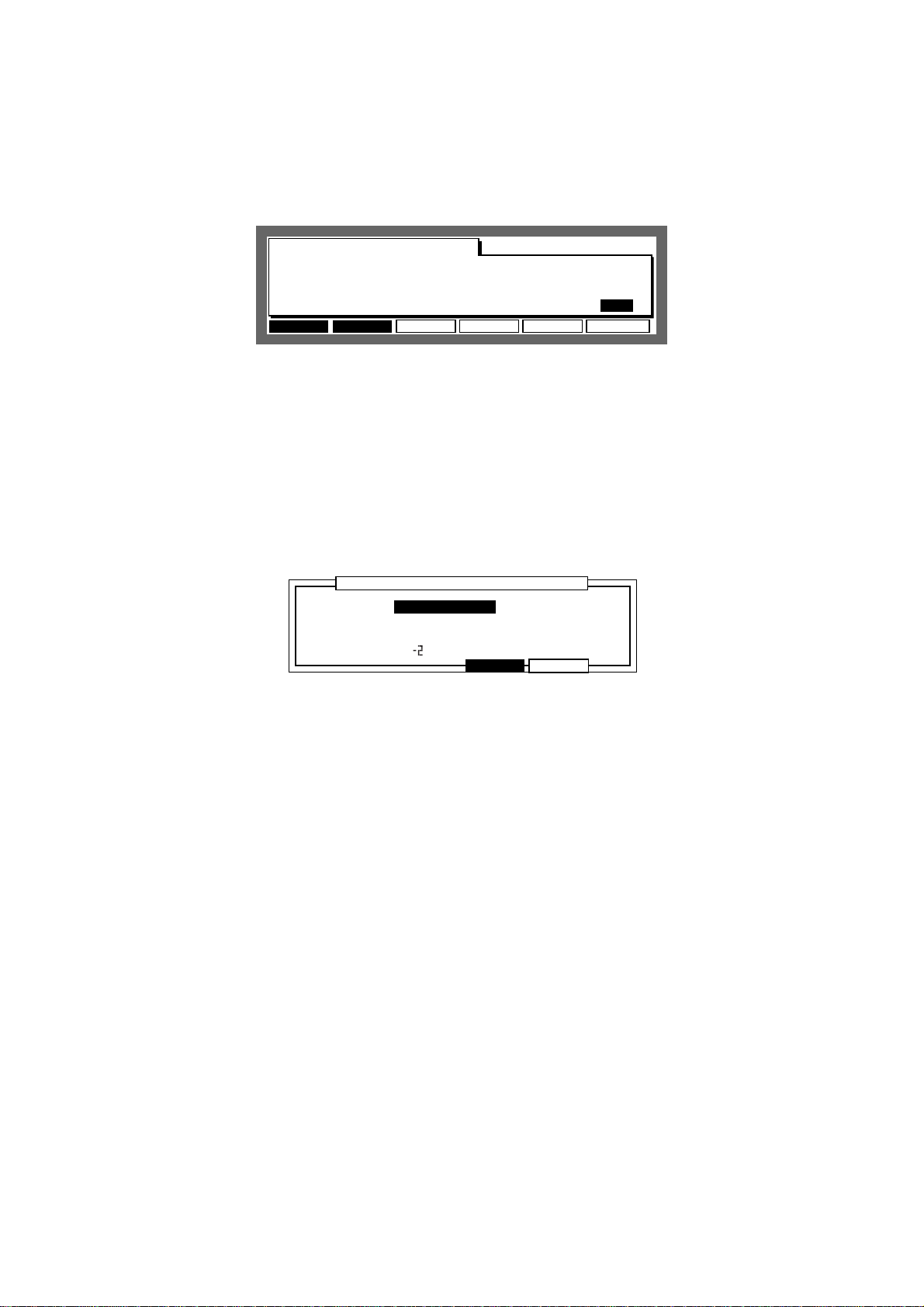
Chapter 3: Recording Sequences
Editing the Velocity
This adjusts the velocity of the data that is recorded on the selected track when the sequence is
played.
Sq:01-(Sequence01)
.......................................................
™:120.0(MAS) Timing:1/16 Tsig: 4/ 4Tsig: 4/ 4
Count:OFF Loop: ONLoop: ON Bars: 2Bars: 2
..................................................................................................
Tr:01-Track-01 ON:YES Pgm:OFF
S:MIDI :10A-Device10 S:MIDI :10A-Device10 Velo%:100
STEP EDIT Tr -
TrMUTE SOLO Tr +
Now:001.01.00
Select the Velo%: field with the CURSOR keys and set the incremental or decremental ratio of
the velocity with the DATA wheel.
CAUTION: This setting will not directly edit the recorded data. The velocity will increase or
decrease according to the ratio set here only during playback. Also, data with a
maximum velocity (127) will not be affected by values set over 100%.
To edit the velocity of prerecorded data, use the Edit Velocity window.
To display the Edit Velocity window, select the Velo%: field and press OPEN WINDOW.
......................................................................................................
Edit type:Edit type:ADD VALUEADD VALUE Value: 1Value: 1
....................................................................................
Time:001.01.00-001.01.00
Notes: 0 (C. )-127(G.8)Notes: 0 (C. )-127(G.8)
........................
........................................................................................................
Edit VelocityEdit Velocity
CLOSE DO IT
............................
To directly change the velocity of recorded data, set the following fields and press DO IT[F5].
Edit type:
•
Select the method of changing the velocity.
ADD VALUE Adds the set Value: to the current velocity.
SUB VALUE Subtracts the set Value: from the current velocity.
MULT VAL% Increases or decreases the set Value: ratio (percentage) against the
current velocity.
SET TO VAL Sets all of the velocity values uniformly to the set Value:.
Value:
•
Sets the value of the edit method selected in Edit type:.
Time:
•
Specifies the data range to be edited when the velocity of the recorded data is edited. Any
data not specified within this range will not be edited.
• Notes:
Specifies the note range to be edited on the MIDI track when the velocity of recorded data
is edited. Any note not specified within this range will not be edited. On the Drum track,
notes can be entered by pressing the drum pads.
Page 55
Page 67

Chapter 3: Recording Sequences
Setting the Program Change Transfer
You can send program changes on each track in addition to sending program change events
within a track when a sequence is selected.
Sq:01-(Sequence01)
.......................................................
™:120.0(MAS) Timing:1/16 Tsig: 4/ 4Tsig: 4/ 4
Count:OFF Loop: ONLoop: ON Bars: 2Bars: 2
..................................................................................................
Tr:01-Track-01 ON:YES Pgm:OFF
S:MIDI :10A-Device10 S:MIDI :10A-Device10 Velo%:100
STEP EDIT Tr -
TrMUTE SOLO Tr +
Now:001.01.00
Select the Pgm: field with the CURSOR key and set the program number you want to set with the
data wheel. The program change will not be sent if set to OFF.
To display the following window, select the Pgm: field and press OPEN WINDOW.
......................................................................................................
Transmit program changesTransmit program changes
in this track:in this track:YES
........................
........................................................................................................
Program changeProgram change
CLOSE
............................
Set the field to enable (YES) or disable (NO) the transfer of program change recorded on the
selected track. When this is set OFF, the program change will not be sent even if there is a
program change on the track.
Locating with the DATA Wheel
You can locate a point in the sequence with the DATA wheel.
Sq:01-(Sequence01)
.......................................................
™:120.0(MAS) Timing:1/16 Tsig: 4/ 4Tsig: 4/ 4
Count:OFF Loop: ONLoop: ON Bars: 2Bars: 2
..................................................................................................
Tr:01-Track-01 ON:YES Pgm:OFF
S:MIDI :10A-Device10 S:MIDI :10A-Device10 Velo%:100
STEP EDIT Tr -
TrMUTE SOLO Tr +
To locate, select the Now: field with the CURSOR keys and increase or decrease the number
with the DATA wheel.
Units Used to Locate a Point
You can select bar/beat/clock or hours/minutes/seconds to be displayed in the Now: field.
Select the Now: field and press OPEN WINDOW.
......................................................................................................
Display style:BAR,BEAT,CLOCK
start time:00h00m00s00f00
Frame rate:25
........................
........................................................................................................
Time DisplayTime Display
CLOSE
Now:001.01.00
............................
Page 56
Page 68

Chapter 3: Recording Sequences
Display style:
•
Select BAR,BEAT,CLOCK to display bar, beat, and clock. Select
HOUR,MINUTE,SEC to display the hours, minutes, and seconds.
Start time:
•
Select HOUR,MINUTE,SEC in Display style: to start the time display on the
main screen from the time set in this field. This can also be used as the start time to
synchronize MTC (MIDI time code) or SMPTE time codes.
Frame rate:
•
This sets the frame rate of the time code used to synchronize the MTC or SMPTE code.
Synchronization is described in “MIDI/SYNC Mode”.
The Main Screen Function Keys
Sq:01-(Sequence01)
.......................................................
™:120.0(MAS) Timing:1/16 Tsig: 4/ 4Tsig: 4/ 4
Count:OFF Loop:OFF Bars: 2Bars: 2
..................................................................................................
Tr:01-(Unused) ON:YES Pgm:OFF
S:DRUM1:OFF New Pgm-A New Pgm-A Velo%:100
STEP EDIT Tr -
TrMUTE SOLO Tr +
Now:001.01.00
•
This displays the step edit page which allows you to edit on sequence data at a time.
•
This edits or sets other elements of a sequence.
TrMUTETrMUTE
TrMUTE
TrMUTETrMUTE
TrMUE
•
This turns the track on or off.
•
This enables you to play only the currently selected track. The SOLO display blinks when
you press the key and enables solo playing. Press it again to turn it OFF, enabling all tracks
to play.
•
Select the track with this function key. It is not necessary to move the cursor to the Tr:
field.
Page 57
Page 69

Chapter 3: Recording Sequences
The Play/Record Keys and the Locate Keys
These ten keys operate similarly to the transport keys on a tape recorder, with some useful additions:
The PLAY START key:
•
This plays back the currently selected sequence to begin playing from the first bar.
The PLAY key:
•
This plays back the sequence from the current position displayed in the Now: field on the
Main Screen.
The STOP key:
•
This stops playback or recording.
The OVERDUB key:
•
While holding this key, press PLAY to overdub new notes to the track, without erasing
existing notes. You can Overdub from the stop or playback modes.
While the Overdub mode is active, the light above the OVERDUB key is on.
To cancel the Overdub mode, press the OVERDUB key again and the light above the key
will turn off.
The REC key:
•
While holding this key, press PLAY to start recording. New notes can be recorded into the
currently selected track while existing notes are erased, just as with a tape recorder.
You can record from the stop or playback modes.
During recording, the LED above the REC key is on.
To stop recording, press the RECORD key again and the light above the key will turn off.
The BAR << / >> Keys:
•
By pressing one of these keys, you can move the sequence position back or forward by one
bar. To move to the beginning of the sequence, hold down the GO TO key and press the
BAR << key. To move to the end of the sequence, hold down the GO TO key and press the
BAR >> key.
The STEP < / > Keys:
•
By pressing one of these keys, you can move the sequence position back or forth by setting
a number on the Timing: field on the Main Screen. For example, when the Timing is set
to 1/16, you can move back 24 ticks every time you press STEP >. If you press this button
while holding down the GO TO key, you can locate the position directly before or after an
entered event.
The GO TO Key:
•
This key is used to move to a specific position within the sequence. When pressed, the
following screen is displayed:
......................................................................................................
...................................................................................................
7:001.01.00 8:001.01.00 9:001.01.007:001.01.00 8:001.01.00 9:001.01.00
4:001.01.00 5:001.01.00 6:001.01.004:001.01.00 5:001.01.00 6:001.01.00
1:001.01.00 2:001.01.00 3:001.01.001:001.01.00 2:001.01.00 3:001.01.00
........................
Go to:
When the window is opened, the time from the Now: display of the Main Screen is
displayed here.
You can change the displayed time with the DATA wheel or input it directly with the
numeric keys and then press GO TO to move to that location and return to the Main
Screen.
Locate
Go to:Go to:001.01.00
CLOSE GO TOSTORE
............................
Page 58
Page 70

Chapter 3: Recording Sequences
Storing a locate point from the stop mode
Select a location point in the Now: field of the Main Screen and press the GO TO key.
Select a locate memory (that you want to save) from 1 - 9 with the CURSOR keys.
......................................................................................................
...................................................................................................
7:001.01.00 8:001.01.00 9:001.01.007:001.01.00 8:001.01.00 9:001.01.00
4:001.01.00 5:001.01.00 6:001.01.004:001.01.00 5:001.01.00 6:001.01.00
1:001.01.00 2:001.01.00 3:001.01.00 2:001.01.00 3:001.01.00
........................
Locate
Go to:001.01.00Go to:001.01.00
CLOSE GO TOSTORE
............................
Press STORE [F2], the locate point is stored and the Main Screen will re-appear.
Moving to stored locate points
Press the GO TO key and select from locations 1 - 9 with the CURSOR keys. Then press GO TO
[F5] to move to the selected location.
Page 59
Page 71

Chapter 3: Recording Sequences
AUTO PUNCH IN / OUT
Auto Punch allows you to Overdub or Record automatically between 2 preset points. This can be
very useful at times such as when you want to execute a very tight punch-in and there isn’t enough
time to get from the MPC2000XL to the MIDI keyboard to play the new notes after the punch-in.
The Auto Punch function allows you to punch in automatically, allowing you to concentrate on your
performance.
Hold SHIFT and press MISC. (2 on the numeric pad).
Auto punch:
•
Auto punch:Auto punch:PUNCH IN ONLYPUNCH IN ONLY
IN
Time:001.01.00
TurnONPUNCH TRANS 2ndSEQ
There are three auto punch modes:
PUNCH IN ONLY This allows you to automatically punch in only. To stop the
recording, press STOP.
PUNCH OUT ONLY This allows you to automatically punch out only. To start
recording, press PLAY or PLAY START while holding down
REC or OVER DUB.
PUNCH IN OUT Both punch-in and punch-out are executed automatically.
IN
•
Sets the auto punch in point.
OUT
•
Sets the auto punch out point.
To start auto punch, press TurnON [F6]. The display returns to the Main Screen and is now in
standby mode.
Sq:01-(Sequence01)
.......................................................
™:120.0(MAS) Timing:1/16 Tsig: 4/ 4Tsig: 4/ 4
Count:OFF Loop:OFF Bars: 2Bars: 2
..................................................................................................
Tr:01-(Unused) ON:YES Pgm:OFF
S:DRUM1:OFF New Pgm-A New Pgm-A Velo%:100
Auto punch function is active!!Auto punch function is active!!
Now:001.01.00
OFF
While holding REC or OVERDUB, press PLAY or PLAY START to start recording.
Punch in or out will automatically start at the set point and enable you to record your performance.
To cancel auto punch, press OFF [F6] and return to the normal Main Screen.
Page 60
Page 72

Chapter 4: Editing Sequences
Chapter 4
Editing Sequences
Page 61
Page 73

Chapter 4: Editing Sequences
Overview
There are three ways to edit a sequence. The first is to erase unnecessary note data using the
ERASE key. The second is to display and edit each note or event. The third is to specify the bar
or note range and edit the data together.
Erasing Data with the ERASE Key
To erase data with the ERASE key, you play back a sequence and erase a random note, or
display the note or event and erase them individually.
Erasing a Note in Real Time
It is possible to erase random note data while you are playing back a sequence in Overdub mode.
1 Select the track with the data you want to erase on the Main Screen.
2 Either press PLAY or PLAY START while holding OVER DUB or press OVERDUB during
playback to switch to Overdub mode.
3 Locate the data you want to erase, and while holding ERASE, press the drum pad as-
signed to the sound.
Besides erasing the drum track, you can erase notes by continuously pressing the note on the
MIDI keyboard while holding ERASE.
Using the ERASE Window to Erase Data
When a sequence is not playing, press ERASE to display the ERASE window. You can select and
erase specific notes or data sections.
......................................................................................................
Track: 1-Track-01 (0=a11)
Time:001.01.00-001-01-00
Erase:ALL EVENTSErase:ALL EVENTS
Notes:ALL (Hit pad)
........................
.........................................................................................................
Track:
•
This specifies the track that you want to erase. If you set this to 0, it will mean that all tracks
are selected.
ERASE
CANCEL DO IT
............................
Time:
•
This sets the range that you want to erase.
• Erase:
Select from the following three event types to erase:
ALL EVENTS This erases all the events within the range selected in the
Time: field. For note events, only the notes set in the Note:
field below are erased.
Page 62
Page 74

Chapter 4: Editing Sequences
ALL EXCEPT This erases all events except those selected. When ALL EX-
CEPT is selected, the field on the right enables you to select the
event. The events selected here will not be erased. For note
events, the notes set in the Note: field below are erased.
When notes are selected in the field where events are selected,
the Note: field will not appear and all the data except the notes
will be erased.
ONLY ERASE This erases only the selected events. When ONLY ERASE is
selected, the field on the right enables you to select an event.
Only the event selected here will be erased. The Note: field
will appear only when NOTES is selected in the event selection
field. When NOTES is selected, only the notes set here are
erased.
Notes:
•
This sets the notes that you want to erase.
Note: Depending on whether the track selected in the
MIDI track, the
Notes:
field display will change as follows:
Drum track
......................................................................................................
Track: 1-Track-01 (0=all)
Time:001.01.00-001.01.00
Erase:ALL EVENTSErase:ALL EVENTS
Notes:60/C05 (Hit pad)
........................
.........................................................................................................
ERASE
CANCEL DO IT
MIDI track
......................................................................................................
Track: 1-Track-01 (0=all)
Time:001.01.00-001.01.00
Erase:ALL EVENTSErase:ALL EVENTS
Notes: 0 (C. )-127(G.8)
........................
.........................................................................................................
ERASE
CANCEL DO IT
Press DO IT [F5] to erase.
Track:
field is a drum track or
............................
............................
Page 63
Page 75

Chapter 4: Editing Sequences
Step Editing
The Step Edit screen allows you to finely edit MIDI data on a track or enter data one at a time from
the drum pads or a MIDI keyboard.
Step Editing Screen
From the Main Screen, press STEP [F1] to display the Step Edit screen.
View:ALL EVENTSALL EVENTS Now:001.01.00
..................................................................................................
>N: 38/A06 Tun: 0 D: 1 V:0 D: 1 V: 37
>N: 46/A07 Tun: 0 D: 2 V:0 D: 2 V: 26
>N: 46/A07 Tun: 0 D: 28 V:0 D: 28 V: 10
>N: 46/A07 Tun: 0 D: 1 V:0 D: 1 V: 11
DELETE INSERT PLAYTC PASTECOPY
View:
•
This specifies the type of events:
ALL EVENT Displays all of the events recorded on a track.
NOTES Displays only the notes. By selecting NOTES, the note range
setting field will also appear. The notes of the range specified
here will be displayed.
PITCH BEND Displays only the pitch bend data.
CTRL: Displays only the control change data. By selecting CTRL:, a
field to select the control change number will also appear. This
field will only display the control change event selected here.
When ALL is selected, all of the control change events will be
displayed.
PROG CHANGE Displays only the program change data.
CH PRESSURE Displays only the channel pressure data.
POLY PRESS Displays only the poly pressure data.
EXCLUSIVE Displays only the exclusive data.
Open the Step Edit Options window by selecting a field and pressing OPEN WINDOW.
....................................................................................
Auto step increment:Auto step increment:YES
Duration of recorded notes:Duration of recorded notes:
AS PLAYED
........................
........................................................................................
Auto step increment:
•
Step Edit OptionsStep Edit Options
CLOSE
............................
After entering data in step input, you can automatically move a sequence according to the
value set in the Timing: field on the main screen each time an event is entered from a
pad or MIDI keyboard.
Setting this to YES will move the sequence according to the settings in the Timing: field
after the drum pad or MIDI keyboard has been released (and the note off has been sent).
Duration of recorded notes:
•
During step input, this sets the duration of the entered note to either the length of time the
key is actually pressed or to a predetermined length.
Page 64
Page 76

Chapter 4: Editing Sequences
AS PLAYED The metronome will play from the moment the drum pad or MIDI key-
board is pressed until it is released.
TC VALUE: Regardless of the time that the key is actually pressed, the duration will
be the value set in the Timing: field.
When TC VALUE is selected, the percentage field will also appear.
The duration is set against the Timing: field by percentage. For example, if it is set to 50%, the duration is half the amount set in the Tim-
ing: field and the result will be a staccato sound.
Timing Correct in “Step Edit”
When the TC [F1] key is pressed, the following window will appear.
View:ALL EVENTS Now:001.01.00
..................................................................................................
>N: 38/A06 Tun: 0 D: 1 V:0 D: 1 V: 37
>N: 46/A07 Tun: 0 D: 2 V:0 D: 2 V: 26
>N: 46/A07 Tun: 0 D: 28 V:0 D: 28 V: 10
>N: 46/A07 Tun: 0 D: 1 V:0 D: 1 V: 11
.........................................
Value:1/16(3)
......
.............................................
DELETE INSERT PLAYTC PASTECOPY
.........
While pressing the key, rotate the DATA wheel to change the value of “Timing Correct”.
For more details, please refer to the “Timing Correct” section.
The Event Display
The note event displayed on the step edit screen will change depending on whether the selected
track is a drum track or a MIDI track.
Drum track
N: This is the note number and the Drum Pad number assigned to it.
Tun: This field will display the note variation data.
D: This is the duration (length of note on).
V: This is the velocity (how hard the note is played). The right side will display the
velocity value in a bar chart.
MIDI Track
N: This displays the note number and note name.
D: This is the duration (length of note on).
V: This is the velocity (how hard the note is played). The right side will display the
velocity value in a bar chart.
Bend
Control Change
Program Change
Page 65
Page 77

Chapter 4: Editing Sequences
Channel Pressure
Polyphonic Pressure
Exclusive Data
Exclusive:F0 F7Exclusive:F0 F7
Operating the List Display
When many events are entered at one point and the whole list cannot be displayed, you can scroll
through the list with the CURSOR UP or DOWN keys.
Press PLAY [F6] to generate the selected event.
Selecting and Editing Multiple Events
Multiple MIDI events on the display can be selected together by holding SHIFT and selecting the
events with the CURSOR UP or DOWN keys. In this case the parameters are displayed as white
characters on a blue background.
View:ALL EVENTSALL EVENTS Now:001.01.00
..................................................................................................
>N: 46/A07 Tun: 0 D: 2 V:0 D: 2 V: 26
>N: 46/A07 Tun: 0 D: 1 V:0 D: 1 V: 11
>N: 46/A07 Tun: 0 D: 28 V:0 D: 28 V: 10
DELETE EDIT PLAYTC COPY
When multiple events are selected, EDIT [F4] appears in place of the function keys INSERT
[F4] and PASTE [F5] as shown above.
By pressing EDIT [F4], the Edit Multiple window (corresponding to the field selected with the
cursor) will appear.
◆ When a note number is selected, all the selected notes are changed to the note number set
here. Select the note number with the DATA wheel and press DO IT [F5] to execute.
......................................................................................................
........................
.........................................................................................................
Edit MultipleEdit Multiple
Change note to:Change note to:46(A#1)
CANCEL DO ITDO IT
............................
◆ When parameters other than note numbers are selected, edit the value of the selected
parameter using the window shown below.
...................................................................................................
........................
......................................................................................................
Edit MultipleEdit Multiple
Edit type:ADD VALUE
Value:100
DO ITDO ITCANCEL
............................
Page 66
Page 78
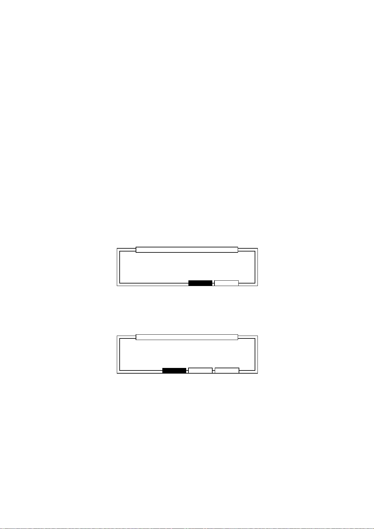
Chapter 4: Editing Sequences
Edit type:
•
Edit the selected parameters according to the following settings.
ADD VALUE This adds the value set in Value: to the current value.
SUB VALUE This subtracts the value set in Value: from the current value.
MULT VAL% This increases or decreases the current value by the percentage
set in Value:.
SET TO VAL This unifies all the parameters to the value set in Value:.
Value:
•
This sets the edit method selected in Edit type:.
Copying an Event
To temporarily save the data on the clip board, select an event and execute Copy.
To execute Copy, press COPY [F2] after selecting the event.
Deleting an Event
Press DELETE [F3] after selecting the event.
Pasting an Event
To paste data which was copied to the clip board, specify the point where you want to paste it in
the Now: field and press PASTE [F5].
......................................................................................................
Pressing DO IT will pastePressing DO IT will paste
events from clipboard.events from clipboard.
........................
.........................................................................................................
Press DO IT[F5] to execute the paste.
If multiple data with time ranges are saved to the clip board, the following screen will appear when
you press PASTE [F5].
......................................................................................................
RPLACE:pasted events willRPLACE:pasted events will
replace existing events.replace existing events.
MERGE:pasted events willMERGE:pasted events will
merge with existing events.merge with existing events.
........................
.........................................................................................................
Press RPLACE [F4] to erase the data in the specified point and overwrite with the contents of the
clip board.
Paste EventPaste Event
CANCEL DO IT
Paste EventPaste Event
CANCEL RPLACE MERGE
............................
............................
Press MERGE [F5] to merge the data with existing data.
Page 67
Page 79

Chapter 4: Editing Sequences
Inserting an Event
To insert an event, specify the point of insertion in the Now: field and press INSERT[F4].
....................................................................................
Type: NOTE
........................
........................................................................................
Insert EventInsert Event
DO ITCANCEL
............................
Select the type of event you want to insert from the following:
NOTE, PITCH BEND, CONTROL CHANGE, PROGRAM CHANGE, CH PRESSURE,
POLY PRESSURE, EXCLUSIVE and MIXER.
When EXCLUSIVE is selected, a field displaying the byte volume of the exclusive message to be
entered appears. Set the volume (byte) of the exclusive message you want to enter.
By pressing DO IT [F5], you can return to the step edit screen. Since the event set in the Insert
Event window will be inserted, set the parameter with the CURSOR keys and DATA wheel.
It is also possible to insert a note directly from a drum pad or keyboard. For details, refer to the
following “Step Recording.”
Step Recording
On the step edit page displayed by pressing STEP [F1] on the main screen, it is possible to use
the drum pad or a MIDI keyboard to step record.
View:ALL EVENTSALL EVENTS Now:001.01.00
..................................................................................................
>N: 38/A06 Tun: 0 D: 1 V:0 D: 1 V: 37
>N: 46/A07 Tun: 0 D: 2 V:0 D: 2 V: 26
>N: 46/A07 Tun: 0 D: 28 V:0 D: 28 V: 10
>N: 46/A07 Tun: 0 D: 1 V:0 D: 1 V: 11
DELETE INSERT PLAYTC PASTECOPY
Set the point where you want to enter a note in the Now: field and enter the note with a drum pad
or MIDI keyboard connected to MIDI IN. In doing so, the velocity (the strength of the note on) or
the duration (length of the note) is affected by the entered data.
When Auto Step Increment: in the Step Edit Options window (see page 64) is set to
YES, during step recording, the Now: field points increase by the amount set in the Timing:
field of the Main Screen each time a note is entered.
Page 68
Page 80

Chapter 4: Editing Sequences
The Editing Screen
The editing screen allows you to copy an entire event within a sequence. It is also possible to
rearrange the tracks, transpose, or set the preferences of a newly created sequence.
To display the editing screen, press EDIT [F2] in the main screen.
Event edit
Time and notes are specified here for various types of editing.
Copying an Event
When Copy is selected in the Edit: field the following screen is displayed.
Edit:COPY
.................................
Time:
001.001.00-001.01.00
Notes:
ALL
EVENTS BARS
Here you can copy all of the events recorded in a sequence, but it is necessary to set a pad for the
drum track and a note range for the MIDI track.
◆ Left Window
Time:
•
Set the range of the event you want to copy.
Notes:
•
Set the note of the copy source. A pad number will appear if the track is a drum track, and
a note range will appear if the track is a MIDI track. You can directly set the copy source
from a drum pad or MIDI keyboard.
◆ Right Window
From sq/Tr:
•
Select the sequence or track that you want to copy. Here, only the number will appear.
To sq/Tr:
•
This selects the sequence or track that you want to copy to. Here, only the number will
appear.
Mode:
•
This selects whether you will be writing over the existing data (REPLACE) or mixing the
data (MERGE). When REPLACE is selected, the event in the copy destination is erased
and is replaced with the copy source data. When MERGE is selected, the copy destination
data and the copy source data is mixed.
TrMOVE USER
From sq:80 Tr: 1From sq:80 Tr: 1
To sq:80 Tr: 1To sq:80 Tr: 1
Mode:REPLACE
Start:001.01.00
Copies: 1Copies: 1
DO IT
Start:
•
This specifies the point where you want to start copying. The copy source data will be
pasted at the point set here for the number of times set in Copies: (below).
Copies:
•
This specifies the number of copies. From the point set in Start:, the data will be
pasted the number of times set here.
To execute the copy, press DO IT[F6].
Page 69
Page 81

Chapter 4: Editing Sequences
Editing the Duration of a Note
When DURATION is selected in the Edit: field the following screen is displayed.
Edit:DURATION
.................................
Time:
001.001.00-001.01.00
Notes:
ALL
EVENTS BARS
TrMOVE USER
Edit sq: 1 Tr: 1
Mode:ADD VALUE
Value: 1
DO IT
◆ Left Window
Time:
•
Set the range of the event you want to edit.
Notes:
•
Set the note you want to edit. A pad number will appear if the track is a drum track, and a
note range will appear if the track is a MIDI track. You can directly set the note from a drum
pad or MIDI keyboard.
◆ Right Window
Edit sq:/ Tr:
•
To select the sequence and track that you want to edit.
Mode:
•
Edit the selected parameters according to the following settings.
ADD VALUE This adds the value set in Value: to the current value.
SUB VALUE This subtracts the value set in Value: from the current value.
MULT VAL% This increases or decreases the current value by the percentage
set in Value:.
SET TO VAL This unifies all the parameters to the value set in Value:.
Value:
•
Set the value to be adjusted here.
Editing the Velocity of a Note
When VELOCITY is selected in the Edit: field the following screen is displayed.
Edit:VELOCITY
.................................
Time:
001.001.00-001.01.00
Notes:
ALL
EVENTS BARS
TrMOVE USER
◆ Left Window
Time:
•
Set the range of the event you want to edit.
Notes:
•
Set the note you want to edit. A pad number will appear if the track is a drum track, and a
note range will appear if the track is a MIDI track. You can directly set the note from a drum
pad or MIDI keyboard.
Edit sq: 1Edit sq: 1 Tr: 1Tr: 1
Mode:ADD VALUEMode:ADD VALUE
Value: 1
DO IT
Page 70
Page 82

Chapter 4: Editing Sequences
◆ Right Window
Edit sq:/ Tr:
•
To select the sequence and track that you want to edit.
Mode:
•
ADD VALUE
Adds the value selected in the Value: field to the note.
SUB VALUE
Subtracts the value selected in the Value: field from the note.
MULTI VALUE %
Multiplies the velocity (percent) by the value selected in the Value: field.
SET TO VALUE
Sets the note to the velocity selected in the Value: field.
Value:
•
Set the value to be adjusted here.
Transposing a Note
When TRANSPOSE is selected in the Edit: field the following screen is displayed.
Edit:TRANSPOSE
.................................
Time:
001.001.00-001.01.00
Notes:
ALL
EVENTS BARS
◆ Left Window
Time:
•
Set the range of the event you want to edit.
Notes:
•
Set the note you want to edit. A pad number will appear if the track is a drum track, and a
note range will appear if the track is a MIDI track. You can directly set the note from a drum
pad or MIDI keyboard.
◆ Right Window
Edit sq:/ Tr:
•
To select the sequence and track that you want to edit.
Amount:
•
Set the amount to be transposed here (amounts are shown in semi-tone steps).
TrMOVE USER
Edit sq: 1Edit sq: 1 Tr: 1Tr: 1
Amount: 0
(Except drum track)(Except drum track)
DO IT
Note: Transpose will not function with the drum track.
Page 71
Page 83

Chapter 4: Editing Sequences
Copying by Bar
You can group the data on all of the tracks in a sequence and copy them by bar measures.
Press EDIT [F2] in the Main Screen to display the event copy screen and press BARS [F2].
From Sq: From Sq: 80
....................................................... ...............................................
First bar: 1First bar: 1
Last bar: 1Last bar: 1
EVENTS USER
Set the range of bars to be copied in the left window and set the destination you want them copied
to in the right window.
All of the tracks in the sequence will be copied and inserted at the point set in the right window.
◆ Left window
Sq:
•
This selects the sequence that you want to copy. Only the sequence number is displayed.
First bar:
•
This specifies the first bar of the sequence to be copied.
Last bar:
•
This specifies the last bar of the sequence to be copied.
◆ Right Window
Sq:
•
This selects the sequence that the copy will be inseted into. Only the sequence number is
displayed.
TrMOVE
COPY
To Sq:80
After bar: 0After bar: 0
Copies: 1Copies: 1
DO ITBARS
After bar:
•
The copy is pasted after the bar set here. The original data will not be overwritten, the new
data will push back the initial data.
Copies:
•
This specifies the number of times that the copy is inserted into the sequence.
CAUTION: When you copy by bar, the data among corresponding tracks will be copied.
For example, the data on track 1 will be copied to track 1 and track 2 to track
2 and so on.
Page 72
Page 84

Chapter 4: Editing Sequences
Rearranging the tracks
This allows you to rearrange/move tracks within a sequence.
From the the Main Screen, press EDIT [F2] to display the Event Copy screen and press
TrMOVE [F3].
Sq:80-Sequence80
.......................................................
Select trackSelect track
to move.
Select the sequence in the Sq: field and then move the cursor to the field where the track is
displayed using the CURSOR DOWN key. Select the track that you want to move with the DATA
wheel and press SELECT [F6].
Sq:80-Sequence80
.......................................................
Tr:02-(Unused)
Tr:01-(Unused)
Tr:02-(Unused)
Tr:03-(Unused)
...............
TrMOVE SELECTEVENTS BARS
USER
Tr:01-(Unused)
Tr:03-(Unused)
...............
CANCEL
INSERT
The selected track moves to the left. If you rotate the DATA wheel again, the list on the right will
scroll.
Sq:80-Sequence80
.......................................................
Tr:07-(Unused)
Tr:02-(Unused)
Tr:08-(Unused)
...............
CANCEL
INSERT
When you reach the place that you want to insert the track, press INSERT [F6].
Sq:80-Sequence80
.......................................................
Select trackSelect track
to move.
Tr:05-(Unused)
Tr:06-(Unused)
Tr:07-(Unused)
...............
TrMOVE SELECTEVENTS BARS
USER
The track name remains the same as the original and the new track numbers are set in order.
Page 73
Page 85

Chapter 4: Editing Sequences
Sequence Preferences
This sets the preferences of the main screen for when you create new sequences.
From the main screen, press EDIT [F2] to display the Event Copy screen, then press USER [F5].
Main screen user defaultsMain screen user defaults
..............................................................
™:120.0(SEQ) Tsig: 4/ 4Tsig: 4/ 4
Loop: ONLoop: ON Bars: 2Bars: 2
..................................................................................................
Pgm:OFF
S:MIDI :10A-Device10 S:MIDI :10A-Device10 Velo%:100
STEP EDIT
TrMUTE
USER
Select the field with the CURSOR keys and set the parameter with the DATA wheel. Only the
fields shown here can be set as preferences.
For details regarding parameters, refer to the “Main Screen” section.
Transposing a Track
Here you can transpose the pitch of a track.
Hold down SHIFT and press MISC. (numeric key 2), then press TRANS [F2].
Tr:01-(Unused) <Tr:00=ALL>
....................................................................................
Transpose amount: 0Transpose amount: 0 <except drum tr><except drum tr>
Pressing FIX will change the note dataPressing FIX will change the note data
permanently!! Bar:001 - 001Bar:001 - 001
FIXPUNCH TRANS 2ndSEQ
Tr:
•
This selects the track that you want to transpose. When this is set to 00, all the tracks will be
transposed. However, drum tracks will not be affected by the transposition.
Transpose amount:
•
This sets the amount of transposition. You can set up to plus/minus twelve for each half
tone. Plus twelve is one octave up and minus twelve is one octave down. The settings here
do not directly change the data but only transpose the data when they are played back.
Bar:
•
Set the range of bars that are to be transposed here (left hand figures = from bar / right hand
figures = to bar).
Press MAIN SCREEN to return to the Main Screen.
#
will be displayed to the left of the Now: field when a track has been transposed.
Sq:01-Sequence01
.......................................................
™:120.0(SEQ) Timing:1/16 Tsig: 4/ 4Tsig: 4/ 4
Count:OFF Loop: ONLoop: ON Bars: 2Bars: 2
..................................................................................................
Tr:01-Track-01 ON:YES Pgm:OFF
S:DRUM4:OFF NewPgm-A:OFF NewPgm-A Velo%:100
STEP EDIT Tr -
TrMUTE SOLO
#
Now:001.01.00
Tr +
Note:
#
will not be displayed when data is transposed with the FIX [F6] key.
Page 74
Page 86

Chapter 4: Editing Sequences
To transpose and change the data, press FIX [F6].
......................................................................................................
Pressing Do IT will transposePressing Do IT will transpose
note data parmanentlynote data parmanently
........................
.........................................................................................................
Transpose permanentTranspose permanent
CLOSE DO IT
............................
Press DO IT [F5], the data is transposed to the settings in Transpose amount:.
Page 75
Page 87

Chapter 5
Song Mode
Chapter 5: Song Mode
Page 76
Page 88

Chapter 5: Song Mode
Overview
There are two main ways to create music data on the MPC2000XL. One way is to create a long
sequence as a whole piece, the other way is to create short sequences and play them sequentially
as a Song.
The Song Mode sequentially plays the data of selected sequences. You can set the order or
number of times to play each sequence. This is used to play multiple pieces consecutively, or to
complete a song by arranging the sequences for each part. The advantages of using the Song
Mode are as follows:
The song can be created quickly.
•
The contents of each section of the song can be changed quickly.
•
A song can consist of up to 250 steps, each of which contains the number of the sequence that will
play at that step and the number of times the step will repeat before going on to the next step in the
song.
Up to 20 songs can be stored in memory at one time. Recording can not be carried out in Song
Mode, the individual sequences must be recorded or edited from the Main Screen.
Page 77
Page 89

Chapter 5: Song Mode
Song Mode
Hold down SHIFT and press SONG (1 on the numeric keypad). The Song Mode screen will appear:
Song:01-(Unused) Now:001.01.00
.......................................................
TEMPO:MAS
™:120.0
LOOP:OFF
While this screen is displayed the Song Mode is active, this means that if playback is started, the
active song will play instead of the active sequence.
All of the Play/Record keys (except RECORD and OVERDUB) operate the active song. PLAY
START plays the song from the start; PLAY plays the song from the current location in the Now:
field; the REWIND, FAST FORWARD, and LOCATE keys change the position within the song.
Step Sequence Reps
.....................................................................
(end of song)(end of song)
................
................
................
INSERTCONVRT DELETE
Creating a Song
To newly create a song, select an (Unused) song in the Song: field.
Select (end of song) in the Sequence field with the CURSOR keys.
Song:01-(Unused) Now:001.01.00
.......................................................
TEMPO:MAS
™:120.0
LOOP:OFF
Select the sequence by rotating the DATA wheel. The sequence will be assigned to the first step
of the song.
Song:01-Song01 Now:001.01.00
.......................................................
TEMPO:MAS
™:120.0
LOOP:OFF
Select (end of song), with the CURSOR DOWN key.
Step Sequence Reps
.....................................................................
(end of song)(end of song)
................
................
Step Sequence Reps
.....................................................................
1 01-Sequence01 1
(end of song)(end of song)
................
................
................
INSERTCONVRT DELETE
................
INSERTCONVRT DELETE
Song:01-Song01 Now:003.01.00
.......................................................
TEMPO:MAS
™:120.0
LOOP:OFF
Step Sequence Reps
.....................................................................
1 01-Sequence01 1
(end of song)(end of song)
................
................
................
INSERTCONVRT DELETE
Page 78
Page 90
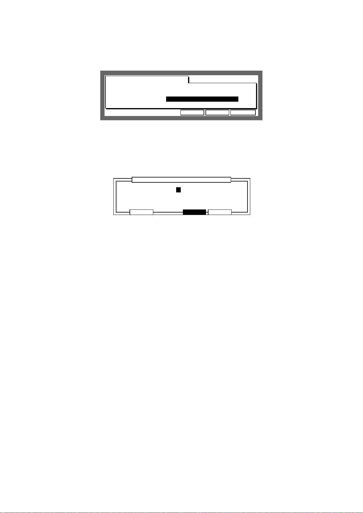
Chapter 5: Song Mode
Select the next sequence (assigned to Step 2), with the DATA wheel.
Song:01-Song01 Now:003.01.00
.......................................................
TEMPO:MAS
™:120.0
LOOP:OFF
Step Sequence Reps
.....................................................................
1 01-Sequence01 1
2 02-Sequence02 1
(end of song)(end of song)
................
................
................
INSERTCONVRT DELETE
In the same way as above, assign sequences and increase the number of steps.
Renaming a Song
To open the Song window, select the Song: field and press OPEN WINDOW.
......................................................................................................
Song name:Song01
.................................................................................................
Default name :songDefault name :song
........................
.........................................................................................................
SONG
CLOSE COPYDELETE
............................
• Song name:
Changes the name of the song.
Tap a drum pad or rotate the DATA wheel to display the name window.
Press ENTER after you have entered the name.
Note: If you do not press the ENTER key and move the
Default Name:
other pages with the CURSOR DOWN key, the entered name will be ignored and
the name will not change.
• Default name:
This sets the name that will automatically be used when data is entered into a new song
(titled “Unused”). Enter the name in the same way as for the Song name.
field or
Page 79
Page 91

Selecting a Song
Chapter 5: Song Mode
Song:01-Song01
.......................................................
TEMPO:MAS
™:120.0
LOOP:OFF
Step Sequence Reps
.....................................................................
1 01-Sequence01 1
2 02-Sequence02 1
................
................
Now:003.01.00
................
INSERTCONVRT DELETE
Move the cursor to the Song: field and select a song by rotating the DATA wheel. The song
number and song name will appear. If there is no data in the song, (Unused) will appear.
Deleting a Song
From the song screen, select the Song: field and press OPEN WINDOW.
To open the Delete Song window, press DELETE [F2].
....................................................................................
Song:01-Song01
Pressing DO IT willPressing DO IT will
erase this song!!erase this song!!
........................
........................................................................................
The currently selected song is erased when DO IT [F5] is pressed and the song name will
change to (Unused).
Delete SongDelete Song
CANCEL DO ITALL SG
...........................
If you press ALL SG [F3] the following warning will appear and all the songs will be erased if you
press DO IT [F5].
....................................................................................
........................
........................................................................................
Delete ALL SongDelete ALL Song
Pressing DO IT will erasePressing DO IT will erase
ALL songs!!ALL songs!!
CANCEL DO IT
...........................
Page 80
Page 92

Chapter 5: Song Mode
Copying a Song
From the song screen, select the Song: field and press the OPEN WINDOW key.
To open the Copy Song window, press COPY[F5].
....................................................................................
Song:01-Song01
Song:02-(Unused)
........................
........................................................................................
Copy SongCopy Song
Copy
CANCEL DO IT
...........................
Select the song that you want to copy (top level) with the DATA wheel.
Select the copy destination (bottom level) by pressing the CURSOR DOWN key and select the
song that you want to copy the data to with the DATA wheel.
To copy the song data, press DO IT [F5].
CAUTION: If there is data in the song you have selected as the destination, the data will
be erased if you press F5. Be careful when you are copying to a song with a
name other than “Unused.”
Page 81
Page 93
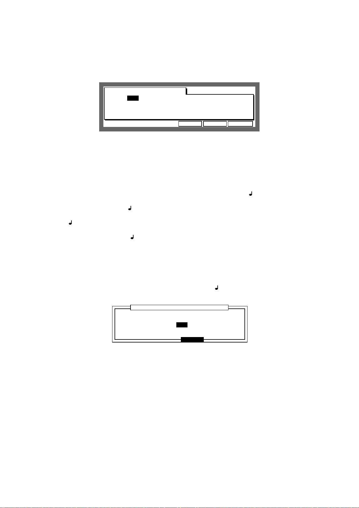
Chapter 5: Song Mode
Setting the Tempo
This sets the tempo of the song.
Song:01-Song01 Now:001.01.00
.......................................................
TEMPO:MAS
™:120.0
LOOP:OFF
TEMPO:
•
This sets the sequence to either be played in the tempo it was recorded in or the Master
tempo.
Move the cursor to the TEMPO: field and set the tempo source by rotating the DATA
wheel.
SEQ The song will be played at the tempo specified in the sequence. In this
case it is not necessary to change the tempo in the : field.
MAS All the sequences in the song will be played at the Master tempo specified
in the : field.
Step Sequence Reps
.....................................................................
1 01-Sequence01 1
2 02-Sequence02 1
................
................
................
INSERTCONVRT DELETE
• :
Set the tempo of the song, if MAS is selected in the TEMPO: field.
Move the cursor to the : field and set the tempo by rotating the DATA wheel.
Enter 4 digits if you are using the numeric pad to enter. For example, to set the value to
120.5, enter “1205” and press ENTER. To set the value to 88.5, enter “885” and press
ENTER.
When SEQ is selected in the TEMPO: field, you can not change the tempo. The current
tempo of the sequence is displayed in this field.
To open the Tempo Change window, select the TEMPO: or : field and press the OPEN WINDOW key.
......................................................................................................
Ignore tempo change eventsIgnore tempo change events
in sequence: ON
........................
.........................................................................................................
Tempo changeTempo change
CLOSE
............................
Specify whether the tempo change recorded within the sequence should be ignored.
If ON is selected, the tempo change in the sequence will be ignored. If OFF is selected, the
tempo change in the sequence becomes valid and the tempo of the song will change according to
the data.
Page 82
Page 94

Chapter 5: Song Mode
Setting the Loop
This allows you to repeatedly play a loop of a specified number of steps of the song until STOP is
pressed.
Song:01-Song01 Now:001.01.00
.......................................................
TEMPO:MAS
™:120.0
LOOP:OFF
Select the LOOP: field with the CURSOR keys and rotate the DATA wheel to select ON (set to
OFF to cancel the loop mode).
To set the range of the loop, press OPEN WINDOW.
Step Sequence Reps
.....................................................................
1 01-Sequence01 1
2 02-Sequence02 1
................
................
................
INSERTCONVRT DELETE
First step:
•
......................................................................................................
First step: First step: 1
Last step: 1Last step: 1
Number of steps: 2Number of steps: 2
........................
........................................................................................................
Loop
CLOSE
............................
Specifies the first step of the loop.
Last step:
•
Specifies the last step of the loop.
Number of steps:
•
This sets the range of the loop by the number of steps. The song will loop from First
step: for the number of bars set here.
CAUTION: The
First step:
step:
and the
Number of steps:
First step:
and the
or
Last step:
Number of steps:
affect each other. If you change the
, the value of
Number of steps:
as well as the
will change accordingly.
Last
Page 83
Page 95

Chapter 5: Song Mode
Selecting a Step and Changing the Sequence
Select the step number in the Step field with the CURSOR keys. If there are a lot of steps, press
the CURSOR UP or DOWN key to scroll up and down the screen.
You can also use the DATA wheel to select the step.
Song:01-Song01 Now:003.01.00
.......................................................
TEMPO:MAS
™:120.0
LOOP:OFF
To change the sequence assigned to that step, move the cursor to the Sequence section with
the CURSOR RIGHT key.
Song:01-Song01 Now:003.01.00
.......................................................
TEMPO:MAS
™:120.0
LOOP:OFF
Step Sequence Reps
.....................................................................
1 01-Sequence01 1
2 02-Sequence02 1
(end of song)(end of song)
................
................
Step Sequence Reps
.....................................................................
1 01-Sequence01 1
2 03-Sequence03 1
(end of song)(end of song)
................
................
................
INSERTCONVRT DELETE
................
INSERTCONVRT DELETE
Change the sequence with the DATA wheel.
Repeating a Sequence
The sequence assigned to the step can be repeated a number of times.
Select the Reps field of the sequence you want to repeat with the CURSOR keys.
Song:01-Song01
.......................................................
TEMPO:MAS
™:120.0
LOOP:OFF
Step Sequence Reps
.....................................................................
1 01-Sequence01 3
2 02-Sequence02 1
................
................
Set the number of times the sequence is to be repeated with the DATA wheel.
CAUTION: If this is set to 0, the sequences after that step will not be played.
Now:003.01.00
................
INSERTCONVRT DELETE
Page 84
Page 96

Chapter 5: Song Mode
Deleting a Step
Select the step number or sequence that you want to delete with the CURSOR keys and press
DELETE[F5].
When the step is deleted, the following steps will all be moved up.
Song:01-Song01 Now:007.01.00
.......................................................
TEMPO:SEQ
™:120.0
LOOP:OFF
Song:01-Song01 Now:007.01.00
.......................................................
TEMPO:MAS
™:120.0
LOOP:OFF
Step Sequence Reps
.....................................................................
1 01-Sequence01 3
2 03-Sequence03 1
(end of song)(end of song)
................
................
Step Sequence Reps
.....................................................................
1 01-Sequence01 3
2 03-Sequence03 1
(end of song)(end of song)
................
................
................
INSERTCONVRT DELETE
................
INSERTCONVRT DELETE
Inserting a Step
Select the step number or sequence where you want to insert the new step with the CURSOR
keys and press INSERT[F6]. The new step is inserted after the selected step.
The steps after the selected one will move one step back and sequence 01 will be inserted.
Move the cursor to the Sequence field of the new step and select a new sequence by rotating
the DATA wheel.
Page 85
Page 97

Chapter 5: Song Mode
Moving to a Specific Point in the Song
Select the Now: field with the CURSOR keys and set the point in the song that you want to go to
with the CURSOR keys and DATA wheel.
Song:01-Song01 Now:001.01.00
.......................................................
TEMPO:MAS
™:120.0
LOOP:OFF
You can set the Now: field to display either bar/beat/clock or hours/minutes/seconds.
While still on the Now: field, press OPEN WINDOW.
Step Sequence Reps
.....................................................................
1 01-Sequence01 1
2 01-Sequence01 1
................
................
................
INSERTCONVRT DELETE
Display style:
•
......................................................................................................
Display style:BAR,BEAT,CLOCK
Start time:00h00m00s00f00
Frame rate:25
........................
.........................................................................................................
Time DisplayTime Display
CLOSE
............................
Select either BAR,BEAT,CLOCK or HOUR,MINUTE,SEC.
Start time:
•
Select HOUR,MINUTE,SEC in Display style: to start the time display on the
main screen from the time set in this field. This is also the start time when synchronizing to
MTC or SMPTE time code.
Frame rate:
•
This sets the frame rate of the time code used when synchronizing to MTC or SMPTE time
code. Synchronization is described in the “MIDI/SYNC Mode” section.
Page 86
Page 98

Chapter 5: Song Mode
Converting a Song to a Sequence
The song mode function is convenient when assembling a song. When editing detailed data within
a song that has a complicated structure, it’s easier to assemble the song as 1 sequence and then
edit that sequence. In this type of case, it is a good idea to create the basic structure of the song
using the song mode and then convert that to one sequence. By doing that you can then use the
sequence’s edit function to further edit the song. When converted, the songs complete sequence
will be converted to a newly created sequence.
Note: Sequence settings set in step1 of the song will be applied as the settings of the new
sequence such as track name, track type (Drum or MIDI), MIDI OUT channel assign, MIDI
Program Change Assign, mixer, tuning, tempo etc.. Also, song loop settings will be made
effective by the converted sequence.
To convert the song, press CONVRT [F4].
......................................................................................................
From song:01-Song01
To sequence:03-(Unused)
....................................................................................................
Track status:REFERENCED TO 1ST SQTrack status:REFERENCED TO 1ST SQ
........................
.........................................................................................................
Convert Song to SeqConvert Song to Seq
CLOSE DO IT
............................
• From song:
This selects the song that you want to convert.
• To sequence:
This selects the sequence where the song will be converted to.
• Track status:
Here you can select what the track status will be after conversion to a sequence.
REFERENCED TO 1ST SQ
The settings (MIDI output, stereo mixer settings, tempo settings, etc.) in each track of
the first sequence will be assigned to all of the following sequences.
OFF TRACKS IGNORED
Tracks that have been turned off (track “ON:” is set to “NO” on the Main Screen) will
not be converted. All tracks will be turned on after conversion, but the data in tracks
that have been turned off will be blank.
All the parameter settings of the first sequence will be used for the new sequence.
MERGED ON MIDI CH
Each sequence will be merged according to their MIDI output channels to the corresponding tracks.
For example:
All track data of MIDI channels 1A-16A will be merged to tracks 1-16
All track data of MIDI channels 1B-16B will be merged to track 17-32
Drum tracks 1 - 4 will be merged to tracks 33 - 36 consecutively.
The Exclusive data will be merged to tracks 1-32 according to the MIDI channel
assigned on each track.
To convert, press DO IT [F5].
CAUTION: If there is data in the sequence you have selected as the destination, the data will
be erased. Be careful when you are converting to a sequence with a name other
than “Unused” .
If the size of the sequence will exceed 50,000 notes after conversion, it will not be
converted.
Page 87
Page 99

Chapter 6
Creating and Editing
Sounds
Page 100

Chapter 6: Creating and Editing Sounds
Sampling a New Sound
Sampling is done in 16-bit linear format with the same 44.1kHz sampling rate as used with compact discs.
CAUTION: All sounds are lost when the power is turned off. This means that you must
load in sounds from a disk every time the MPC2000XL is turned on, and you
must save any edited or newly sampled sounds to disk, or the changes will be
lost!
To sample a sound, hold down SHIFT and press SAMPLE (or 4 on the numeric pad) to display the
sampling screen.
Input:ANALOG Mode:STEREO Monitor:L/R
Threshold:-20 Time: 10.0sTime: 10.0s Pre-rec:100ms
LEVEL METERLEVEL METER
LEFT :LEFT :
RIGHT:
RECORDRESET PEAKRESET PEAK
Input:
•
You can choose from the following two sound sources.
ANALOG The recording source is connected to the rear panel analog RECORD IN
jacks.
DIGITAL The recording source is connected to the DIGITAL input on the rear
panel. This input can be connected to any 44.1kHz digital SP/DIF source
such as a CD or DAT tape recorded at 44.1kHz, but 48 kHz sources are
not supported.
CAUTION: You can only choose
DIGITAL
when the optional IB-M208P board is
installed.
Mode:
•
Set the mode to STEREO or MONO input.
MONO L Sampling is done in mono, using only the left RECORD IN (or the LEFT
signal of DIGITAL IN). The mono signal is monitored at both the left and
right sides of the stereo outputs, but the level meter will only show LEFT.
MONO R Sampling is done in mono, using only the right RECORD IN (or the
RIGHT signal of DIGITAL IN). The mono signal is monitored at both the
left and right sides of the stereo outputs, but the level meter will only show
RIGHT.
STEREO Sampling is done in stereo, using both the LEFT and RIGHT RECORD IN
(or the LEFT and RIGHT si1gnals of DIGITAL IN).
Page 89
 Loading...