


 Loading...
SELPHY DS700
SERVICE
MANUAL
Canon
Copyright 2004, Canon U.S.A. This technical publication is the proprietary and confidential information of Canon U.S.A. which shall be retained for reference purposes by Authorized Service Facilities of Canon U.S.A. Its unauthorized use is prohibited.
Download Service Manual And Resetter Printer at http://printer1.blogspot.com

Scope
This manual has been issued by Canon Inc., to provide the service technicians of this product with the information necessary for qualified persons to learn technical theory, installation, maintenance, and repair of products. The manual covers information applicable in all regions where the product is sold. For this reason, it may contain information that is not applicable to your region.
Revision
This manual could include technical inaccuracies or typographical errors due to improvements or changes made to the product. When changes are made to the contents of the manual, Canon will release technical information when necessary. When substantial changes are made to the contents of the manual, Canon will issue a revised edition.
The following do not apply if they do not conform to the laws and regulations of the region where the manual or product is used:
Trademarks
Product and brand names appearing in this manual are registered trademarks or trademarks of the respective holders.
Copyright
All rights reserved. No parts of this manual may be reproduced in any form or by any means or translated into another language without the written permission of Canon Inc., except in the case of internal business use.
Copyright © 2004 by Canon Inc. CANON INC.
Inkjet SFP Quality Assurance Div.
16-1, Shimonoge 3-chome, Takatsu-ku, Kawasaki, Kanagawa 213-8512, Japan
Download Service Manual And Resetter Printer at http://printer1.blogspot.com

I. MANUAL OUTLINE
This manual consists of the following three parts to provide information necessary to service the SELPHY DS700:
Part 1: Maintenance
Information on maintenance and troubleshooting of the SELPHY DS700
Part 2: Technical Reference
New technology and technical information such as FAQ's (Frequently Asked Questions) of the SELPHY DS700
Part 3: Appendix
Block diagrams and pin layouts of the SELPHY DS700
Reference:
This manual does not provide sufficient information for disassembly and reassembly procedures. Refer to the graphics in the separate Parts Catalog.
Download Service Manual And Resetter Printer at http://printer1.blogspot.com
II. TABLE OF CONTENTS
Part 1: MAINTENANCE
1. MAINTENANCE
1-1. Adjustment, Periodic Maintenance, Periodic Replacement Parts, and Replacement Consumables by Service Engineer
(1)Adjustment
(2)Periodic maintenance
(3)Periodic replacement parts
(4)Replacement consumables
(5)Replacement of the print head
1-2. Customer Maintenance
1-3. Product Life
(1)Printer
(2)Print head
(3)Ink tank
1-4. Special Tools
1-5. Serial Number Location
2. LIST OF ERROR DISPLAY / INDICATIONS
2-1. Operator Call Errors
2-2. Service Call Errors
2-3. Warnings
2-4. Troubleshooting by Symptom
3. REPAIR
3-1. Notes on Service Part Replacement
3-2. Special Notes on Repair Servicing
(1)Flexible cable and harness wiring, connection
(2)Notes on disassembly and re-assembly
3-3. Adjustment / Settings
(1)Paper feed motor adjustment
(2)Access cover gear phase adjustment
(3)Pump unit adjustment
(4)Grease application
(5)Waste ink counter setting
(6)User mode
(7)Service mode
3-4. Verification Items
(1)Service test print
(2)EEPROM information print
4. PRINTER TRANSPORTATION
Part 2: TECHNICAL REFERENCE
1. NEW TECHNOLOGIES
(1)Robust direct printing
(2)Card direct printing
(3)PictBridge / Canon Bubble Jet Direct supporting
(4)Infrared printing
(5)New design
(6)New print head and ink tank
(7)Memory card access functionality
2. CLEANING MODE AND AMOUNT OF INK PURGED
3. PRINT MODE
3-1. Resolution during Printing via Computer
3-2. Resolution in Card Direct / Camera Direct / Infrared Printing 4. PHOTO DIRECT PRINT FUNCTION
4-1. Host PC Memory Card Access Function
(1)Supported memory cards
(2)Mounting the drive
(3)Arrangement of image files
(4)Data access
(5)Card slot attribute
4-2. Memory Card Direct Printing Function
(1) Slide show
Download Service Manual And Resetter Printer at http://printer1.blogspot.com
(2)Print mode
(3)Print quality
(4)Supported image formats
(5)Supported file names
4-3. File Search
4-4. File Sort
4-5. Date Print
4-6. Canon Bubble Jet Direct Function
(1)Print mode
(2)Media type
(3)Print layout
(4)Print quality
(5)Image correction function
(6)Maintenance
(7)Print date
(8)Copies
4-7. PictBridge Function
(1)Print mode
(2)Media type
(3)Print layout
(4)Print quality
(5)Image correction function
(6)Image adjustment
(7)Image processing
(8)Maintenance
(9)Print date
(10)Copies
(11)Digital camera's standard setting
4-8. Exclusive Processes
(1)Exclusive processes in Memory Card Direct Printing and Digital Camera Direct Printing
(2)Exclusive process control between Direct Printing and printing from the host computer
(3)Exclusive processes in host computer memory card access and Memory Card Direct Printing
(4)Exclusive processes between the memory card and memory card
4-9. Display
4-10. Card Slot-related Operations and Display
(1)Timing and precautions when removing the memory card
(2)Power supply/cut to the memory card
(3)Memory card removal command from the host computer
4-11. DPOF Settings in the Memory Card Direct Printing Function
(1)Supported DPOF functions
(2)Print specifications in DPOF print mode
4-12. Print Layout (Details)
(1)Selectable layout in Memory Card Direct Printing
(2)Selectable layout in Digital Camera Direct Printing
(3)Selectable layout in Infrared Printing (Direct Printing from a Mobile Phone via Infrared Communication)
(4)Layout in Memory Card Direct Printing
(5)Layout and image size
4-13. Date Print Specifications
(1)Date print in Memory Card Direct Printing
(2)Date print in Digital Camera Direct Printing
(3)Date print in Infrared Printing
4-14. Photo Number Printing Specifications
(1)Photo number printing in Memory Card Direct Printing
(2)Photo number printing in Digital Camera Direct Printing
(3)Photo number printing in Infrared Printing
5. FAQ (Problems Specific to the SELPHY DS700 and Corrective Actions)
Part 3: APPENDIX
1. BLOCK DIAGRAM
2. CONNECTOR LOCATION AND PIN LAYOUT
2-1. Main Board
2-2. Panel Board
2-3. Front I/F Board
2-4. Rear I/F Board
3. SPECIFICATIONS
Download Service Manual And Resetter Printer at http://printer1.blogspot.com

Part 1
MAINTENANCE
Download Service Manual And Resetter Printer at http://printer1.blogspot.com

1. MAINTENANCE
1-1. Adjustment, Periodic Maintenance, Periodic Replacement Parts, and Replacement Consumables by Service Engineer
(1) Adjustment |
|
|
|
|
|
Adjustment |
Timing |
Purpose |
|
Tool |
Approx. |
|
time |
||||
|
|
|
|
|
|
Destination |
At logic board ass'y replacement |
To set the destination. |
None. |
|
1 min. |
settings |
|
|
|
|
|
(EEPROM |
|
|
|
|
|
settings) |
|
|
|
|
|
Language settings |
At logic board ass'y replacement |
To set the language to be displayed on |
|
|
the TV. |
Waste ink counter |
- At logic board ass'y replacement |
To reset the waste ink counter. |
resetting |
- At waste ink absorber |
|
(EEPROM |
replacement |
|
settings) |
|
|
Paper feed motor |
- At paper feed motor ass'y |
To adjust the belt tension. (Position the |
ass'y position |
replacement |
paper feed motor so that the belt is |
adjustment |
|
stretched tight.) |
Access cover gear |
- At access cover unit |
To adjust the access cover damper. |
phase adjustment |
replacement |
|
|
- At main cover unit replacement |
|
TV (in the user |
1 min. |
mode) |
|
None. |
1 min. |
None. |
2 min. |
None. |
1 min. |
Pump unit adjustment
Grease application
-At pump unit replacement
-At purge tube replacement
-At pump drive gear replacement
-At carriage unit / carriage shaft replacement
-At access cover unit replacement
-At feed roller ass'y replacement
To set an accurate ink absorption function.
To maintain sliding properties of the:
-carriage oil pad / carriage shaft, carriage rail.
-access cover, and
-feed roller ass'y.
None. |
2 min. |
- GREASE EU-1 |
1 min. |
-MOLYKOTE PG641
-FLOIL KG-107A
Note: DO NOT loosen the 2 red screws on both front sides of the main chassis, adjusting the head-to-paper distance.
The red screws securing the paper feed motor ass'y may be loosened only at replacement of the paper feed motor ass'y.
(2) Periodic maintenance
No periodic maintenance is necessary.
(3) Periodic replacement parts
There are no parts in this printer that require periodic replacement by a service engineer.
(4) Replacement consumables
There are no consumables that require replacement by a service engineer.
(5) Replacement of the print head
Procedures:
1)Press the Power button to turn on the printer.
2)Open the access cover.
=> The print head holder will move to the ink tank replacement position (to the left), and the LED blinks in green. 3) Press and hold the Resume/Cancel button for 2 seconds or longer.
=> The print head holder will move to the print head replacement position (to the right), and the LED blinks in green. 4) Raise the print head lock lever.
=> The print head can be removed from the holder.
5) Replace the print head, following the instructions in the user's guide.
1 - 1
Download Service Manual And Resetter Printer at http://printer1.blogspot.com

1-2. Customer Maintenance
Adjustment |
Timing |
Purpose |
Tool |
Approx. time |
Print head cleaning |
When print quality |
To improve nozzle |
- Remote control and connection to a |
42 sec. |
|
is not satisfying. |
conditions. |
TV |
|
|
|
|
- Printer button |
|
|
|
|
- Computer (settings via the printer |
|
|
|
|
driver) |
|
Print head deep cleaning |
When print quality |
To improve nozzle |
- Remote control and connection to a |
82 sec. |
|
is not satisfying, |
conditions. |
TV |
|
|
and not improved |
|
- Computer (settings via the printer |
|
|
by print head |
|
driver) |
|
|
cleaning. |
|
|
|
Ink tank replacement |
When the ink tank |
|
|
2 min. |
|
becomes empty. |
--- |
--- |
|
|
(No ink error) |
|
|
|
Print head alignment |
When print quality |
To ensure accurate dot |
- Remote control and connection to a |
1 min. |
|
is not satisfying. |
placement. |
TV |
|
|
|
|
- Computer (settings via the printer |
|
|
|
|
driver) |
|
Print head alignment value |
When confirming |
To confirm the current |
- Remote control and connection to a |
25 sec. |
printing |
the print head |
print head alignment |
TV |
|
|
alignment values set |
values. |
|
|
|
in the printer. |
|
|
|
Language selection |
When necessary. |
To select the TV display |
- Remote control and connection to a |
10 sec. |
|
|
language. |
TV |
|
Paper feed roller cleaning |
When paper does |
To clean the paper feed |
- Printer button |
2 min. |
|
not feed properly, |
roller. |
|
|
|
or the paper feed |
|
|
|
|
roller is soiled. |
|
|
|
Bottom plate cleaning |
After printing is |
To cleaning the bottom |
- Printer button |
40 sec. |
|
performed on the |
plate and platen ribs. |
|
|
|
wrong side of |
|
|
|
|
paper, or rollers |
|
|
|
|
inside the printer |
|
|
|
|
are extremely |
|
|
|
|
soiled. |
|
|
|
1-3. Product Life
(1) Printer
Specified print volume (I) or the years of use (II), whichever comes first.
(I) Print volume: 2,000 pages (4" x 6", borderless printing, standard photo) (II) Years of use: 5 years
(2) Print head
Print volume: 2,000 pages (4" x 6", borderless printing, standard photo)
(3) Ink tank
BCI-16 Color: Approx. 75 pages (4" x 6", borderless printing, PP-101, standard mode printing from a computer)
1 - 2
Download Service Manual And Resetter Printer at http://printer1.blogspot.com
1-4. Special Tools
Name |
Tool no. |
Application |
Remarks |
MOLYKOTE |
CK-0562-000 |
To be applied to the sliding portion of the |
In common with |
PG641 |
|
access cover arm, and feed roller ass'y. |
other models. |
FLOIL KG- |
QY9-0057-000 |
To be applied to the sliding portion of the |
In common with |
107A |
|
carriage guide rail. |
other models. |
EU-1 |
QY9-0037-000 |
To be applied to the carriage oil pad, and the |
In common with |
|
|
sliding portion of the carriage shaft. |
other models. |
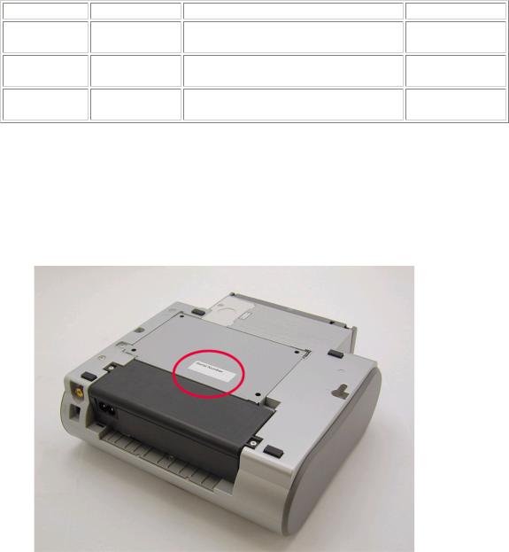
1-5. Serial Number Location
On the bottom shield plate.
To the top
 <Part 1: MAINTENANCE>
1 - 3
Download Service Manual And Resetter Printer at http://printer1.blogspot.com

2. LIST OF ERROR DISPLAY / INDICATIONS
Errors and warnings are displayed by the following ways:
1)Errors are indicated by the number of times the LED blinks.
2)Errors and warnings are displayed on the TV.
3)Errors and warnings are displayed on the printer driver's Status Monitor.
2-1. Operator Call Errors
(by LED Blinking in Orange) |
|
|
|
LED |
|
|
|
blinking |
Error [Error code] |
Solution |
Remarks |
in orange |
|
|
|
2 times |
No paper. (ASF) [1000] |
Set the paper in the ASF, and press the |
|
|
|
Resume/Cancel button. |
|
3 times |
Paper jam. [1300] |
Remove the jammed paper, and press the |
|
|
|
Resume/Cancel button. |
|
4 times |
No ink tank. [1662] |
5 times |
- The print head is not |
|
installed, or it is not |
|
properly installed. [1401] |
|
- EEPROM data of the print |
|
head is faulty. [1403 / |
|
1405]. |
8 times |
Warning: The waste ink |
|
absorber is almost full |
|
(approx. 95% of the |
|
maximum capacity). [1700] |
9 times |
The connected digital camera |
|
or digital video camera does |
|
not support Camera Direct |
|
Printing. [2001] |
|
Access cover open. [1200] |
Install an ink tank, and press the Resume/Cancel button.
-Install the print head properly, and close the access cover, or, with the print head installed, turn the printer off and on.
-If the error is still not resolved, the print head may be defective. Replace the print head.
Pressing the Resume/Cancel button will exit the error, and enable printing.
In repair servicing, replace the ink absorbers.
After removing the cable between the camera and the printer, press the Resume/Cancel button, and re-connect the cable. If the error is still not resolved, a non-supported camera may be connected. Connect a supported camera.
Close the access cover.
The service call error, indicating the waste ink absorber is full, is likely to occur soon.
2-2. Service Call Errors
(by LED Blinking in Orange and Green Alternately, or Lit in Orange)
LED alternate |
|
blinking in orange |
Error [Error code] |
and green |
|
2 times |
Carriage error [5100] |
Solution
(Replacement of listed parts, which are likely to be faulty)
-Carriage unit (QM2-1974)
-Timing slit strip film (QC1-5153)
-Logic board ass'y (QM2-1961)*1
-Carriage motor ass'y (QM2-1744)
1 - 4
Download Service Manual And Resetter Printer at http://printer1.blogspot.com
3 times |
Paper feed error [6000] |
- Timing sensor unit (QM2-1759) |
|
|
- Timing slit disk ass'y (QL2-0843) |
|
|
- Paper feed motor ass'y (QM2-1746) |
|
|
- Feed roller ass'y (QM2-1970) |
|
|
- Platen (QC1-5176/5177) |
|
|
- Logic board ass'y (QM2-1961)*1 |
4 times |
Purge unit error [5C00] |
- Purge unit (QM2-1975) |
|
|
- Logic board ass'y (QM2-1961)*1 |
5 times |
ASF cam sensor error [5700] |
- Sheet feed unit (QM2-1964) |
6 times |
Internal temperature error [5400] |
- Logic board ass'y (QM2-1961)*1 |
7 times |
Waste ink absorber full [5B00] |
- Ink absorber (QC1-5195 / 5196 / 5566 / 5567 / 5568) |
|
|
- After replacement of the ink absorber, reset the EEPROM |
|
|
(waste ink amount value) on the logic board ass'y. |
8 times |
Print head temperature rise error |
- Print head (QY6-0056) |
|
[5200] |
- Logic board ass'y (QM2-1961)*1 |
9 times |
EEPROM error [6800] |
- Logic board ass'y (QM2-1961)*1 |
Continuous |
ROM error |
- Logic board ass'y (QM2-1961)*1 |
alternate blinking |
|
|
Lights in orange |
RAM error |
- Logic board ass'y (QM2-1961)*1 |
*1: Before replacement of the logic board ass'y, check the waste ink amount (by service test print or EEPROM information print). If the waste ink amount is 7% or more, also replace the ink absorbers (QC1-5195 / 5196 / 5566 / 5567 / 5568 ) when replacing the logic board ass'y.
[See Section 3-3. Adjustment / Settings, (7) Service mode, for details.]
2-3. Warnings
Printer (displayed via the Status Monitor or on the TV, no LED indication): |
|
Displayed warning |
Remarks |
Ink low warning 1 (approx. half level)
The warning is displayed only when printer driver's Low Ink Warning Setting is enabled.
Ink low warning 2 (low remaining ink, display of "!" in the warning)
Ink low warning 3 (ink level unknown, display of "?" in the warning)
Print head temperature rise
The warning is displayed only when printer driver's Low Ink Warning Setting is enabled.
The warning is displayed only when printer driver's Low Ink Warning Setting is enabled.
If the print head temperature is high when the access cover is opened, the warning is displayed.*1
|
When the print head temperature falls below the specified |
|
temperature, the warning is released. |
Protection against excess rise of the print head temperature |
If the print head temperature exceeds the specified limit, a |
|
Wait is inserted during printing, |
|
When the print head temperature falls below the specified |
|
temperature, the warning is released. |
*1: If the warning is displayed, the carriage does not move to the ink tank replacement position when the access cover is opened.
1 - 5
Download Service Manual And Resetter Printer at http://printer1.blogspot.com

2-4. Troubleshooting by Symptom
Faulty operation
Paper feed problems
Unsatisfactory print quality
Symptom
The power does not turn on.
The power turns off immediately after power-on.
The print head is not recognized.
The print head does not return to the home position.
Strange noise.
Printing stops mid-way.
Multiple sheets feed.
Paper does not feed.
Paper feeds at an angle.
No printing, or no color ejected.
Printing is faint, or white lines appear on printouts even after print head cleaning.
Line(s) not included in the print data appears on printouts.
Paper gets smeared.
A part of a line is missing on printouts.
Color hue is incorrect.
Printing is incorrect.
Non-ejection of ink.
1 - 6
Solution
Replace the
-AC adapter, or
-logic board ass'y*1.
Remove and re-install the print head, or replace the
-print head, or
-logic board ass'y*1.
Remove foreign material, or attach a removed part if any.
Replace the logic board ass'y*1. Replace the
-sheet feed unit, or
-output tray unit.
Remove foreign material, or replace the
-sheet feed unit, or
-output tray unit.
Remove foreign material, or adjust the paper guide, or replace the
-sheet feed unit, or
-output tray unit.
Replace the
-ink tank,
-print head*2,
-logic board ass'y*1, or
-purge unit.
Remove and re-install the print head, or replace the
-ink tank,
-print head*2,
-purge unit, or
-logic board ass'y*1.
Feed several sheets of paper,
perform bottom plate cleaning*3, or
clean the paper path with cotton swab or cloth.
Replace the
-ink tank, or
-print head*2.
Replace the
-ink tank, or
-print head*2, or
perform print head alignment. Replace the logic board ass'y*1.  Replace the
Download Service Manual And Resetter Printer at http://printer1.blogspot.com

Graphic or text is enlarged on printouts.
-ink tank, or
-print head*2.
When enlarged in the carriage movement direction, clean grease or oil off the timing slit strip film, or replace the
-timing slit strip film,
-carriage unit, or
-logic board ass'y*1.
When enlarged in the paper feed direction, clean grease or oil off the timing slit disk ass'y, or replace the
- timing slit disk ass'y, - timing sensor unit, or - logic board ass'y*1.
*1: Before replacement of the logic board ass'y, check the waste ink amount (by service test print or EEPROM information print). If the waste ink amount is 7% or more, also replace the ink absorbers (QC1-5195 / 5196 / 5566 / 5567 / 5568 ) when replacing the logic board ass'y.
[See Section 3-3. Adjustment / Settings, (7) Service mode, for details.]
*2: Replace the print head only after the print head deep cleaning is performed 2 times, and when the problem persists.
*3: To perform bottom plate cleaning, with the printer power turned on, press and hold the Resume/Cancel button until the Power lamp blinks 5 times, then release the button. For details, see Section 3-3. Adjustment / Settings, (6) User mode.
To the top
 <Part 1: 2. LIST OF ERROR DISPLAY / INDICATION>
1 - 7
Download Service Manual And Resetter Printer at http://printer1.blogspot.com

3. REPAIR
3-1. Notes on Service Part Replacement
Service part
Logic board ass'y (QM2-1961)
Notes on replacement*1
-Before removal of the logic board ass'y, remove the power cord, and allow for to sit approx. 1 minute (for discharge of capacitor's accumulated charges), to prevent damage to the logic board ass'y.
-Before replacement, check the waste ink amount (by service test print or EEPROM information print). If the waste ink amount is 7% or more, also replace the ink absorbers when replacing the logic board ass'y.
[See 3-3. Adjustment / Settings, (7) Service mode, for details.]
Ink absorber
(QC1-5195 / 5196 / 5566 / 5567 / 5568)
Carriage unit (QM2-1974)
Paper feed motor ass'y (QM2-1746)
Access cover unit (QM2-1982) Main cover unit (QM2-1955)
Pump unit (QM2-1979), Purge Tube (QC1-5555), Pump Drive Gear (QC1-5253)
Carriage shaft (QC1-5150)
-The red screws securing the paper feed motor are allowed to be loosened. (For any purposes other than paper feed motor replacement, DO NOT loosen them.)
1 - 8
|
Adjustment / settings |
Operation check |
After replacement: |
- Service test print |
|
1. |
Initialize the EEPROM. |
- EEPROM |
2. |
Reset the waste ink counter. |
information print |
3. |
Set the destination in the |
- Printing via USB |
|
EEPROM. |
connection |
[See 3-3. Adjustment / Settings, |
- Digital Camera |
|
(7) Service mode, for details of 1 |
Direct Printing |
|
to 3] |
- Memory Card |
|
4. |
Set the TV display language in |
Direct Printing |
|
the user mode. |
- Infrared Printing |
5. |
Perform the print head |
- Connection to the |
|
alignment in the user mode. |
TV |
After replacement: |
- Service test print |
|
1. |
Reset the waste ink counter. |
- EEPROM |
[See 3-3. Adjustment / Settings, |
information print |
|
(7) Service mode.] |
|
|
At replacement: |
- Service test print |
|
1.Apply grease to the entire surface of the carriage oil pads (2 pcs.).
2.Apply grease to the sliding portions.
[See 3-3. Adjustment / Settings,
(4) Grease application.]
After replacement:
1.Perform the print head alignment in the user mode.
After replacement:
1. Adjust the paper feed motor.
[See 3-3. Adjustment / Settings,
(1) Paper feed motor adjustment.]
After replacement:
Adjust the phase of the access cover arm and access cover gear. [See 3-3. Adjustment / Settings,
(2) Access cover gear phase adjustment.]
-Service test print
-Opening and closing of the
access cover
After replacement: |
- Service test print |
Perform the pump unit |
|
adjustment. |
|
[See 3-3. Adjustment / Settings, |
|
(3) Pump unit adjustment.] |
|
At replacement: |
- Service test print |
1. Apply grease to the sliding |
|
portions. |
|
[See 3-3. Adjustment / Settings, |
|
(4) Grease application.] |
|
Download Service Manual And Resetter Printer at http://printer1.blogspot.com

Timing slit strip film (QC1-5153)
Timing slit disk ass'y (QL2-0843)
Print head (QY6-0056)
*1: General notes:
- Upon contact with the film, wipe the After replacement: |
- Service test print |
||
film with ethanol. |
1. |
Perform the print head |
|
- Confirm no grease is on the film. |
|
alignment in the user mode. |
|
(Wipe off any grease thoroughly |
|
|
|
with ethanol.) |
|
|
|
- Do not bend the film. |
|
|
|
|
After replacement: |
- Service test print |
|
|
1. |
Perform the print head |
|
|
|
alignment in the user mode. |
|
-Make sure that the flexible cables and wires in the harness are in the proper position and connected correctly. [See 3-2. Special Notes on Repair Servicing, (1) Flexible cable and harness wiring, connection, for details.]
-Do not drop the ferrite core, as it may damage the core.
-Protect electrical parts from damage due to static electricity.
-Before removing a unit, after removing the power cord, allow the printer to sit for approx. 1 minute (for capacitor discharging to protect the logic board ass'y from damages).
-Do not touch the timing slit strip film and timing slit disk ass'y. No grease or abrasion is allowed.
-Protect the units from becoming soiled with ink.
-Protect the housing from scratches.
-Exercise caution with the red screws, as follows:
i.The red screws of the paper feed motor may be loosened only at replacement of the paper feed motor ass'y (DO NOT loosen them in other cases).
ii.DO NOT loosen the red screws on both front sides of the main chassis, securing the carriage guide rail positioning (they are not adjustable in servicing).
To the top
 <Part 1: 3. REPAIR, 3-1>
1 - 9
Download Service Manual And Resetter Printer at http://printer1.blogspot.com

3-2. Special Notes on Repair Servicing
(1) Flexible cable and harness wiring, connection
Exercise care when handling the flexible cables and harness wiring. Improper wiring or connection may cause a short-circuit, and may lead to ignition or emission of smoke.
(I) Panel board ass'y and front I/F unit wiring
(II) Logic board ass'y wiring
J201, J202, J203: Carriage FCC cable connectors
J301: DC Harness ass'y connector
J302: Battery holder ass'y harness connector
J401: PE sensor and PG sensor connector
J402: Connected to the PF/ASF sensor inside the sheet feed unit
1 - 10
Download Service Manual And Resetter Printer at http://printer1.blogspot.com

J403: Panel cable connector
J404: Panel harness ass'y connector
J501: Connected to the AP motor harness inside the sheet feed unit
J502: Paper feed motor ass'y connector
J503: Carriage motor ass'y connector
J601: IR cable connector
J602: USB harness ass'y connector
J603: DSC harness ass'y connector
J701: Video harness ass'y connector
(III) Printer unit wiring
<Enlarged View>
1 - 11
Download Service Manual And Resetter Printer at http://printer1.blogspot.com
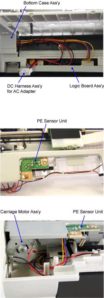
<Wiring of Logic Board Ass'y assembled in Bottom Case Ass'y>
(IV) Paper feed motor ass'y wiring
(V) Carriage motor ass'y and PE sensor harness wiring
1 - 12
Download Service Manual And Resetter Printer at http://printer1.blogspot.com
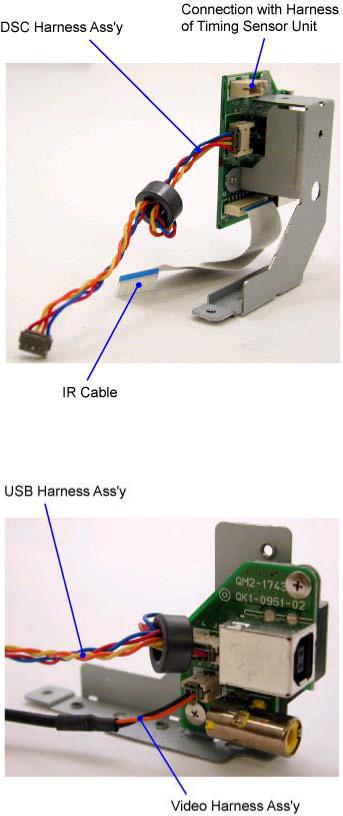
(VI) Front I/F unit wiring
(VII) Rear I/F unit wiring
To the top
 <Part 1: 3. REPAIR, 3-2, (1)>
1 - 13
Download Service Manual And Resetter Printer at http://printer1.blogspot.com
(2) Notes on disassembly and re-assembly
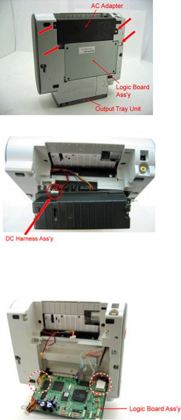
zAC adapter and logic board ass'y removal
1)Remove the 4 screws indicated by the arrow in the figure below. Position the DS700 so that it stands on the output tray unit, as shown below, to facilitate servicing.
2) Remove the DC harness ass'y, and AC adapter.
3)Remove the harnesses and cables from the logic board ass'y, leaving J402 and J501 on the left side and J601, J403, and J302 on the right side connected so that further work can be done easily.
Note: For removal of harnesses or cables with few pins, use a pair of tweezers to avoid damaging the connectors.
1 - 14
Download Service Manual And Resetter Printer at http://printer1.blogspot.com
4) Hold the logic board ass'y in a horizontal position, and slide it to the left to release the hook on the right side.
5)Pull and slide the right side of the logic board ass'y to the right, to release the hook on the left side. Then, remove the remaining harnesses and cables from the logic board ass'y.
Note: For removal of harnesses or cables with few pins, use a pair of tweezers to avoid damaging the connectors.
zOutput tray unit removal
1)Push the left and right sides of the paper output tray inward to release the hooks.
2)Pull the left side of the paper support outward to release the hook.
1 - 15
Download Service Manual And Resetter Printer at http://printer1.blogspot.com

zSide cover R ass'y removal
Remove the screw from the bottom case.
zSide cover L removal
Remove the screw from the bottom case.
zMain cover unit removal
Remove 2 screws from the left side and 2 screws from the right side.
<Right Side> |
<Left Side> |
1 - 16
Download Service Manual And Resetter Printer at http://printer1.blogspot.com
Loading...