


/PERATORgS -ANUALgFOR
, 5!23 5LTRA
3ERIES
#OMMERCIAL 7HEELCHAIRE,IFTS
|
¤ |
0ROVIDING !CCESSNTO THE 7ORLD ¤ |
|
)NTERNATIONALA#ORPORATEA(DQRS O 0 / O"OXA E |
7INAMAC S). 53! |
4(% ,)&4 ( % |
&!8 |
:$51,1* |
2SHU |
0DQ DWRUV |
XDO |
5HDG PDQXDO |
EHIRUH RSHUDWLQJ |
OLIW )DLOXUH WR GR |
VR PD\ UHVXOW LQ |
VHULRXV ERGLO\ |
LQMXU\ DQG RU |
SURSHUW\ GDPDJH |
.HHS PDQXDO LQ |
OLIW VWRUDJH SRXFK |
|
-ARCH |

Congratulations
We at The Braun Corporation wish to express our fullest appreciation on your new purchase. With you in mind, our skilled craftsmen have designed and assembled the finest lift available.
This manual includes safety precautions, lift operating instructions, manual operating instructions, and instructions for maintenance and lubrication procedures.
Your lift is built for dependability, and will bring you years of pleasure and independence, as long as maintenance is performed regularly and the lift is operated by an instructed person.
Sincerely,
THE BRAUN CORPORATION
Ralph W. Braun
Chief Executive Officer

Contents
Lift Terminology |
|
Lift Terminology Illustration ........................................ |
2 |
Introduction ................................................................ |
3 |
Direction ..................................................................... |
3 |
Lift Components ...................................................... |
4-6 |
Lift Actions and Functions ...................................... |
6, 7 |
Lift Operation Safety |
|
Safety Symbols .......................................................... |
8 |
Lift Operation Safety Precautions ......................... |
9-12 |
Pre-Lift Operation Notes and Details |
|
Lift Access Doors and Lift Interlocks ........................ |
13 |
General Safety ......................................................... |
14 |
Lift Control Switches ................................................ |
14 |
Lift Features |
|
Unfold and Fold ........................................... |
15, 16 |
Bridge Plate ................................................. |
16, 17 |
Inboard Roll Stop .............................................. |
17 |
Automatic Outboard Roll Stop ..................... |
17, 18 |
Roll Stop Latch .................................................. |
18 |
Outboard Roll Stop and Roll Stop Latch |
|
Operation ..................................................... |
19, 20 |
Handrails ........................................................... |
20 |
Lift Passengers |
|
Passenger Orientation (Boarding |
|
Direction) ..................................................... |
20, 21 |
Standees ........................................................... |
21 |
Yellow Boundaries ............................................. |
21 |
Floor Level Positioning ...................................... |
22 |
Vehicle (Floor Level) Loading and |
|
Unloading .................................................... |
22, 23 |
Wheelchair-Equipped Occupant Seat Belts ............. |
24 |
Operation Procedure Review ............................. |
24, 25 |
Preventive Maintenance ........................................... |
25 |
Lift Operating Instructions ............................... |
26-30 |
Manual Operating Instructions ........................ |
31-40 |
Decals and Antiskid .......................................... |
41-43 |
Maintenance and Lubrication ......................... |
44, 45 |
Warranty/Registration Instructions ...................... |
46 |
Page 1

Lift Terminology Illustration
“Bolt-on” Upright(2) |
c.HorseshoeTube |
HandPumpHandle |
StrikerBack |
AdjustableQuiet-RideBumper |
Gussets(2) |
BridgePlateEnds(2) |
Whale |
BridgePlateFlap |
InboardRollStop(L211 Seriesliftmodelsonly) |
DualHandrails (standardonL211 Seriesliftmodels) |
Adjustable HandrailStop |
Platform |
RollStop Latch |
AutomaticOutboard |
ActuatorHorseshoe |
Manual(a,bandc) |
Release |
Handle |
Handle |
PinDetent |
b.Cylinder Actuator |
-Quick |
Release |
Pin Base |
Plate |
Held-Hand |
Attendant's |
BoxControl |
Pump |
Module |
Slide |
Tubes |
HairpinActuator |
(Top)Cotter |
(inside)Cylinder |
visible)not( |
HairpinActuator |
(Bottom)Cotter |
Whale(Powered) |
PlatformPickup |
(fold)Bearings(2) |
|
FoldElectric |
Actuator |
||||||||||||||||||||||||||
|
|
|
Header |
|
|
Channel |
|
|
|
|
|
|
|
|
|
|
|
|
|
|
|
|
|
|
|
|
|
|
|
|
a. |
|
|
|
|
|
|
|
|
|
|
|
|
|
|
|
|
|
|
|
|
|
|
|
|
(ARS) |
|
|
RollStop |
SidePlate YellowBoundary (EdgeLiner-2) |
|
PlatformSide Plate(2) |
Adjustable |
HandrailStop |
Inboard Right(Front) |
Left(Rear) Outboard |
Asviewedfrom outsidethevehicle |
Page 2

Introduction
L200UARS Series lifts are commercial oriented (intended for operation by an attendant). The L200UARS Lift Series includes many standard lift models that vary in height and width. A standard L211UARS Series lift model is depicted in the Lift Terminology Illustration. Lift model numbers indicate lift dimensions. Model numbers of special order (nonstandard) lifts include other identification information exclusive to specific applications.
Lift operation procedures are the same for all L200UARS Series lift models. The operating instructions contained in this manual and posted on the lift address the
Lift Terminology
lift control switches and the corresponding lift functions only. Instructions are provided for manual operation of the lift in event of power or equipment failure.
L200UARS Series lifts are installed in various types of transit vehicles with varying lift access door configurations. The attendant must become familiar with the proper operation of the lift as well as the vehicle lift door system and the lift interlock system (if equipped). It is the responsibility of the lift operator (attendant) to properly open, secure and close the vehicle lift door(s), to activate the lift interlock (if equipped), to load and unload the wheelchair passenger (or standee) on and off the
platform, and to properly activate all lift functions.
Terminology: Become familiar with the terminology that will be used throughout this manual.
Become familiar with the identification of lift components and their functions. Contact your lift sales representative or call The Braun Corporation at 1-800-THE LIFT if any of this information is not fully understood.
Direction: The terms "left (rear)," "right (front)," "inboard," and "outboard" will be used throughout this manual to indicate direction (as viewed from outside the vehicle looking directly at the lift). Refer to the Lift Terminology Illustrations for clarification of direction terms.
Page 3

Lift Components
Refer to the Lift Terminology Illustration on page 2.
Lift Frame (Base Plate and Upright Assembly): The main lift frame consists of the base plate weldment (with two gussets), two bolt-on uprights, the striker back assembly, the bridge plate flap and two folding whales. The base plate and upright assembly supports the horseshoe and platform assembly. The rod end (bottom) of the electric fold actuator is mounted to the left side (rear) whale.
Bridge Plate: The bridge plate assembly consists of the striker back and the bridge plate flap.
The independent hinged bridge
Lift Terminology
plate flap bridges the gap between the lift platform and the vehicle floor when the platform is positioned at floor level.
The bridge plate travels from the stowed position to the bridging (horizontal) position as the lift platform unfolds and vice versa. Photos and further details regarding operation of the bridge plate are provided in the Pre-Lift Operation Notes section (page 16).
Whales: L200UARS Series lifts are equipped with two folding whales. The jaws of the whales engage the platform pickup bearings to fold and unfold the platform (one bearing located on each side of the platform). The rod end (bottom) of the electric fold actuator is mounted to the left
(rear) whale to power the fold and unfold functions. The right side (front) whale and bearing keep the lift in alignment (unison).
Horseshoe: The lift horseshoe is the U-shaped metal frame consisting of the header (top crossmember), the cylinder channel on the left and the horseshoe tube on the right. The horseshoe contains and protects the platform slide tube assembly, the hydraulic cylinder and the lifting chain assemblies. The pump module is mounted to the inboard face of the cylinder channel. The motor end (top) of the electric fold actuator is mounted to the outboard face of the cylinder channel. The horseshoe pivots on two shoulder bolts as the lift unfolds and folds.
Page 4
Pump Module: The lift-mounted pump module consists of the hydraulic pump, the manual hand pump and electrical components that power the lift electric/hydraulic systems.
Hand-held Control Switchbox:
The hand-held control switchbox is connected to the pump module. The control box is equipped with two color-coded rocker switches labeled UNFOLD (Out), FOLD (In), UP and DOWN. The switches activate the powered lift functions. Details regarding the control switches and their functions are provided in the Pre-Lift Operation Notes section (page 14).
Fold Actuator: The electric motor-driven actuator unfolds
Lift Terminology
and folds the platform when the UNFOLD (Out)/FOLD (In) switch is activated. The platform must be in the fully-raised position before the platform can be unfolded or folded. Further details in the Pre-Lift operation section (pages 15 and 16).
Slide Tube Assembly: The slide tube assembly carries the platform assembly as it lowers and raises. The slide tube assembly consists of two telescoping slide tubes connected to chain assemblies that travel up and down inside the horseshoe, the bottom support crossbar and two platform mounting plates.
Platform Assembly: The lift platform carries the wheelchair passenger (or standee) up and
down from ground level to the vehicle floor. The lift platform assembly consists of the frame with grating surface upon which the wheelchair is positioned, the inboard roll stop (L211UARS lift models), the outboard roll stop and the handrails (if equipped).
Dual Handrails: Dual handrails are provided for wheelchair passenger (or standee) use (standard on L211 Series lift models). The handrails are mounted on the platform and pivot as the lift unfolds and folds.
Outboard Roll Stop: The outboard roll stop is the automatic chain-driven outer barrier that provides a ramp for wheelchair loading and unloading at ground level. Photos and further
Page 5
Lift Components (continued)
details regarding the outboard roll stop are provided in the Pre-Lift Operation Notes section (pages 17-20).
Roll Stop Latch: The springloaded latch locks the outboard roll stop in the vertical position when the platform raises above ground level.
Inboard Roll Stop: L211UARS platforms are equipped with a fixed inboard roll stop. Attendant operation is not required for operation.
Manual Operation Systems:
Manual operation systems are provided for use in event of power or equipment failure.
Lift Terminology
L200UARS Series lifts are equipped with an “over-center” fold actuator manual release system to allow the lift platform to be manually unfolded and folded. A manual back-up hand pump is built into the pump module. The lift platform can be lowered and raised using the hand pump. Complete details and manual operating procedures are provided on pages 31-40.
Lift Actions and Functions
UNFOLD (Out) - Platform Unfold: Unfold is the action of the platform rotating out and down from the fully-stowed (vertical) position to the fullyunfolded (horizontal) position when the UNFOLD (Out) switch is pressed.
DOWN - Platform Lower: Down is the action of the platform lowering when the DOWN switch is pressed. When the platform is unfolded from the stow position, the platform must be lowered from the fully-raised position to the floor level position when unloading a passenger at floor level. The lift operator (attendant) must stop the platform at floor level (release DOWN switch). The platform is then lowered to ground level (fullylowered) to unload and/or load passengers.
DOWN - Roll Stop Unfold (Deploy): When the platform reaches the fully-lowered (ground level) position and the DOWN switch is continually pressed, the outboard roll stop rotates down
Page 6
ward from the vertical position to the ramp position.
UP - Roll Stop Fold (Raise):
When the platform is fully-lowered and the roll stop is in the ramp position, pressing the UP switch first rotates the roll stop upward from the ramp position to the vertical position.
UP - Platform Raise: Up is the action of the platform raising when the UP switch is pressed. The platform must be raised to and stopped at floor level when a wheelchair passenger (or standee) is entering or exiting the vehicle. The platform then must be raised fully (above floor level)
Lift Terminology
before the lift can be folded (stowed).
Stow Position: The lift is stowed when the platform has been fully raised and platform has been folded fully (vertical position).
Floor Level: Floor level is the position (height) the platform must be positioned in order for the wheelchair passenger (or standee) to enter and exit the vehicle. The platform must be positioned such that there is a smooth and level transition between the platform, bridge plate and vehicle floor. The platform must be positioned (lowered or raised), and stopped at floor level by the lift operator
(attendant).
Deploy: Lift deployment is the action of the platform unfolding, the platform lowering to ground level and the outboard roll stop unfolding to the ramp position.
Stow: Stow is the action of the outboard roll stop folding (raising) to the vertical position, the platform raising to the fully-raised position and the platform folding to the stowed (vertical) position.
Note: Further details regarding lift control switches and the corresponding lift functions are provided in the Pre-Lift Operating Notes section.
Page 7
Lift Operation Safety
Safety Symbols
SAFETY FIRST! Know That....
AAll information contained in this manual and
supplements (if included), is provided for your safety. Familiarity with proper operation instructions as well as proper maintenance procedures are necessary to ensure safe, troublefree operation. Safety precautions are provided to identify potentially hazardous situations and provide instruction on how to avoid them.
B |
|
|
|
|
|
C |
|
|
|
|
|
|
WARNING |
|
|
|
|
CAUTION |
|
||
|
|
|
|
|
|
|
|
|
|
|
|
|
|
This symbol indicates |
|
|
|
|
|
This symbol indicates |
|
|
|
|
important safety |
|
|
|
|
|
important information |
|
|
|
|
information regarding |
|
|
|
|
|
regarding how to |
|
|
|
|
a potentially hazard- |
|
|
|
|
|
avoid a hazardous |
|
|
|
|
ous situation that |
|
|
|
|
|
situation that could |
|
|
|
|
could result in serious |
|
|
|
|
|
result in minor per- |
|
|
|
|
bodily injury and/or |
|
|
|
|
|
sonal injury or prop- |
|
|
|
|
property damage. |
|
|
|
|
|
erty damage. |
|
|
|
|
|
|
|
|
|
|
|
|
|
|
|
|
|
|
|
|
|
|
|
D Note: Additional information provided to help clarify or detail a specific subject.
These symbols will appear throughout this manual as well as on the labels posted on your lift. Recognize the seriousness of this information.
Page 8
Lift Operation Safety
Lift Operation Safety Precautions
 WARNING Read manual and supplement(s) before operating lift. Read and become familiar with all safety precautions, pre-lift operation notes and details, operating instructions and manual operating instructions before operating the lift.
 WARNING Load and unload on level surface only.
 WARNING Engage vehicle parking brake before operating lift.
 WARNING Provide adequate clearance outside the vehicle to accommodate the lift before opening lift door(s) or operating lift.
 WARNING Load and unload clear of vehicular traffic.
 WARNING Open lift door(s) fully and secure before operating lift.
 WARNING Inspect lift before operation. Do not operate lift if you suspect lift damage, wear or any abnormal condition.
 WARNING Keep operator and bystanders clear of area in which the lift operates.
 WARNING Lift attendants must ensure that lift occupants keep hands, arms and all other body parts within the lift occupant area and clear of moving parts.
Page 9

Lift Operation Safety
Lift Operation Safety Precautions (continued)
 WARNING
 WARNING
 WARNING
Platform must be positioned at floor level (bridge plate height) when loading or unloading in and out of vehicle.
The wheelchair-equipped torso restraint belt must be properly positioned and engaged before loading onto the wheelchair lift platform.
Do not use the outboard roll stop as a barrier (brake). Stop and brake wheelchair when loading onto the platform (manually stop and brake manual wheelchairs — stop powered wheelchairs with the wheelchair controls).
 WARNING Turn powered (electric) wheelchairs off when on lift platform.
 WARNING Press the DOWN switch until the entire platform rests on ground level (lowered fully) and the outboard roll stop is fully unfolded (ramp position) before loading or unloading a passenger at ground level.
 WARNING Outboard platform roll stop must be fully unfolded (ramp position) until the entire wheelchair (or standee) crosses roll stop when loading or unloading at ground level.
 WARNING Do not overload or abuse. The load rating applies to both the raising and lowering functions - continuous lifting capacity is 800 lbs.
 WARNING Do not operate or board your lift if you or your lift operator are intoxicated.
Page 10

Lift Operation Safety
 WARNING Whenever a wheelchair passenger (or standee) is on the platform, the:
•Passenger must be positioned fully inside yellow boundaries
•Wheelchair brakes must be locked
•Roll stop(s) must be UP
•Roll stop latch must be fully engaged
•Passenger must grip both handrails (if able)
 WARNING Passenger must lower head to clear door jamb header when loading or unloading at vehicle floor level.
 WARNING Platform must be fully UP before pressing FOLD/UNFOLD (In/Out) switch.
 WARNING Accidental activation of control switch(es) may cause unintended operation(s).
 WARNING When performing manual unfold procedures, have an assistant support the platform before pulling actuator quick-release pin.
 WARNING Maintenance and lubrication procedures must be performed as specified in this manual by authorized (certified) service personnel.
Page 11

Lift Operation Safety
Lift Operation Safety Precautions (continued)
 WARNING Replace missing, worn or illegible decals.
 WARNING Keep this lift operator's manual in lift-mounted manual storage pouch when not in use.
 WARNING Never modify (alter) a Braun Corporation lift.
 WARNING Do not use accessory devices not authorized by The Braun Corporation.
 WARNING Do not remove any guards or covers.
 WARNING Keep clear of any hydraulic leak.
 WARNING Failure to follow these safety precautions may result in serious bodily injury and/or property damage.
Page 12

Pre-Lift Operation Notes and Details
 WARNING
Read and become familiar with all lift operation safety precautions, pre-lift operation notes and details, operating instructions and manual operating instructions prior to operating the lift. If this information is not fully understood, contact The Braun Corporation immediately. Failure to do so may result in serious bodily injury and/or property damage.
L200UARS Series lift models are specifically designed to be operated by an attendant. The Lift Operating Instructions contained in this manual and posted on the lift provide instructions for operation of the lift only. Read and become familiar with all lift operation safety precautions, prelift operation notes and details, operating instructions and manual operating instructions before attempting lift operation procedures.
Lift Access Doors and Lift Interlocks: Attendants must become familiar with the vehicle lift access door system and the interlock system (if equipped), as well as the proper operation of the lift. Transit vehicles and lift access door configurations vary.
Door securement devices (latches, hooks, cables, etc.) and procedures to operate them vary as well.
Lift interlocks are required by nearly all transit authorities. Instructions for operation of interlocks and door securement systems cannot be addressed in this manual or on lift-posted operating instructions decals due to the variety of procedures required for operating them.
It is the responsibility of the lift operator (attendant) to properly open, secure and close the vehicle lift door(s), to activate the lift interlock (if equipped), to load and unload the wheelchair passenger (or standee) on and off the lift platform, and to properly
Page 13
Pre-Lift Operation Notes and Details
activate all lift functions.
General Safety: The lift operator (attendant) and bystanders must
keep clear of the area in which the lift operates and clear of all moving parts. Lift attendants must ensure that lift occupants
(passengers) keep hands, arms and all other body parts within the lift occupant area and clear of moving parts.
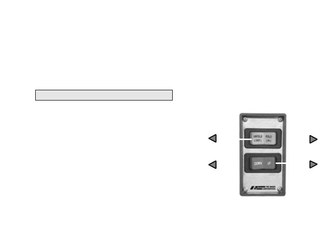
Lift Control Switches
The hand-held attendant’s control box provides an orange UNFOLD/FOLD (Out/In) switch and a red DOWN/UP switch. The control switches are color-coded to correspond to the color coding and switch function labels that appear on the lift-posted operating instructions decal.
Triangular-shaped color-coded symbols ( ) appear on the lift operating instructions decal. The color of the symbol corresponds to the color of the corresponding switch. The direction (point) of the symbol corresponds with the direction the switch should be activated (pressed) to produce the intended lift function.
|
Orange UNFOLD/FOLD Switch |
|
||||||
Press |
|
|
|
|
|
|
|
Press |
|
|
|
|
|
|
|
||
switch |
|
|
|
|
|
|
|
switch |
left for |
|
|
|
|
|
|
|
right for |
UNFOLD |
|
|
|
|
|
|
|
FOLD |
|
|
|
|
|
|
|||
(Out) |
|
|
|
|
|
|
|
(In) |
Press |
|
|
|
|
|
|
|
Press |
|
|
|
|
|
|
|||
switch |
|
|
|
|
|
|
|
switch |
left for |
|
|
|
|
|
|
|
right for |
DOWN |
|
|
|
|
|
|
|
UP |
(To Lower) |
|
|
|
|
|
|
|
(To Raise) |
|
|
|
|
|
|
|
|
|
|
|
|
|
|
|
|
||
|
|
|
Red DOWN/UP Switch |
|
|
|||
|
|
|
|
|
|
|
|
|
Page 14
 Loading...