


AT-FS750/24POE
Table of contents
 Loading...
Fast Ethernet
WebSmart Switch
AT-FS750/24POE
Installation Guide
613-001269 Rev. A

Copyright © 2010 Allied Telesis, Inc.
All rights reserved. No part of this publication may be reproduced without prior written permission from Allied Telesis, Inc.
Allied Telesis and the Allied Telesis logo are trademarks of Allied Telesis, Incorporated. All other product names, company names, logos or
other designations mentioned herein are trademarks or registered trademarks of their respective owners.
Allied Telesis, Inc. reserves the right to make changes in specifications and other information contained in this document without prior
written notice. The information provided herein is subject to change without notice. In no event shall Allied Telesis, Inc.be liable for any
incidental, special, indirect, or consequential damages whatsoever, including but not limited to lost profits, arising out of or related to this
manual or the information contained herein, even if Allied Telesis, Inc. has been advised of, known, or should have known, the possibility of
such damages.

Electrical Safety and Emissions Standards
This product meets the following standards.
U.S. Federal Communications Commission
Radiated Energy
Note: This equipment has been tested and found to comply with the limits for a Class A digital device pursuant to Part 15
of FCC Rules. These limits are designed to provide reasonable protection against harmful interference when the
equipment is operated in a commercial environment. This equipment generates, uses, and can radiate radio frequency
energy and, if not installed and used in accordance with this instruction manual, may cause harmful interference to radio
communications. Operation of this equipment in a residential area is likely to cause harmful interference in which case
the user will be required to correct the interference at his own expense.
Note: Modifications or changes not expressly approved of by the manufacturer or the FCC, can void your right to operate
this equipment.
Industry Canada
This Class A digital apparatus complies with Canadian ICES-003.
Cet appareil numérique de la classe A est conforme à la norme NMB-003 du Canada.
RFI Emissions FCC Class A, EN55022 Class A, CISPR Class A, C-TICK, CE
Warning: In a domestic environment this product may cause radio interference in
which case the user may be required to take adequate measures.
Immunity EN55024
Electrical Safety EN60950-1 (TUV), UL 60950-1 (
CULUS
)
Laser Safety EN60825
3

Translated Safety Statements
Important: The indicates that a translation of the safety statement is available in a PDF
document titled “Translated Safety Statements” on our web site.
Go to http://www.alliedtelesis.com/support/software
and this product under Product Name. You can view this document online or download it onto a local
workstation or server.
. Select “Switches” under Product Category
4

Contents
Preface................................................................................................................................................................................ 11
Safety Symbols Used in this Document................................................................................................................................12
Where to Find Web-based Guides .......................................................................................................................................13
Contacting Allied Telesis ......................................................................................................................................................14
Online Support ..............................................................................................................................................................14
Email and Telephone Support .......................................................................................................................................14
Warranty........................................................................................................................................................................14
Returning Products........................................................................................................................................................14
For Sales or Corporate Information...............................................................................................................................14
Management Software Updates ...........................................................................................................................................15
Chapter 1: Overview ..........................................................................................................................................................17
Features ...............................................................................................................................................................................18
Front and Back Panels .........................................................................................................................................................19
Ports .....................................................................................................................................................................................20
Twisted Pair Ports .........................................................................................................................................................20
Uplink Combo Ports ......................................................................................................................................................20
Eco-friendly Switch ...............................................................................................................................................................21
LEDs.....................................................................................................................................................................................22
System LEDs.................................................................................................................................................................22
10/100Base-T POE Port LEDs......................................................................................................................................23
10/100Base-T Non-POE Port LEDs ..............................................................................................................................24
Uplink Combo Port LEDs ..............................................................................................................................................25
Power Supply .......................................................................................................................................................................26
Power over Ethernet.............................................................................................................................................................27
Power Budgeting ...........................................................................................................................................................27
Implementation..............................................................................................................................................................28
Ethernet Switching Basics ....................................................................................................................................................29
MAC Address Table ......................................................................................................................................................29
Duplex Mode ....................................................................................................................
Store and Forward.........................................................................................................................................................30
Back Pressure and Flow Control...................................................................................................................................30
.............................................30
Chapter 2: Installation .......................................................................................................................................................33
Reviewing Safety Precautions..............................................................................................................................................34
Selecting a Site for the Switch..............................................................................................................................................37
Cable Specifications .............................................................................................................................................................38
Twisted Pair Ports .........................................................................................................................................................38
SFP Ports ......................................................................................................................................................................38
Unpacking the Switch ...........................................................................................................................................................39
Installing the Switch on a Desktop ........................................................................................................................................40
Installing the Switch on a Wall ..............................................................................................................................................41
Installing a Switch in a Rack .................................................................................................................................................44
Installing an SFP Transceiver...............................................................................................................................................46
Cabling and Powering On the Switch ...................................................................................................................................48
Connecting the Twisted Pair Cables .............................................................................................................................48
Connecting the Fiber Optic Cables ...............................................................................................................................49
Powering On the Switch ................................................................................................................................................50
Starting a Management Session ..........................................................................................................................................52
Chapter 3: Troubleshooting ..............................................................................................................................................53
5

Contents
Appendix A: Technical Specifications .............................................................................................................................55
Physical Specifications .........................................................................................................................................................55
Environmental Specifications................................................................................................................................................55
Power Specifications.............................................................................................................................................................55
Safety and Electromagnetic Emissions Certifications...........................................................................................................56
Connectors and Port Pinouts ................................................................................................................................................57
Appendix B: Cleaning Fiber Optic Connectors ...............................................................................................................59
Using a Cartridge-Type Cleaner ...........................................................................................................................................60
Using a Swab........................................................................................................................................................................62
6

List of Figures
Figure 1: AT-FS750/24POE Front and Back Panels ........................................................................................................... 19
Figure 2: Eco-friendly Switch............................................................................................................................................... 21
Figure 3: System LEDs........................................................................................................................................................ 22
Figure 4: POE Port LEDs (Port 1 - 12) ................................................................................................................................ 23
Figure 5: 10/100Base-T Non-PoE Port LEDs (Port 13 - 24)................................................................................................ 24
Figure 6: Uplink Combo Port LEDs...................................................................................................................................... 25
Figure 7: Attaching the Rubber Feet ................................................................................................................................... 40
Figure 8: Attaching Brackets for Wall Mounting................................................................................................................... 41
Figure 9: Positioning and Drilling Holes for Wall Installation ............................................................................................... 42
Figure 10: Positioning the Switch onto the Wall with Mounting Screws .............................................................................. 43
Figure 11: Removing Feet from Switch ............................................................................................................................... 44
Figure 12: Attaching the Rack-Mount Bracket ..................................................................................................................... 44
Figure 13: Mounting the Switch on the Rack ....................................................................................................................... 45
Figure 14: Removing the Dust Plug from the SFP Slot ....................................................................................................... 46
Figure 15: Inserting the SFP................................................................................................................................................ 47
Figure 16: Connecting the Twisted Pair Data Cables.......................................................................................................... 48
Figure 17: Removing the Dust Plug from the SFP transceiver ............................................................................................ 49
Figure 18: Connecting the Fiber Optic Cable ...................................................................................................................... 50
Figure 19: Plugging in the AC Power Cord.......................................................................................................................... 50
Figure 20: AT-S105 Management Software Main Page ...................................................................................................... 52
Figure 21: RJ-45 Connector and Port Pin Layout................................................................................................................ 57
Figure 22: Ferrule in an SC Connector Plug........................................................................................................................ 59
Figure 23: Unclean and Clean Ferrule................................................................................................................................. 59
Figure 24: Cartridge Cleaner ............................................................................................................................................... 60
Figure 25: Rubbing the Ferrule Tip on the Cleaning Surface .............................................................................................. 60
Figure 26: Lint-Free and Alcohol-Free Swabs..................................................................................................................... 62
Figure 27: Cleaning a Recessed Ferrule............................................................................................................................. 62
7

List of Figures
8

List of Tables
Table 1. Safety Symbols .....................................................................................................................................................12
Table 2. Eco-friendly Switch Functions ...............................................................................................................................21
Table 3. System LEDs ........................................................................................................................................................22
Table 4. 10/100Base-T POE Port LEDs (Ports 1 - 12) .......................................................................................................23
Table 5. 10/100Base-T Non-PoE Port LEDs (Port 13 - 24) Description .............................................................................24
Table 6. Uplink Combo Port LEDs Description ...................................................................................................................25
Table 7. IEEE 802.3af Class vs. Power Levels ..................................................................................................................28
Table 8. Twisted Pair Cabling and Distances .....................................................................................................................38
Table 9. MDI Pin Signals (10Base-T or 100Base-TX) ........................................................................................................57
Table 10. MDI-X Pin Signals (10Base-T or 100Base-TX) ..................................................................................................57
Table 11. RJ-45 1000Base-T Connector Pinouts ...............................................................................................................58
9

List of Tables
10

Preface
This guide provides the hardware installation instructions for your
AT-FS750/24POE Fast Ethernet WebSmart Switch as well as how to start
a management session with the AT-S105 management software. This
preface contains the following sections:
“Safety Symbols Used in this Document” on page 12
“Where to Find Web-based Guides” on page 13
“Contacting Allied Telesis” on page 14
“Management Software Updates” on page 15
11
Preface
Safety Symbols Used in this Document
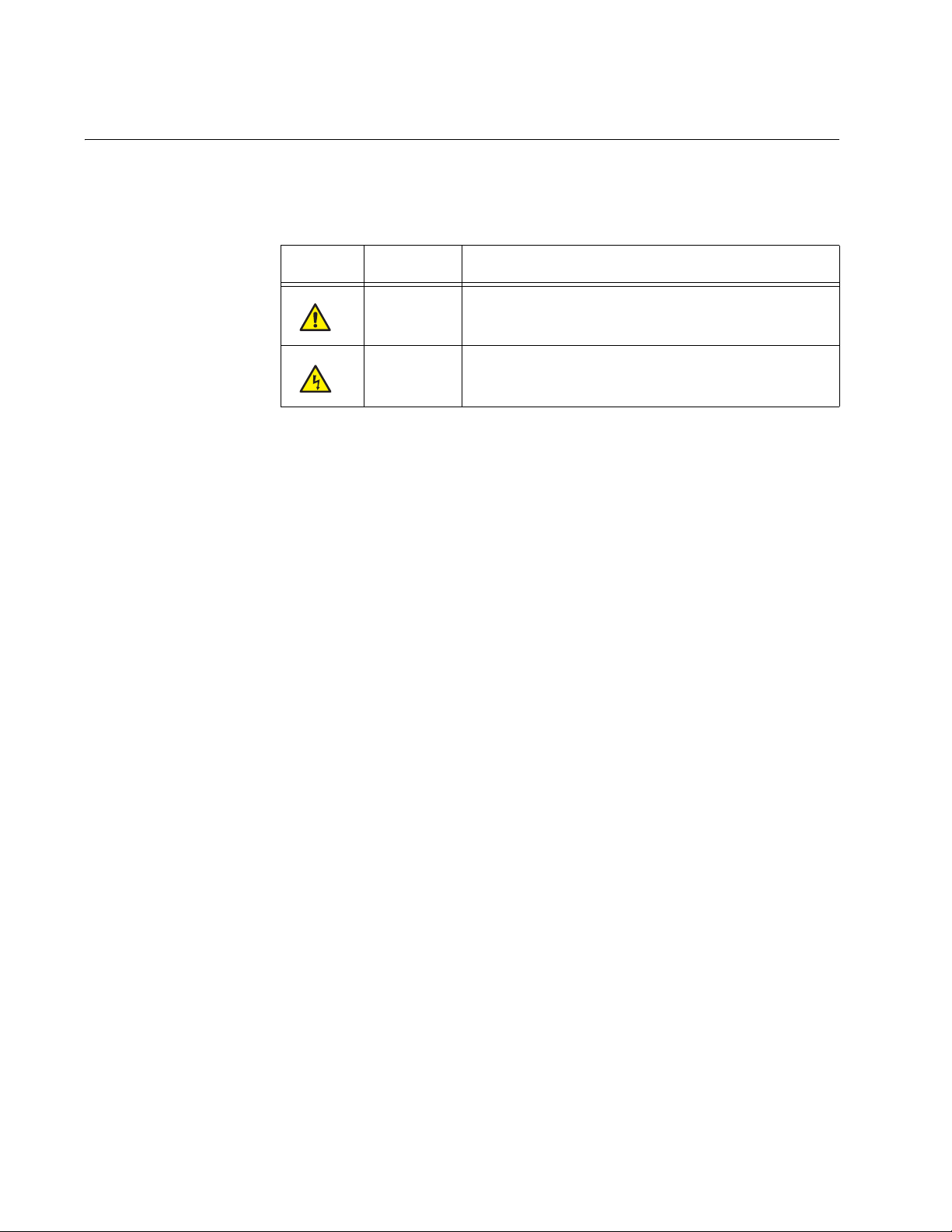
This document uses the safety symbols defined in Table 1.
Table 1. Safety Symbols
Symbol Meaning Description
Caution Performing or omitting a specific action may
result in equipment damage or loss of data.
Warning Performing or omitting a specific action may
result in electrical shock.
12

Where to Find Web-based Guides
The installation and user guides for all Allied Telesis products are available
in portable document form (PDF) on our web site.
AT-FS750/24POE Fast Ethernet WebSmart Switch Installation Guide
Go to http://www.alliedtelesis.com/support/software
model number of your product in the “Search by Product” field. You can
view the documents online or download them onto a local workstation or
server.
and enter the
13

Preface
Contacting Allied Telesis
This section provides Allied Telesis contact information for technical
support as well as sales or corporate information.
Online Support You can request technical support online by accessing the Allied Telesis
Knowledge Base from the following web site:
www.alliedtelesis.com/support. You can use the Knowledge Base to
submit questions to our technical support staff and review answers to
previously asked questions.
Email and
Telephone
Support
For Technical Support via email or telephone, refer to the Allied Telesis
web site: www.alliedtelesis.com. Select your country from the list
displayed on the website. Then select the appropriate menu tab.
Warranty For the AT-FS750/24POE Fast Ethernet WebSmart Switch hardware
warranty information, refer to the Allied Telesis web site at
www.alliedtelesis.com/warranty.
Returning
Products
For Sales or
Corporate
Products for return or repair must first be assigned a Return Materials
Authorization (RMA) number. A product sent to Allied Telesis without a
RMA number will be returned to the sender at the sender’s expense. For
instructions on how to obtain an RMA number, go to the Support section
on our web site at www.alliedtelesis.com.
You can contact Allied Telesis for sales or corporate information at our
web site: www.alliedtelesis.com. Select your country from the list
displayed on the website. Then select the appropriate menu tab.
Information
14

Management Software Updates
New releases of management software for our managed products are
available from either of the following Internet sites:
Allied Telesis web site: www.alliedtelesis.com
Allied Telesis FTP server: ftp://ftp.alliedtelesis.com
If you prefer to download new software from the Allied Telesis FTP server
from your workstation’s command prompt, you will need FTP client
software and you must log in to the server. Enter “anonymous” for the user
name and your email address for the password.
AT-FS750/24POE Fast Ethernet WebSmart Switch Installation Guide
15

Preface
16

Chapter 1
Overview
The AT-FS750/24POE Fast Ethernet WebSmart Switch is designed to
simplify the task of creating or expanding an Ethernet or Fast Ethernet
network.
This chapter contains the follows sections:
“Features” on page 18
“Front and Back Panels” on page 19
“Ports” on page 20
“Eco-friendly Switch” on page 21
“LEDs” on page 22
“Power Supply” on page 26
“Power over Ethernet” on page 27
“Ethernet Switching Basics” on page 29
17

Chapter 1: Overview
Features
The features of the AT-FS750/24POE Fast Ethernet WebSmart Switch
include:
24 Auto-Negotiating 10/100Base-T twisted pair ports with RJ-45
connectors
Two uplink combo ports that consist of two 10/100/1000Base-T twisted
pair ports and two Gigabit small form-factor pluggable (SFP) ports
Store and Forward switching supports line rates of:
– 1,480,000 pps (1000 MB/sec)
– 148,000 pps (100 MB/sec)
– 14,800 pps (10 MB/sec)
Non-Blocking Full-Wire speed switching on all packet sizes
MAC address table capacity of up to 8K addresses with automatic
aging
IEEE 802, IEEE 802.3u, and IEEE802.3z
IEEE 802.3af POE compliant on ports 1 - 12 (Alternative A)
IEEE 802.3 and IEEE 802.3u compliant
IEEE 802.3x supports”
– Flow Control in full-duplex operation
– Back Pressure in half-duplex operation
– Auto MDI/MDI-X on all twisted pair ports
(including combo ports)
Eco-friendly switch for enabling/disabling port LEDs and for resetting
switch
Minimizes transmit signal power on each GE port based on the
specific cable length to the end point
Each port assumes low power mode when link goes down
Installation on desktop, mounted on the wall, and mounted in a 19”
rack.
Smart Fan with fan speed control, device acoustic noise less than
40dB
Front panel LEDs for unit and port status
Web-based configuration using the AT-S105 Management software
18
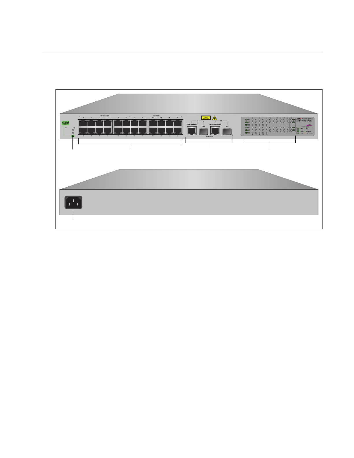
Front and Back Panels
10/100Base Twisted Pair Ports
Port LEDs
Uplink Combo Ports
System LEDs
eco-friendly Switch
AC Power
Figure 1 illustrates the front and back panels of the AT-FS750/24POE Fast
Ethernet WebSmart Switch.
SYSTEM
POWER
POE
AT-FS750/24POE Fast Ethernet WebSmart Switch Installation Guide
24 Port 10/100 Mbps WebSmart Switch
with 12 POE and 2 Combo SFP Ports
1714
50-60Hz
100-240VAC~
1715
Figure 1. AT-FS750/24POE Front and Back Panels
19

Chapter 1: Overview
Note
Ports
The AT-FS750/24POE Fast Ethernet WebSmart Switch features 24
twisted pair ports and two uplink combo ports. See the following sections
for more information:
“Twisted Pair Ports”
“Uplink Combo Ports”
Twisted Pair
Ports
The ports on the AT-FS750/24POE Fast Ethernet WebSmart Switch are
are capable of 10 megabits per second (Mbps) and 100 Mbps speeds and
are 10Base-T and 100Base-TX compliant.The twisted pair ports feature 8pin RJ-45 connectors. (For the port pinouts, refer to “Connectors and Port
Pinouts” on page 57.)
The ports are IEEE 802.3u Auto-Negotiation compliant. With AutoNegotiation, the switch automatically matches the highest possible
common speed between each switch port and each end node. For
example, if an end node is capable of only 10 Mbps, the switch sets the
port connected to the end node to 10 Mbps.
Each twisted pair port on the switch can operate in either half- or fullduplex mode. The twisted pair ports are IEEE 802.3u-compliant and AutoNegotiate the duplex mode setting.
For the switch to set the duplex mode for each port correctly, the
end nodes that you connect to the switch ports must be configured
for Auto-Negotiation. Otherwise, a duplex mode mismatch can
occur, affecting network performance. For further information, refer
to “Duplex Mode” on page 30.
Uplink Combo
Ports
Each twisted pair port has a maximum operating distance of 100 m
(328 feet). For 10 Mbps operation, Category 3 or better 100 ohm shielded
or unshielded twisted pair cabling is required. For 100 or 1000 Mbps
operation, Category 5 and Enhanced Category 5 (5E) 100 ohm shielded
or unshielded twisted pair cabling is required.
The twisted pair ports are auto-MDI. They automatically configure
themselves as either MDI or MDI-X, which allows you to use straight
through or crossover twisted pair cables to connect devices to the ports.
The two uplink combo ports (ports 49 and 50) consist of an SFP port and a
redundant twisted-pair port. The SFP ports support fiber optic connectivity
at 100FX and 1000 SX/LX, while the twisted pair ports support 10/100/
1000Base-T. If both ports of a combo pair are connected to the network,
traffic is switched through the SFP port and the corresponding twisted pair
port acts a redundant port in case of failure.
20
Loading...