

Default Login Details
User’s Guide
ARMOR G1
AC2600 Multi-Gigabit Security WiFi Router
Model: NBG6818
LAN IP Address http://zyxelwifi.com
OR
http://zyxelwifi.net
Version 1.00 Edition 2, 08/2020
Copyright © 2020 Zyxel Communications Corporation

IMPORTANT!
READ CAREFULLY BEFORE USE.
KEEP THIS GUIDE FOR FUTURE REFERENCE.
Screenshots and graphics in this book may differ slightly from your product due to differences in your
product firmware or your computer operating system. Every effort has been made to ensure that the
information in this manual is accurate.
Related Documentation
•Quick Start Guide
The Quick Start Guide shows how to connect the NBG6818 and access the Web Configurator wizards.
It contains information on setting up your network and configuring for Internet access.
•More Information
Go to support.zyxel.com to find other information on the NBG6818
.
NBG6818 User’s Guide
2
Document Conventions
Warnings and Notes
These are how warnings and notes are shown in this guide.
Warnings tell you about things that could harm you or your device.
Note: Notes tell you other important information (for example, other things you may need to
configure or helpful tips) or recommendations.
Syntax Conventions
• Product labels, screen names, field labels and field choices are all in bold font.
• A right angle bracket ( > ) within a screen name denotes a mouse click. For example, Setting >
Internet > Internet Connection means you first click Setting in the navigation panel, then the Internet
sub menu and finally the Internet Connection tab to get to that screen.
Icons Used in Figures
Figures in this user guide may use the following generic icons. The NBG6818 icon is not an exact
representation of your device.
NBG6818 Wireless Device Laptop Computer
Switch Firewall Server
Internet Desktop Computer Smartphone
NBG6818 User’s Guide
3

Contents Overview
Contents Overview
User’s Guide ......................................................................................................................................10
Introduction ........................................................................................................................................... 11
Wizard .................................................................................................................................................... 17
The Web Configurator ......................................................................................................................... 27
NBG6818 Modes ................................................................................................................................... 34
Standard Mode .................................................................................................................................... 36
................................................................................................................................................................ 38
Bridge Mode ......................................................................................................................................... 39
Tutorials .................................................................................................................................................. 42
Technical Reference ........................................................................................................................55
Applications .......................................................................................................................................... 56
WAN ....................................................................................................................................................... 77
Wireless LAN ........................................................................................................................................ 102
LAN ....................................................................................................................................................... 113
Security ................................................................................................................................................ 123
System .................................................................................................................................................. 130
Troubleshooting .................................................................................................................................. 141
NBG6818 User’s Guide
4

Table of Contents
Table of Contents
Document Conventions .................................................................. ....................................................3
Contents Overview .............................................................................................................................4
Table of Contents.................................................................................................................................5
Part I: User’s Guide.......................................................................................... 10
Chapter 1
Introduction ........................................................................................................................................11
1.1 Overview ......................................................................................................................................... 11
1.2 Applications .................................................................................................................................... 11
1.3 Ways to Manage the NBG6818 .................................................................................................... 12
1.4 Good Habits for Managing the NBG6818 ................................................................................... 12
1.5 Resetting the NBG6818 .................................................................................................................. 13
1.5.1 How to Use the RESET Button ................................................................................................ 13
1.6 The WPS Button ............................................................................................................................... 13
1.7 LEDs .................................................................................................................................................. 14
1.8 Desk Mounting ................................................................................................................................ 15
1.9 Wall Mounting ................................................................................................................................. 15
Chapter 2
Wizard .................................................................................................................................................17
2.1 Overview ......................................................................................................................................... 17
2.2 Accessing the Wizard ..................................................................................................................... 17
Chapter 3
The Web Configurator........................................................................................................................27
3.1 Overview ......................................................................................................................................... 27
3.2 Accessing the Web Configurator ................................................................................................. 27
3.3 Navigation Panel ............................................................................................................................ 29
3.3.1 Standard Mode Navigation Panel ...................................................................................... 30
3.3.2 Bridge Mode Navigation Panel ........................................................................................... 32
Chapter 4
NBG6818 Modes.......................................... ............................................ .... .......................................34
4.1 Overview ......................................................................................................................................... 34
4.2 Modes .............................................................................................................................................. 34
NBG6818 User’s Guide
5

Table of Contents
Chapter 5
Standard Mode..................................................................................................................................36
5.1 Overview ......................................................................................................................................... 36
5.2 What You Can Do .......................................................................................................................... 36
5.3 Standard Mode Status Screen ...................................................................................................... 36
.............................................................................................................................................................38
Chapter 6
Bridge Mode......................................... ... ............................................ .... ...........................................39
6.1 Overview ......................................................................................................................................... 39
6.2 What You Can Do .......................................................................................................................... 39
6.3 Setting your NBG6818 to Bridge Mode ........................................................................................39
6.3.1 Accessing the Web Configurator in Bridge Mode ............................................................ 40
6.4 Bridge Mode Status Screen ........................................................................................................... 41
Chapter 7
Tutorials...............................................................................................................................................42
7.1 Overview ......................................................................................................................................... 42
7.2 Run a Speed Test ............................................................................................................................ 42
7.3 Configure the NBG6818’s WiFi Networks ......................................................................................43
7.4 Enable or Disable a WiFi Network ................................................................................................. 45
7.5 Add Clients to a Profile .................................................................................................................. 46
7.6 Set a Profile’s WiFi Schedule .......................................................................................................... 47
7.7 Pause or Resume Internet Access on a Profile ............................................................................ 49
7.8 Turn on or off the NBG6818’s LED (Light) ...................................................................................... 50
7.9 Change Your NBG6818 Operating Mode ................................................................................... 51
7.10 Configure a Port Forwarding Rule .............................................................................................. 52
Part II: Technical Reference...........................................................................55
Chapter 8
Applications .......................................................................................................................................56
8.1 Overview ......................................................................................................................................... 56
8.1.1 What You Can Do ................................................................................................................. 56
8.1.2 What You Need To Know ..................................................................................................... 56
8.1.3 Before You Begin ................................................................................................................... 57
8.2 Parental Control ............................................................................................................................. 57
8.2.1 Device Screen ....................................................................................................................... 57
8.3 OpenVPN Server/Client ................................................................................................................. 61
8.3.1 OpenVPN Server Screen ...................................................................................................... 61
8.3.2 OpenVPN Account Screen .................................................................................................. 63
NBG6818 User’s Guide
6

Table of Contents
8.3.3 OpenVPN Client Screen ....................................................................................................... 65
8.4 USB Application .............................................................................................................................. 67
8.4.1 SAMBA Server Screen ........................................................................................................... 67
8.4.2 FTP Server Screen .................................................................................................................. 69
8.4.3 USB Media Sharing Screen ................................................................................................... 71
8.5 Access Your Shared Files From a Computer ............................................................................... 73
8.5.1 Using Windows Explorer ........................................................................................................ 73
8.5.2 Using FTP Program ................................................................................................................. 74
Chapter 9
WAN ....................................................................................................................................................77
9.1 Overview ......................................................................................................................................... 77
9.2 What You Can Do .......................................................................................................................... 77
9.3 What You Need To Know .............................................................................................................. 78
9.3.1 Configuring Your Internet Connection ............................................................................... 78
9.4 Internet Connection Screen .......................................................................................................... 79
9.4.1 IPoE Encapsulation ................................................................................................................ 79
9.4.2 PPPoE Encapsulation ............................................................................................................ 82
9.4.3 PPTP Encapsulation ............................................................................................................... 85
9.5 NAT & Port Forwarding Screen ...................................................................................................... 87
9.5.1 Add Port Forwarding Rule Screen ....................................................................................... 89
9.6 Passthrough Screen ........................................................................................................................ 91
9.7 Port Trigger Screen ......................................................................................................................... 92
9.7.1 Add Port Trigger Rule Screen ............................................................................................... 94
9.8 Dynamic DNS Screen ..................................................................................................................... 95
9.9 UPnP Screen .................................................................................................................................... 96
9.9.1 Turning On UPnP in Windows 7 Example ............................................................................ 97
9.9.2 Turning on UPnP in Windows 10 Example .......................................................................... 99
Chapter 10
Wireless LAN .....................................................................................................................................102
10.1 Overview ..................................................................................................................................... 102
10.1.1 What You Can Do ............................................................................................................. 102
10.1.2 What You Should Know ....................................................................................................103
10.2 Main WiFi Screen ........................................................................................................................ 106
10.3 Guest WiFi Screen ....................................................................................................................... 108
10.4 MAC Filter Screen ...................................................................................................................... 108
10.4.1 Add MAC Address Screen ............................................................................................... 109
10.5 WPS Screen ................................................................................................................................. 110
10.6 Scheduling Screen ..................................................................................................................... 112
Chapter 11
LAN....................................................................................................................................................113
NBG6818 User’s Guide
7

Table of Contents
11.1 Overview ..................................................................................................................................... 113
11.2 What You Can Do ...................................................................................................................... 113
11.3 What You Need To Know .......................................................................................................... 113
11.4 LAN IP Screen .............................................................................................................................. 114
11.4.1 Static DHCP Table-Add/Edit Rule Screen ....................................................................... 117
11.4.2 Configure LAN Screen in Bridge Mode .......................................................................... 119
11.5 IPv6 LAN Screen .......................................................................................................................... 120
Chapter 12
Security .............................................................................................................................................123
12.1 Overview ................................................................................................................................... 123
12.1.1 What You Can Do ............................................................................................................. 123
12.1.2 What You Need To Know ................................................................................................. 123
12.2 IPv4 Firewall Screen ................................................................................................................... 124
12.2.1 IPv4 Firewall-Add Rule Screen ......................................................................................... 126
12.3 IPv6 Firewall Screen .................................................................................................................... 127
12.3.1 IPv6 Firewall-Add Rule Screen ......................................................................................... 128
Chapter 13
System...............................................................................................................................................130
13.1 Overview ..................................................................................................................................... 130
13.2 What You Can Do ...................................................................................................................... 130
13.3 Status Screen ............................................................................................................................... 130
13.4 General Setting Screen .............................................................................................................. 133
13.5 Remote Access Screen .............................................................................................................. 135
13.6 Maintenance Screen ................................................................................................................. 136
13.7 Operating Mode Screen ........................................................................................................... 137
13.8 Logs Screen ................................................................................................................................. 139
Chapter 14
Troubleshooting................................................................................................................................141
14.1 Overview ..................................................................................................................................... 141
14.2 Power, Hardware Connections, and LEDs ............................................................................... 141
14.3 NBG6818 Access and Login ...................................................................................................... 142
14.4 Internet Access ........................................................................................................................... 143
14.5 Resetting the NBG6818 to Its Factory Defaults ........................................................................ 144
14.6 Wireless Connections ................................................................................................................. 144
14.7 USB Device Problems ................................................................................................................. 146
Appendix A Customer Support ..................................................................................................... 147
Appendix B Setting Up Your Computer’s IP Address................................................................... 153
Appendix C Common Services .....................................................................................................172
NBG6818 User’s Guide
8

Table of Contents
Appendix D Legal Information ...................................................................................................... 175
Index.................................................................................................................................................181
NBG6818 User’s Guide
9

PART I
User’s Guide
10
1.1 Overview
This chapter introduces the main features and applications of the NBG6818, also called ARMOR G1.
The NBG6818 extends the range of your existing wired network without additional wiring, providing easy
network access to mobile users. You can set up a wireless network with other IEEE 802.11a/b/g/n/ac
compatible devices. The NBG6818 is able to function both 2.4GHz and 5GHz networks at the same time.
A range of services such as a firewall and content filtering are also available for secure Internet
computing.
There is an USB port on the side panel of your NBG6818. You can connect an USB memory stick, an USB
hard drive, or an USB device for file sharing. The NBG6818 automatically detects the USB device.
CHAPTER 1
Introduction
1.2 Applications
Your can have the following networks with the NBG6818:
• Wired. You can connect network devices via the Ethernet ports of the NBG6818 so that they can
communicate with each other and access the Internet.
Figure 1 Internet Access Application: Wired Connection
• Wireless. Wireless clients can connect to the NBG6818 to access network resources. You can use WPS
(Wi-Fi Protected Setup) to create an instant network connection with another WPS-compatible
device.
NBG6818 User’s Guide
11
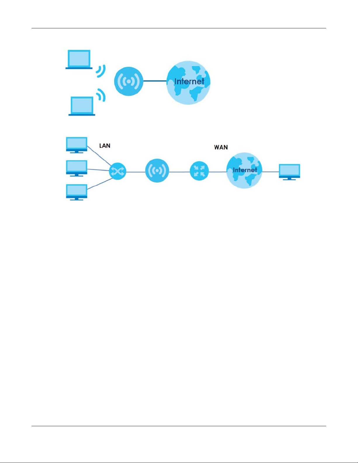
Chapter 1 Introduction
Figure 2 Internet Access Application: Wireless Connection
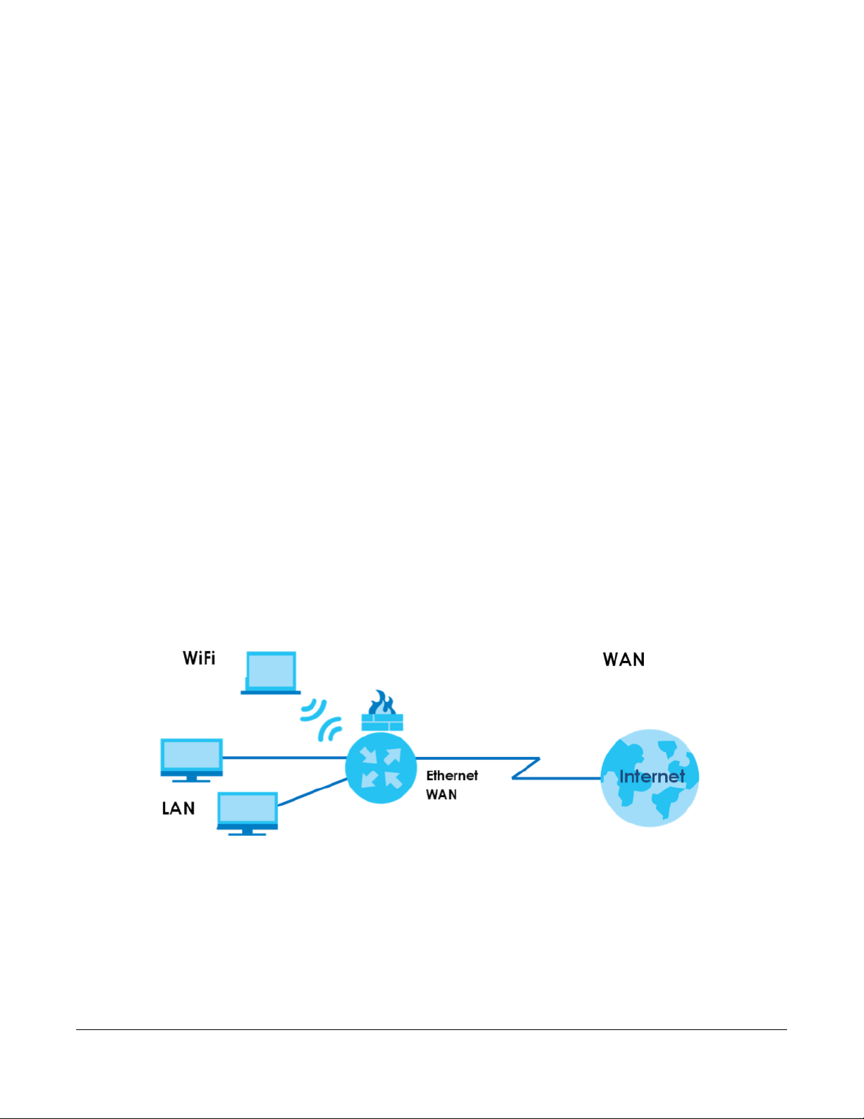
• WAN. Connect to a broadband modem/router for Internet access.
Figure 3 Internet Access Application: Ethernet WAN
1.3 Ways to Manage the NBG6818
Use the following method to manage the NBG6818.
• Web Configurator. This is recommended for everyday management of the NBG6818 using a
(supported) web browser.
• Zyxel ARMOR. This is the app you can use to manage the NBG6818 on your cellphone. To install the
app, scan the QR code on the QSG.
1.4 Good Habits for Managing the NBG6818
Do the following things regularly to make the NBG6818 more secure and to manage the NBG6818 more
effectively.
• Change the password. Use a password that’s not easy to guess and that consists of different types of
characters, such as numbers and letters.
• Write down the password and put it in a safe place.
• Back up the configuration (and make sure you know how to restore it). Restoring an earlier working
configuration may be useful if the device becomes unstable or even crashes. If you forget your
password, you will have to reset the NBG6818 to its factory default settings. If you backed up an
earlier configuration file, you would not have to totally re-configure the NBG6818. You could simply
restore your last configuration.
NBG6818 User’s Guide
12

Chapter 1 Introduction
1.5 Resetting the NBG6818
If you forget your password or IP address, or you cannot access the Web Configurator, insert a thin
object into the Reset hole on the side of the NBG6818 to reload the factory-default configuration file.
This means that you will lose all settings that you had previously saved.
1.5.1 How to Use the RESET Button
1 Make sure the power LED is on.
2 Locate the Reset hole.
3 Insert a thin object into the Reset hole for longer than eight seconds to reset the NBG6818 back to its
factory-default configuration.
1.6 The WPS Button
Your NBG6818 supports Wi-Fi Protected Setup (WPS), which is an easy way to set up a secure wireless
network. WPS is an industry standard specification, defined by the Wi-Fi Alliance.
WPS allows you to quickly set up a wireless network with strong security, without having to configure
security settings manually. Each WPS connection works between two devices. Both devices must
support WPS (check each device’s documentation to make sure).
Depending on the devices you have, you can either press a button (on the device itself, or in its
configuration utility) or enter a PIN (a unique Personal Identification Number that allows one device to
authenticate the other) in each of the two devices. When WPS is activated on a device, it has two
minutes to find another device that also has WPS activated. Then, the two devices connect and set up
a secure network by themselves.
You can use the WPS button in the Web Configurator of the NBG6818 to activate WPS in order to quickly
set up a wireless network with strong security.
1 Make sure the power LED is on (not blinking).
2 Open the Web Configurator.
3 Click Settings > WiFi > WPS, and the press the WPS button.
4 Press the WPS button on another WPS-enabled device within range of the NBG6818.
Note: You must activate WPS in the NBG6818 and in another wireless device within two
minutes of each other.
For more information on using WPS, see Section 7.2 on page 42.
NBG6818 User’s Guide
13
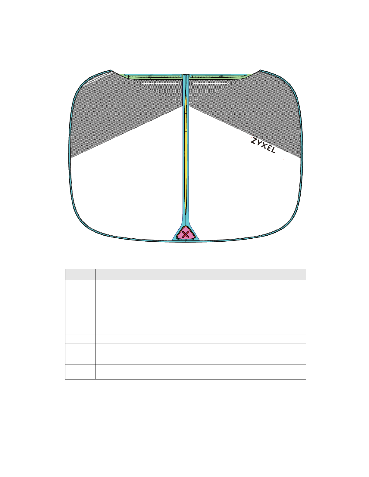
1.7 LEDs
Figure 4 Front Panel
Chapter 1 Introduction
The following table describes the front panel LED.
Table 1 Front Panel LED
COLOR STATUS DESCRIPTION
White On The NBG6818 is receiving power.
Blinking The NBG6818 is booting.
Dark Blue On Blue tooth is ready.
Blinking Blue tooth configuration is in process.
Amber Blinking (Slow) The NBG6818 is upgrading firmware.
Blinking (Fast) The NBG6818 is resetting.
Purple Blinking WPS configuration is in process.
Purple
and Dark
Blue
Red On The NBG6818 detects and error while self-testing, or there is a
Blinking The NBG6818 is receiving power and ready for use.
device malfunction.
NBG6818 User’s Guide
14
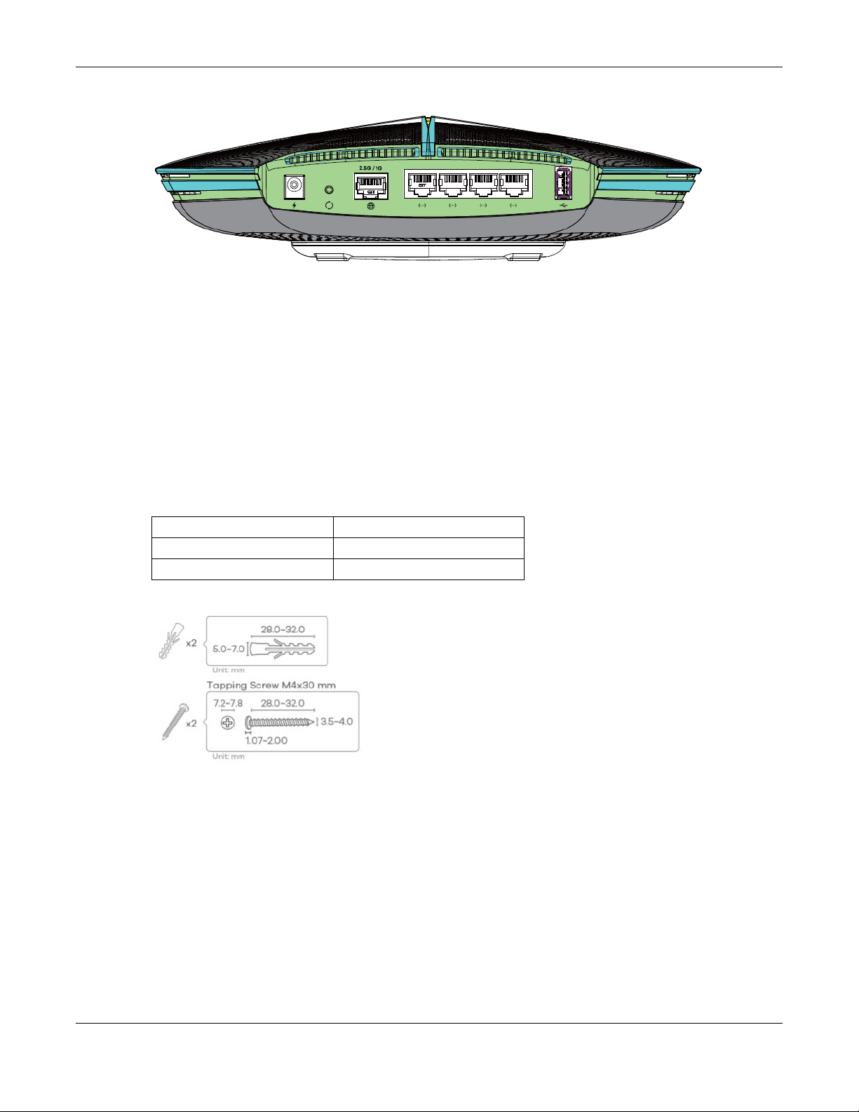
Figure 5 Rear Panel
1.8 Desk Mounting
Place the side of the NBG6818 with rubber feet carefully on the desk.
1.9 Wall Mounting
Chapter 1 Introduction
You may need screw anchors if mounting on a concrete or brick wall.
Table 2 Wall Mounting Information
Distance between holes 10.50 cm
M4 Screws Two
Screw anchors (optional) Two
Figure 6 Screw Specifications
1 Select a position free of obstructions on a wall strong enough to hold the weight of the device.
2 Mark two holes on the wall at the appropriate distance apart for the screws.
Be careful to avoid damaging pipes or cables located inside the wall when
drilling holes for the screws.
3 If using screw anchors, drill two holes for the screw anchors into the wall. Push the anchors into the full
depth of the holes, then insert the screws into the anchors. Do not insert the screws all the way in - leave
a small gap of about 0.5 cm.
If not using screw anchors, use a screwdriver to insert the screws into the wall. Do not insert the screws all
the way in - leave a gap of about 0.5 cm.
NBG6818 User’s Guide
15
Chapter 1 Introduction
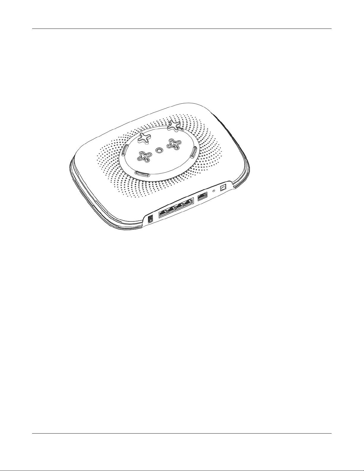
4 Make sure the screws are fastened well enough to hold the weight of the NBG6818 with the connection
cables.
5 Remove the rubber feet.
6 Align the holes on the back of the NBG6818 with the screws on the wall. Hang the NBG6818 on the
screws.
Figure 7 Wall Mounting- Rubber Feet
NBG6818 User’s Guide
16
2.1 Overview
In this chapter, you will learn how to:
• Go through NBG6818 (ARMOR G1) wizard steps
• Configure basic settings for your WiFi
• Create a myZyxel Cloud account.
2.2 Accessing the Wizard
Launch your web browser and type "http://zyxelwifi.com" or "http://zyxelwifi.net" as the website
address.
CHAPTER 2
Wizard
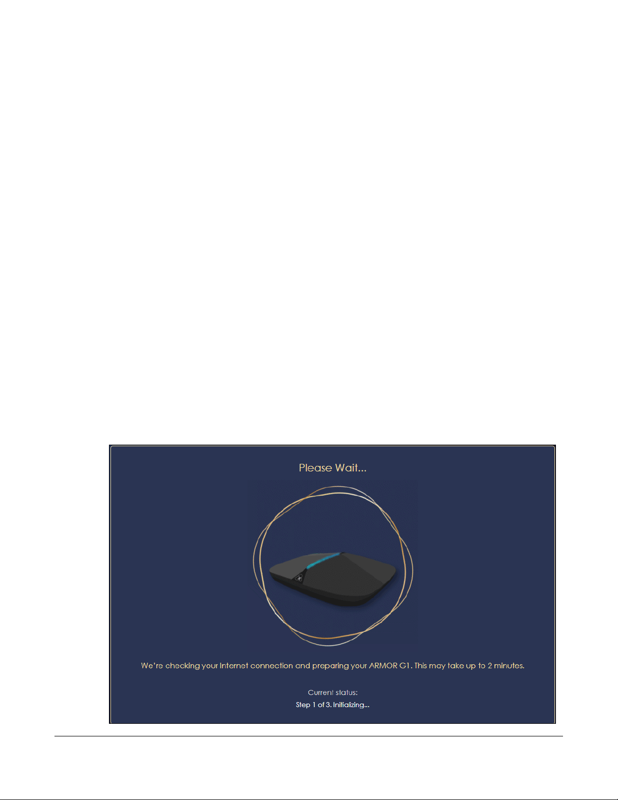
Note: The wizard appears automatically when the NBG6818 is accessed for the first time or
when you reset the NBG6818 to its default factory settings.
1 Your NBG6818 will check the status of your Internet connection the first time you log in.
NBG6818 User’s Guide
17
Chapter 2 Wizard
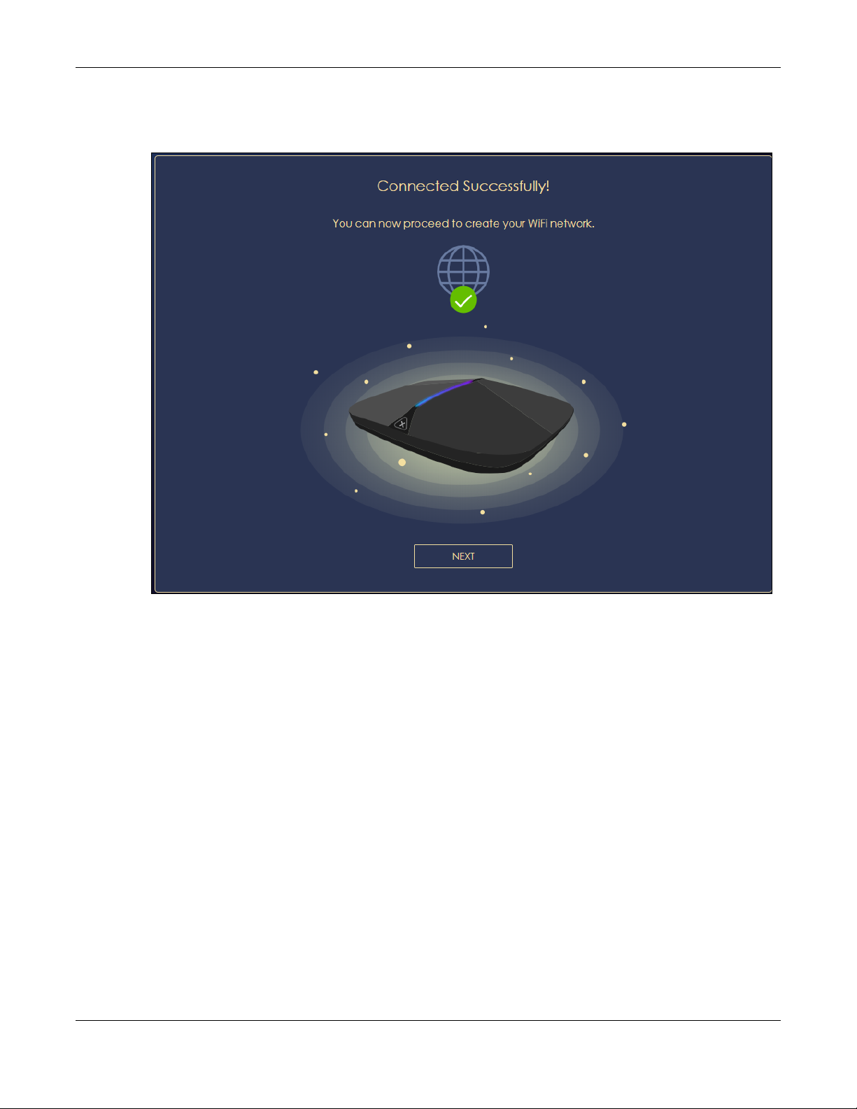
2 The following screen shows if you are connected to the Internet. Click Next to go to the next step in the
wizard.
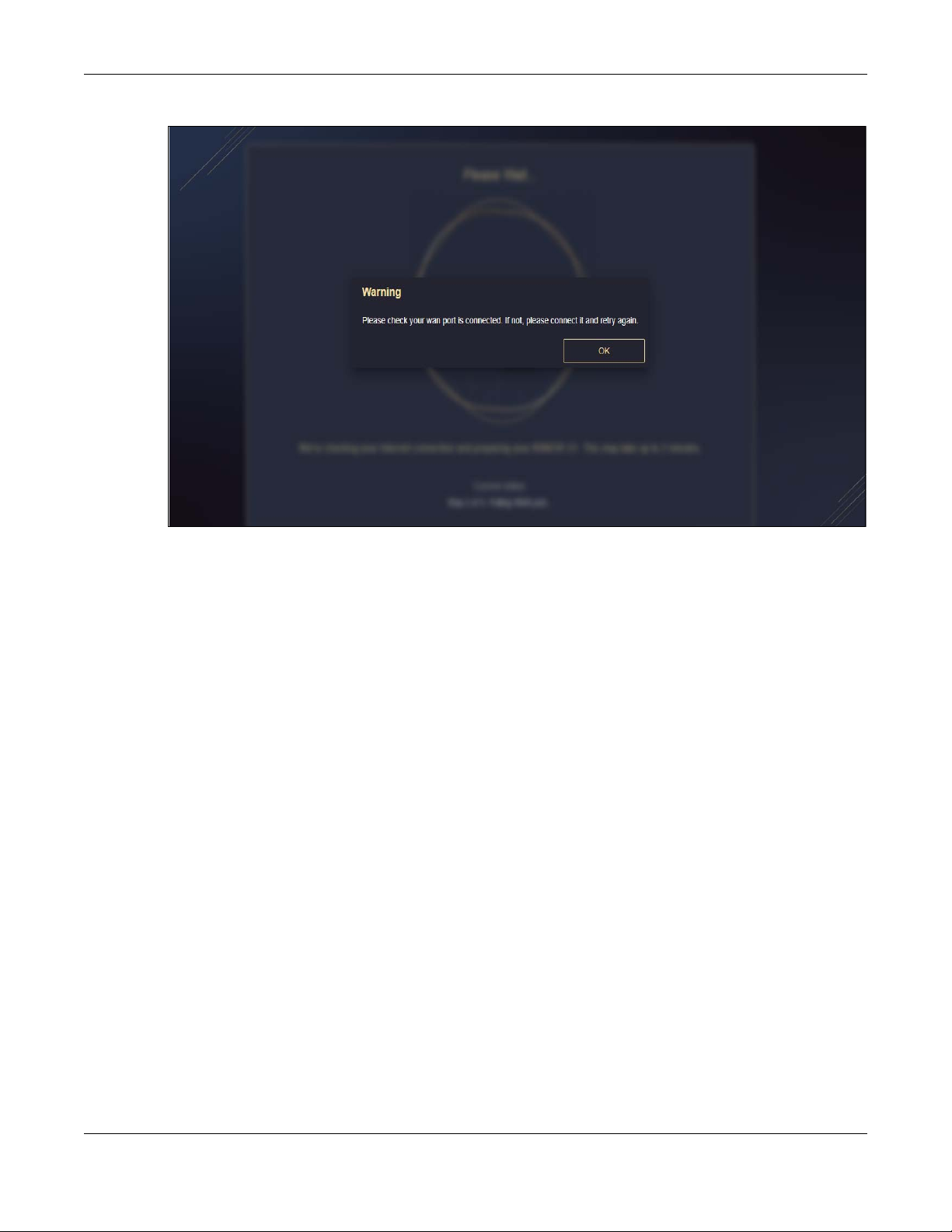
The following screen shows if you are not connected to the Internet.
Note: You may need to turn off your network firewall if access to the Internet from the
NBG6818 is blocked.
You need to connect to the Internet to access your NBG6818. See Section 14.4 on
page 143 if you cannot connect to the Internet.
NBG6818 User’s Guide
18
Chapter 2 Wizard
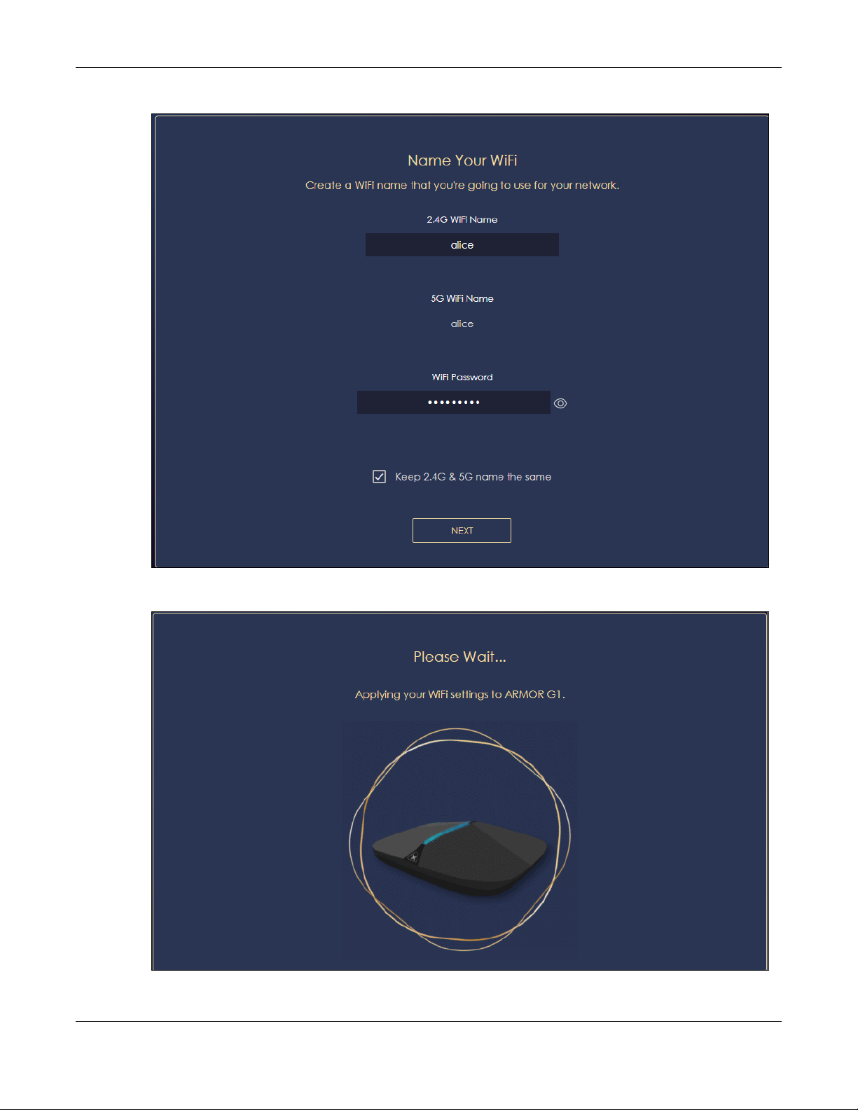
3 Enter 1-128 single-byte printable ASCII characters but not "''<>^$& as your 2.4G/5G WiFi Name and WiFi
Password. Select the check box Keep 2.4G & 5G name the same if you want to use the same name for
your 2.4G and 5G WiFi.
NBG6818 User’s Guide
19
Chapter 2 Wizard
4 Wait a moment for your WiFi settings to be applied to your NBG6818.
NBG6818 User’s Guide
20
Chapter 2 Wizard
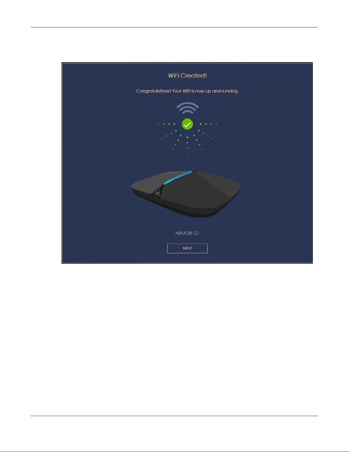
5 The following screen shows if you have set up your WiFi name and password successfully. Click Next to
go to the next step in the wizard.
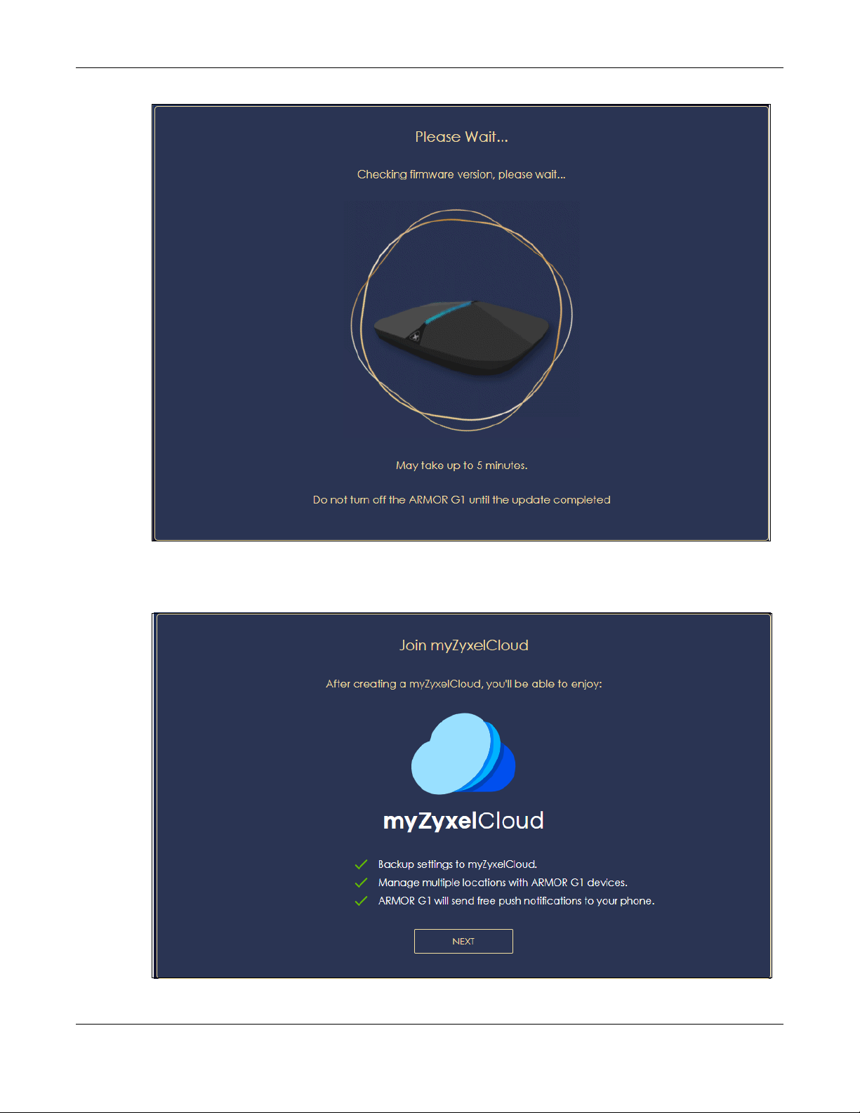
6 Wait a moment for the NBG6818 to check if your device is updated with the latest firmware. If not, your
NBG6818 will automatically update the firmware.
NBG6818 User’s Guide
21
Chapter 2 Wizard
7 You need to create a myZyxel Cloud account to log into the NBG6818. Click Next to go to the next step
in the wizard.
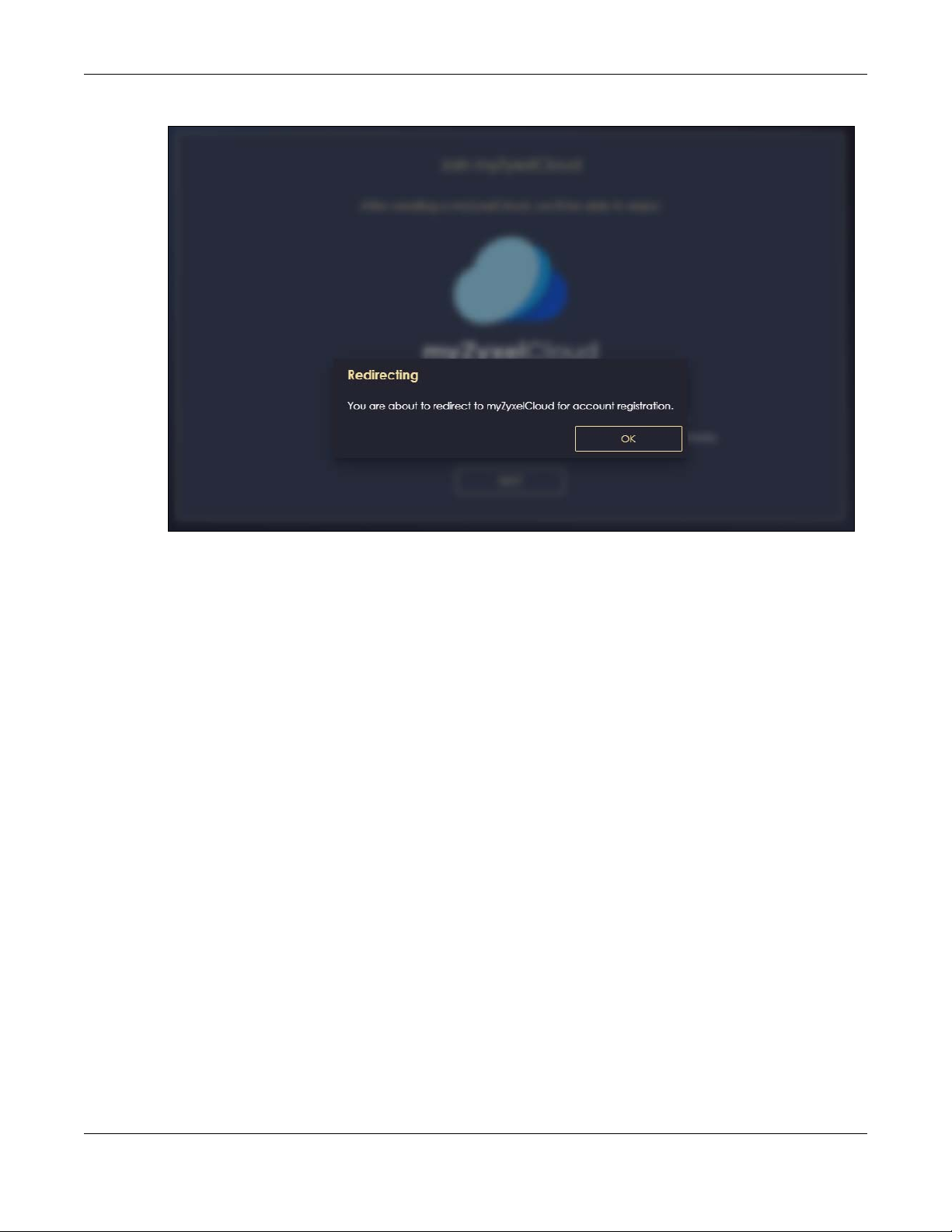
8 A pop up message shows. Click OK to be redirected to the registration website of myZyxel Cloud.
NBG6818 User’s Guide
22
Chapter 2 Wizard
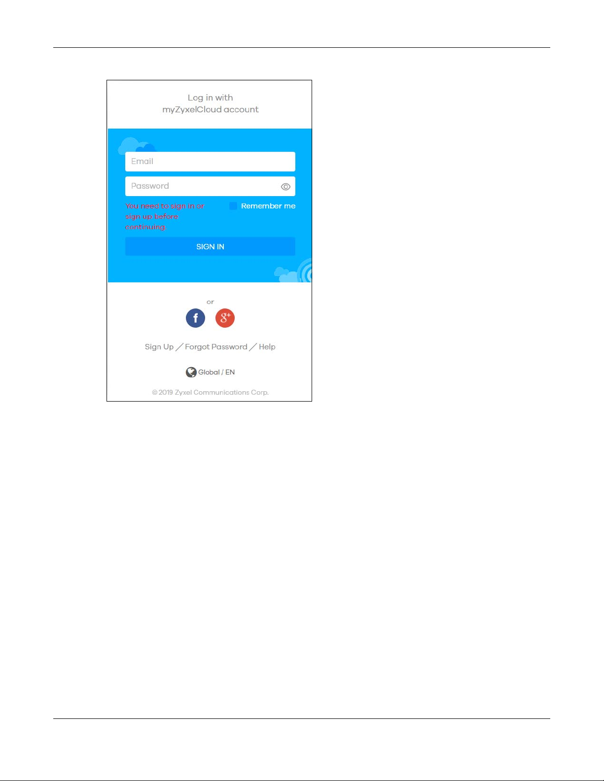
9 Enter your Email and Password if you already have a myZyxel Cloud account. If not, you can create one
by clicking Sign Up. You can also click the Facbook or Google icon to create an account with your
Facebook or Google account.
NBG6818 User’s Guide
23
Chapter 2 Wizard
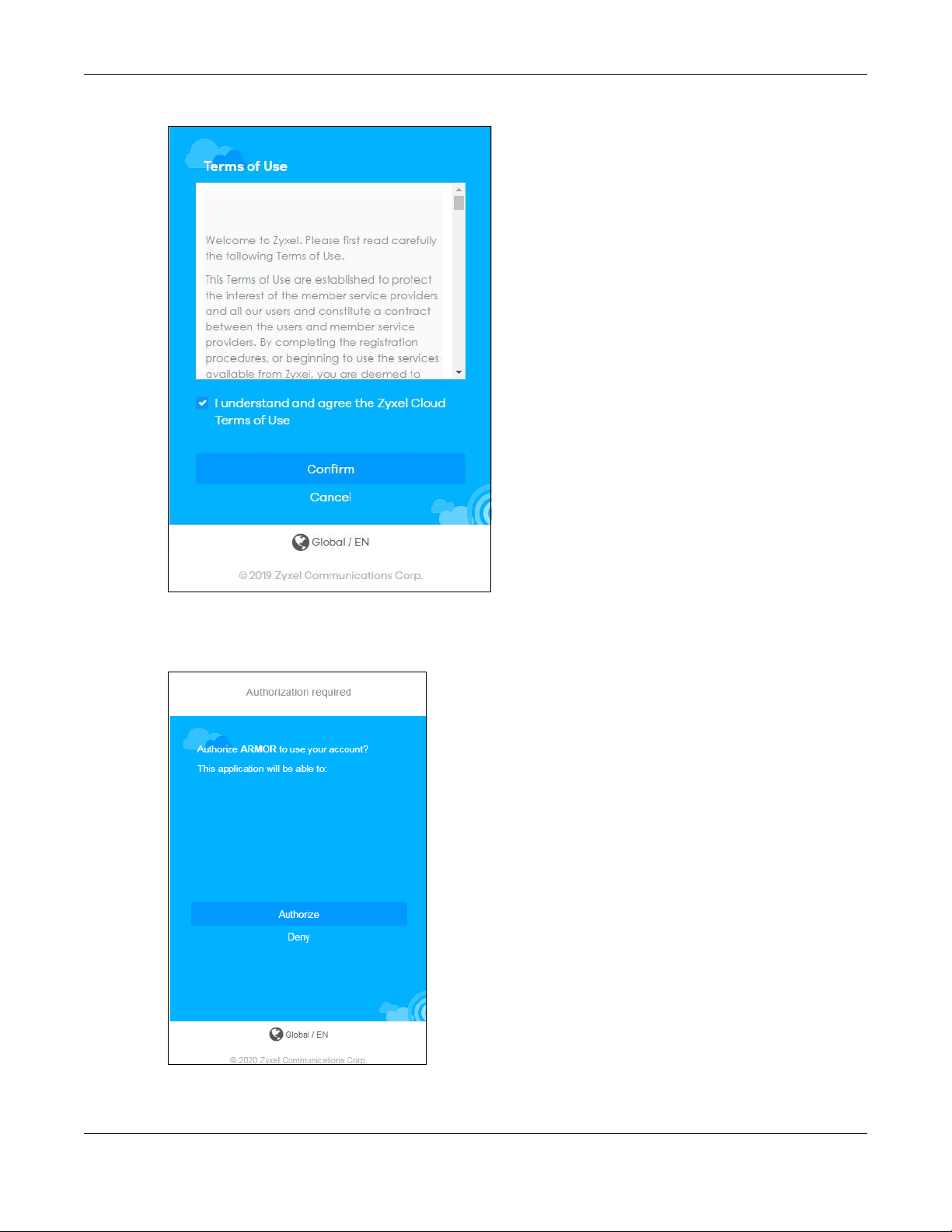
10 The legal page shows after you log in. Select the check box I understand and agree the Zyxel Cloud
Terms of Use and then click Confirm.
NBG6818 User’s Guide
24
Chapter 2 Wizard
11 The following page asks for your authorization to use your account. Click Authorize to finish registering
your myZyxel Cloud account. You will be directed back to the NBG6818 web configurator.
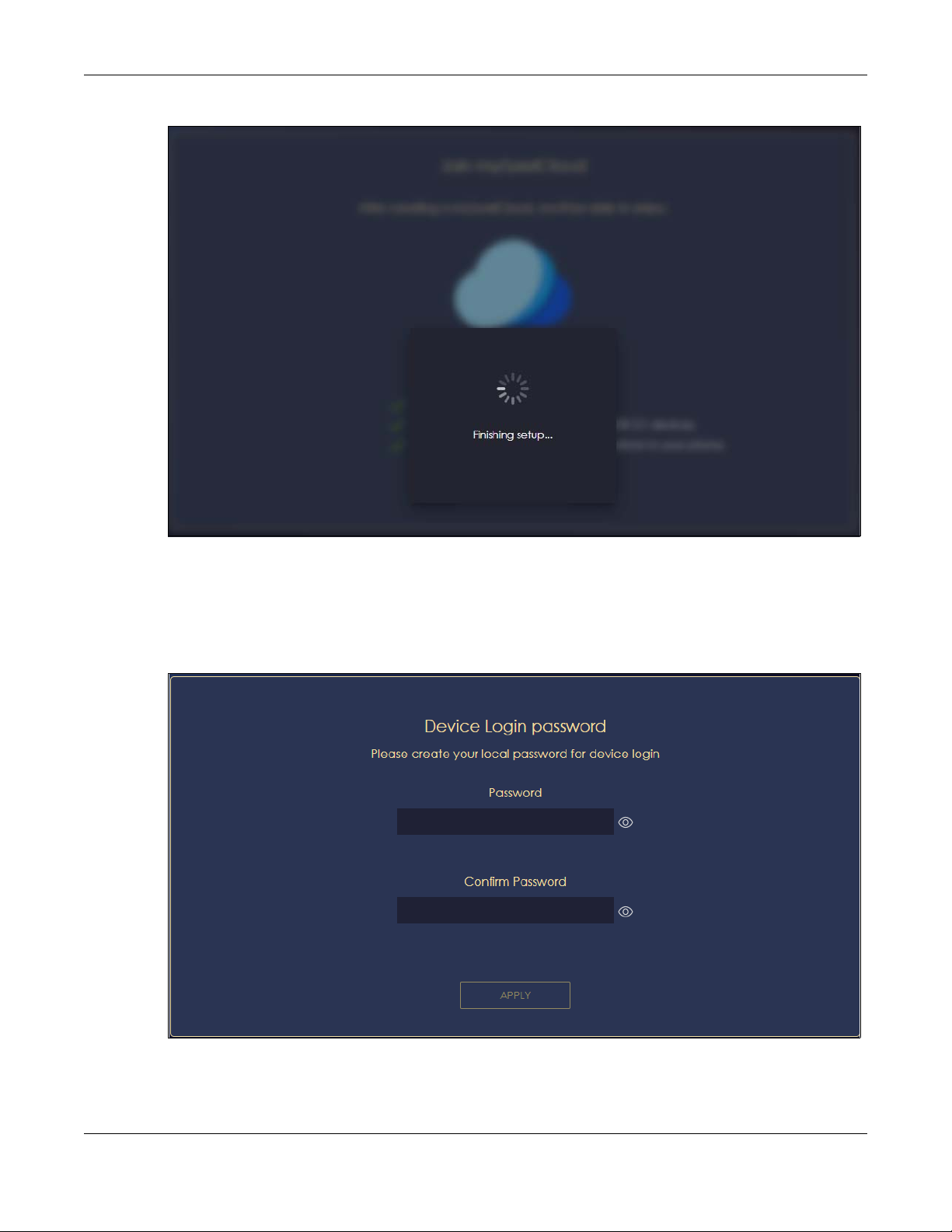
12 Wait a moment for your NBG6818 to link to your myZyxel Cloud account.
NBG6818 User’s Guide
25
Chapter 2 Wizard
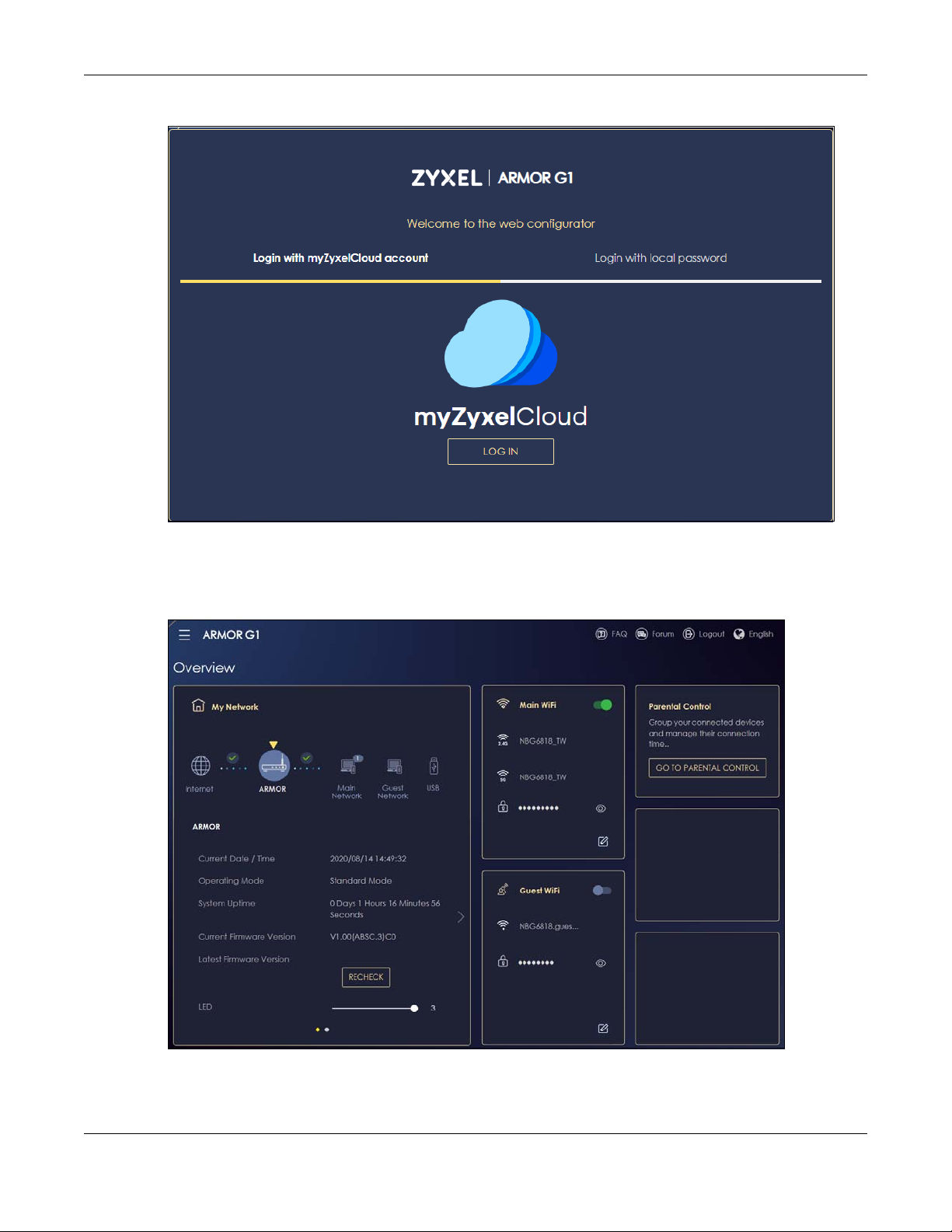
13 You can create a local password to access the NBG6818 directly. You can choose to log in with your
myZyxel Cloud account or your local password the next time you log in.
Note: You can change your local password in System > General Settings. See Section 13.4 on
page 133 for more information.
NBG6818 User’s Guide
26

3.1 Overview
This chapter describes how to access the NBG6818 Web Configurator and provides an overview of its
screens.
The Web Configurator is an HTML-based management interface that allows easy system setup and
management via Internet browser. Use a browser that supports HTML5, such Mozilla Firefox, or Google
Chrome. The recommended screen resolution is 1024 by 768 pixels.
In order to use the Web Configurator you need to allow:
• Web browser pop-up windows from your device.
• JavaScript (enabled by default).
• Java permissions (enabled by default).
CHAPTER 3
The Web Configurator
3.2 Accessing the Web Configurator
1 Make sure your NBG6818 hardware is properly connected (refer to the Quick Start Guide).
2 Launch your web browser.
3 If the NBG6818 is in Standard Mode (the default mode), enter "http://zyxelwifi.com" in the browser’s
address bar.
If the NBG6818 is in Bridge Mode, type “http:// (DHCP-assigned IP)” in the browser’s address bar.
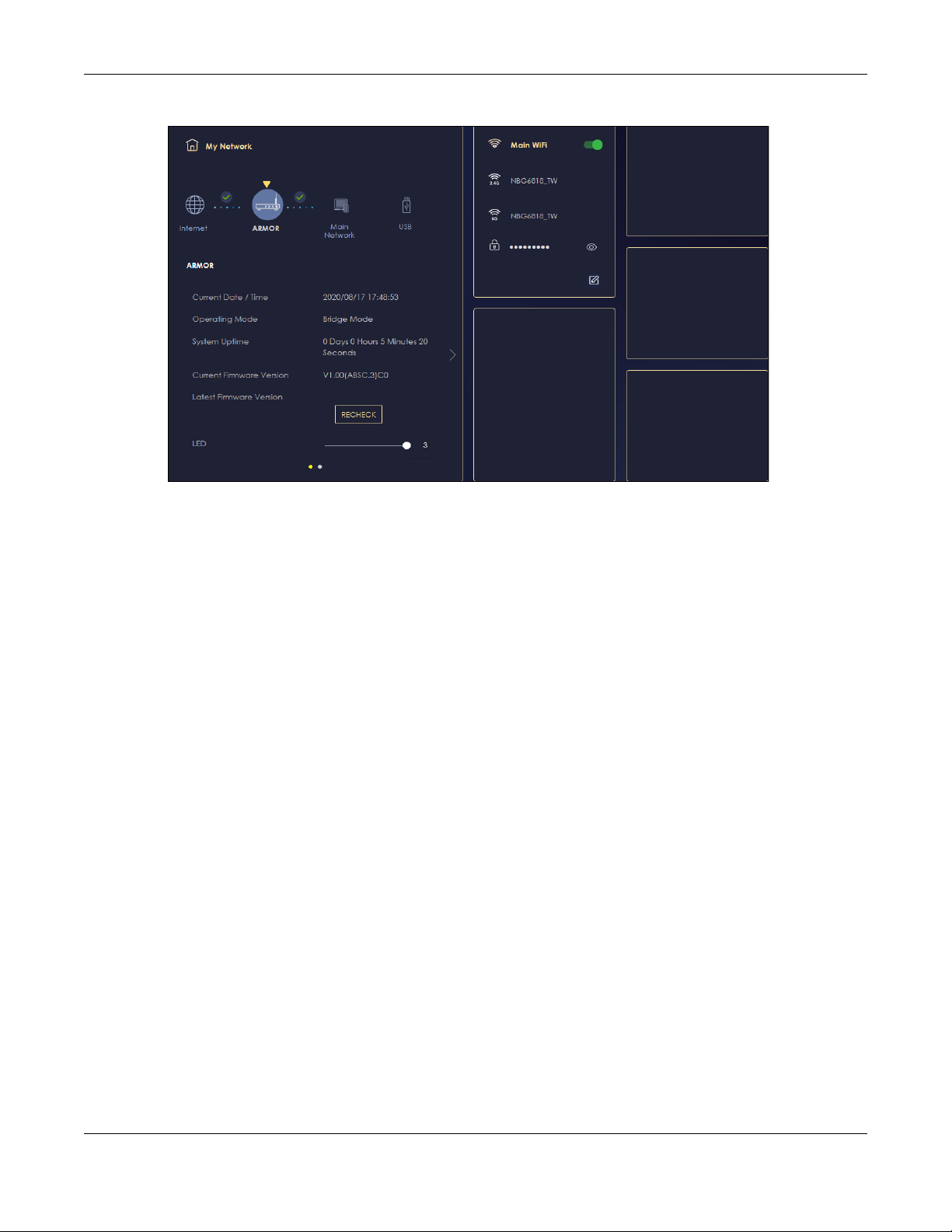
4 On the displayed login screen, log in using your myZyxelCloud username and password or the local
password.
Note: If this is the first time you are accessing the web configurator or if the device has been
reset, you must complete the setup wizard, see Chapter 2 on page 17.
Note: For setting and changing the local password, see Section 13.4 on page 133.
NBG6818 User’s Guide
27
Chapter 3 The Web Configurator
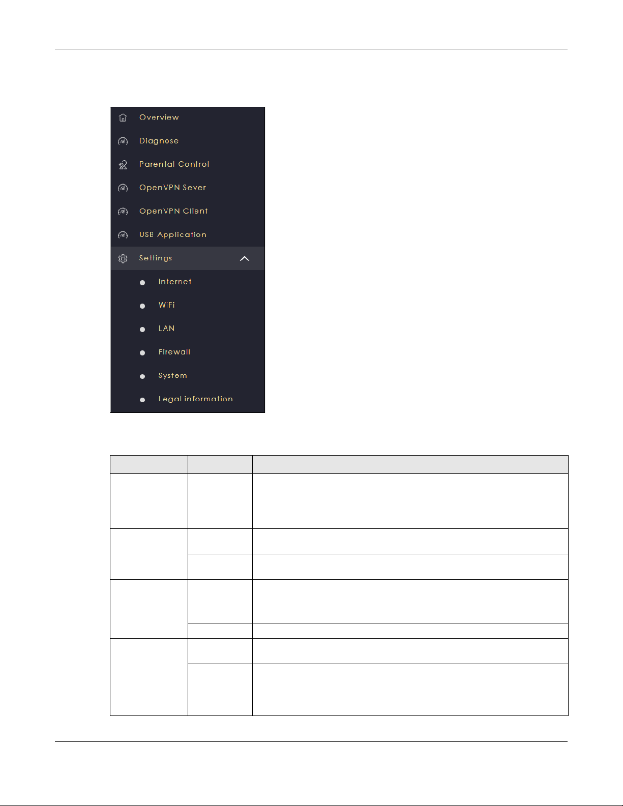
5 The NBG6818 Overview screen displays allowing you to monitor your NBG6818. It shows if the NBG6818 is
online, and how many wireless clients are currently connected to your device, as well as their upstream/
downstream data rates.
Figure 8 Overview (Standard Mode)
NBG6818 User’s Guide
28
Chapter 3 The Web Configurator
Figure 9 Overview (Bridge Mode)
3.3 Navigation Panel
Use the submenus on the navigation panel to configure NBG6818 features. Your navigation panel varies
depending on the mode of your NBG6818.
See Chapter 5 on page 36 for more information on Standard Mode.
See Chapter 6 on page 39 for more information on Bridge Mode.
NBG6818 User’s Guide
29
Chapter 3 The Web Configurator
3.3.1 Standard Mode Navigation Panel
Figure 10 Navigation Panel (Standard Mode)
The following table describes the submenus.
Table 3 Settings > System > Status (Standard Mode)
LINK TAB FUNCTION
Overview Use this screen to:
• View read-only information about your NBG6818
• Configure WiFi settings
• Change the brightness of your device’s LED
Diagnose Advanced
Speed Test
Speed Test
History
Parental Control Device Use this screen to:
Profile Use this screen to enable or configure existing parental control rules.
OpenVPN Server OpenVPN
Server
OpenVPN
Account
Use this screen to check the speed of the connection between your NBG6818
and the broadband modem/router.
Use this screen to view a summary of previously run speed tests.
• View devices information
• Add and configure parental control rules or schedules
Use this screen to create and configure an OpenVPN server account.
Use this screen to:
• View basic information about NBG6818 OpenVPN server
• View basic information about clients that are connected to the NBG6818
OpenVPN server
NBG6818 User’s Guide
30

Chapter 3 The Web Configurator
Table 3 Settings > System > Status (Standard Mode) (continued)
LINK TAB FUNCTION
OpenVPN Client Use this screen to:
• View basic information about OpenVPN Server accounts that you are
connected to
• Add an OpenVPN Server Account you want your NBG6818 to connect to
when the NBG6818 functions as an OpenVPN client.
USB Application SAMBA Use this screen to:
• Set up file-sharing via the NBG6818 using Windows Explorer or the
workgroup name
• Configure the workgroup name and create file-sharing user accounts
FTP Use this screen to set up file sharing via the NBG6818 using FTP and create user
accounts.
USB Media
Sharing
Internet Internet
Connection
NAT & Port
Forwarding
Passthrough Use this screen to change your NBG6818’s port triggering settings.
Port Trigger Use this screen to configure ALGs (Application Layer Gateway) and VPN pass-
Dynamic DNS Use this screen to configure dynamic DNS.
UPnP Use this screen to enable UPnP on the NBG6818.
WiFi Main WiFi Use this screen to enable the wireless LAN and configure wireless LAN and
Guest WiFi Use this screen to configure multiple BSSs on the NBG6818.
MAC Filter Use the MAC filter screen to configure the NBG6818 to block access to devices
WPS Use this screen to configure WPS.
Scheduling Use this screen to schedule the times the Wireless LAN is enabled.
LAN LAN IP Use this screen to configure the NBG6818’s LAN IP address and subnet mask.
IPv6 LAN Use this screen to configure the IPv6 address for your NBG6818 on the LAN.
Firewall IPv4 Firewall Use this screen to configure IPv4 firewall rules.
IPv6 Firewall Use this screen to configure IPv6 firewall rules.
Use this screen to configure settings for media sharing.
This screen allows you to configure ISP parameters, WAN IP address
assignment, DNS servers and the WAN MAC address.
Use this screen to enable NAT.
Use this screen to configure servers behind the NBG6818 and forward incoming
service requests to the servers on your local network.
through settings.
wireless security settings.
or block the devices from accessing the NBG6818.
Use this screen to configure the IPv6 address for the NBG6818 on the LAN.
Use this screen to enable the NBG6818’s DHCP server.
NBG6818 User’s Guide
31

Chapter 3 The Web Configurator
Table 3 Settings > System > Status (Standard Mode) (continued)
LINK TAB FUNCTION
System Status Use this screen to view the basic information of the NBG6818
General
Setting
Remote
Access
Maintenance Use this screen to upload firmware, reboot the NBG6818 without turning the
Operating
Mode
Logs Use this screen to view the list of activities recorded by your NBG6818.
Use this screen to change password or to set the timeout period of the
management session.
Use this screen to configure the interface/s from which the NBG6818 can be
managed remotely and specify a secure client that can manage the
NBG6818.
power off or reset the NBG6818 to factory default.
Use this screen to select whether your device acts as a router, or a bridge.
3.3.2 Bridge Mode Navigation Panel
Figure 11 Navigation Panel (Bridge Mode)
The following table describes the submenus.
Table 4 Settings > System > Status (Bridge Mode)
LINK TAB FUNCTION
Overview Use this screen to:
• View read-only information about your NBG6818
• Configure WiFi settings
• Change the brightness of your device’s LED
Diagnose Advanced
Speed Test
Speed Test
History
Use this screen to check the speed of the connection between your NBG6818
and the broadband modem/router.
Use this screen to view a summary of previously run speed tests.
NBG6818 User’s Guide
32

Chapter 3 The Web Configurator
Table 4 Settings > System > Status (Bridge Mode) (continued)
LINK TAB FUNCTION
USB Application SAMBA Use this screen
• Set up file-sharing via the NBG6818 using Windows Explorer or the
workgroup name
• Configure the workgroup name and create file-sharing user accounts
FTP Use this screen to set up file sharing via the NBG6818 using FTP and create user
accounts.
USB Media
Sharing
WiFi Main WiFi Use this screen to enable the wireless LAN and configure wireless LAN and
MAC Filter Use the MAC filter screen to configure the NBG6818 to block access to devices
WPS Use this screen to configure WPS.
Scheduling Use this screen to schedule the times the Wireless LAN is enabled.
LAN LAN IP Use this screen to configure the NBG6818’s LAN IP address and subnet mask.
System Status Use this screen to view the basic information of the NBG6818
General
Setting
Remote
Access
Maintenance Use this screen to upload firmware, reboot the NBG6818 without turning the
Operating
Mode
Logs Use this screen to view the list of activities recorded by your NBG6818.
Use this screen to configure settings for media sharing.
wireless security settings.
or block the devices from accessing the NBG6818.
Use this screen to configure the IPv6 address for the NBG6818 on the LAN.
Use this screen to enable the NBG6818’s DHCP server.
Use this screen to change password or to set the timeout period of the
management session.
Use this screen to enable remote assistant.
power off or reset the NBG6818 to factory default.
Use this screen to select whether your device acts as a router, or a bridge.
NBG6818 User’s Guide
33

4.1 Overview
This chapter introduces the different operating modes available on your NBG6818. Or simply how the
NBG6818 is being used in the network.
4.2 Modes
This refers to the operating mode of the NBG6818, which can act in:
Chapter 4 NBG6818 Modes
CHAPTER 4
NBG6818 Modes
• Standard Mode: This is the default device mode of the NBG6818. Use this mode to connect the local
network to another network, like the Internet. Go to Section 5.3 on page 36 to view the Status screen
in this mode.
Figure 12 Standard Mode Example
• Bridge Mode: Use this mode if you want to extend your network by allowing network devices to
connect to the NBG6818 wirelessly. Go to Section 6.4 on page 41 to view the Status screen in this
mode.
NBG6818 User’s Guide
34

Chapter 4 NBG6818 Modes
Figure 13 Bridge Mode Example
For more information on changing the mode of your NBG6818, refer to Section 13.7 on page 137.
Note: Choose your device mode carefully to avoid having to change it later.
When changing to another mode, the IP address of the NBG6818 changes. The running applications
and services of the network devices connected to the NBG6818 may be interrupted.
NBG6818 User’s Guide
35

5.1 Overview
The NBG6818 is set to standard (router) mode by default. Routers are used to connect the local network
to another network (for example, the Internet). In the figure below, the NBG6818 connects the local
network (LAN1 ~ LAN4) to the Internet.
Figure 14 NBG6818 in Standard Mode
Chapter 5 Standard Mode
CHAPTER 5
Standard Mode
5.2 What You Can Do
• Use the Status screen to view read-only information about your NBG6818 (Section 5.3 on page 36).
5.3 Standard Mode Status Screen
Click Settings > System > Status to open the status screen.
NBG6818 User’s Guide
36

Chapter 5 Standard Mode
Figure 15 Settings > System > Status (Standard Mode)
The following table describes the labels shown in the Status screen.
Table 5 Settings > System > Status (Standard Mode)
LABEL DESCRIPTION
System
Model Name This is the model name of your device.
Firmware Version This is the firmware version.
System Operation Mode This is the device mode to which the NBG6818 is set, see Section 13.7 on page 137 for
Enable IPv4 Firewall This shows if the IPv4 firewall is enabled on the NBG6818.
Enable IPv6 Simple
Security
System Uptime This is the total time the NBG6818 has been on.
WAN Information
MAC Address This shows the WAN Ethernet adapter MAC Address of your device.
IP Address This shows the WAN port’s IP address.
more information.
This shows if the IPv6 firewall is enabled on the NB6818.
NBG6818 User’s Guide
37

Chapter 5
Table 5 Settings > System > Status (Standard Mode) (continued)
LABEL DESCRIPTION
IP Subnet Mask This shows the WAN port’s subnet mask.
Gateway This shows the WAN port’s gateway IP address.
IPv6 Address This shows the current IPv6 address of the NBG6818.
LAN Information
MAC Address This shows the LAN Ethernet adapter MAC Address of your device.
IP Address This shows the LAN port’s IP address.
IP Subnet Mask This shows the LAN port’s subnet mask.
DHCP Server This shows the LAN port’s DHCP role - Enable or Disable.
IPv6 Address This shows the current IPv6 address of the NBG6818 in the LAN.
NBG6818 User’s Guide
38

6.1 Overview
Use your NBG6818 as a bridge if you already have a router or gateway on your network. In this mode
your NBG6818 bridges a wired network (LAN) and wireless LAN (WLAN) in the same subnet. See the
figure below for an example.
Figure 16 NBG6818 in Bridge Mode
Chapter 6 Bridge Mode
CHAPTER 6
Bridge Mode
Many screens that are available in Standard Mode are not available in Bridge Mode, such as port
forwarding and firewall. See Section 3.3 on page 29 for more information.
6.2 What You Can Do
• Set up a network with the NBG6818 as a bridge (Section 6.3 on page 39).
• Use the Status screen to view read-only information about your NBG6818 (Section 6.4 on page 41).
6.3 Setting your NBG6818 to Bridge Mode
1 Log into the Web Configurator if you haven’t already. See the Quick start Guide for instructions on how
to do this.
NBG6818 User’s Guide
39

Chapter 6 Bridge Mode
2 To use your NBG6818 as a bridge, go to Settings > System > Operating Mode and select Bridge Mode.
Figure 17 Changing to Bridge mode
Note: You have to log in to the Web Configurator again when you change modes. As soon as
you do, your NBG6818 is already in Bridge mode.
3 When you select Bridge Mode, the following pop-up message window appears.
Figure 18 Pop up for Bridge mode
Click OK. Then click Apply. The Web Configurator refreshes once the change to Bridge mode is
successful.
6.3.1 Accessing the Web Configurator in Bridge Mode
Log in to the Web Configurator in Bridge mode, do the following:
1 Connect your computer to the LAN port of the NBG6818.
2 The default IP address of the NBG6818 in bridge mode is “192.168.123.2”. In this case, your computer
must have an IP address in the range between “192.168.123.3” and “192.168.123.254”.
3 Click Start > Run on your computer in Windows. Type “cmd” in the dialog box. Enter “ipconfig” to show
your computer’s IP address. If your computer’s IP address is not in the correct range then see Appendix
B on page 153 for information on changing your computer’s IP address.
4 After you’ve set your computer’s IP address, open a web browser such as Internet Explorer and type
“192.168.123.2” as the web address in your web browser.
NBG6818 User’s Guide
40

Chapter 6 Bridge Mode
6.4 Bridge Mode Status Screen
Click Settings > System > Status to open the status screen.
Figure 19 Settings > System > Status (Bridge Mode)
The following table describes the labels shown in the Status screen.
Table 6 Settings > System > Status (Bridge Mode)
LABEL DESCRIPTION
System
Model Name This is the model name of your device.
Firmware Version This is the firmware version.
System Operation Mode This is the device mode to which the NBG6818 is set, see Section 13.7 on page 137
for more information.
Enable IPv4 Firewall This shows if the IPv4 firewall is enabled on the NBG6818.
Enable IPv6 Simple Security This shows if the IPv6 firewall is enabled on the NB6818.
System Uptime This is the total time the NBG6818 has been on.
LAN Information
MAC Address This shows the LAN Ethernet adapter MAC Address of your device.
IP Address This shows the LAN port’s IP address.
IP Subnet Mask This shows the LAN port’s subnet mask.
DHCP Server This shows the LAN port’s DHCP role - Enable or Disable.
IPv6 Address This shows the current IPv6 address of the NBG6818 in the LAN.
NBG6818 User’s Guide
41

7.1 Overview
This chapter provides tutorials for setting up your NBG6818.
• Run a Speed Test
• Configure the NBG6818’s WiFi Networks
• Enable or Disable a WiFi Network
• Add Clients to a Profile
• Set a Profile’s WiFi Schedule
• Pause or Resume Internet Access on a Profile
• Change Your NBG6818 Operating Mode
• Configure a Port Forwarding Rule
CHAPTER 7
Tutorials
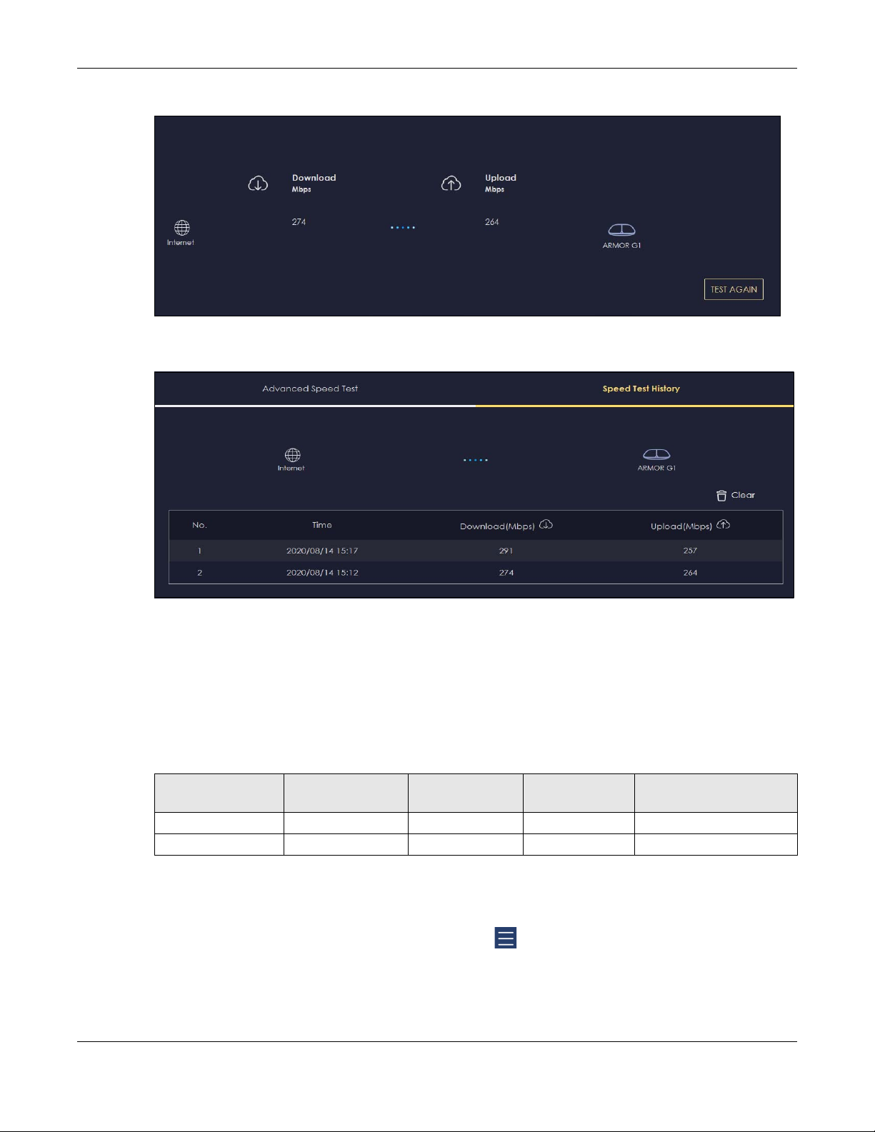
7.2 Run a Speed Test
With the NBG6818 Web Configurator, you can check the speed of the connection between your
NBG6818 and the broadband modem/router.
1 Click the Navigation Panel icon on the top-left corner ( ), and click Diagnose to open the Advanced
Speed Test screen. Use this screen to view all the available connections in your NBG6818 System.
2 Click TEST to perform a speed test. This shows data rates for both upstream and downstream traffic. Click
TEST AGAIN to update the information in this screen.
NBG6818 User’s Guide
42
Chapter 7 Tutorials
3 Click the Speed Test History tab to view a summary of the tests made. Click Clear to delete all records.
7.3 Configure the NBG6818’s WiFi Networks
In the NBG6818 you can configure independent wireless networks with different privileges. Clients can
associate only with the network for which they have security settings (SSID and password). The following
table describes the different NBG6818’s profile networks and their privileges.
Table 7 WiFi Network Privileges
WIFI NETWORK INTERNET ACCESS
Main WiFi Yes 2.4G and 5G Yes Yes
Guest WiFi Yes 2.4G and 5G No No
2.4G / 5G WIFI
NETWORK
Note: A user can only configure the WiFi networks’ security settings if they are connected to
the Main WiFi network.
1 Click the Navigation Panel icon on the top-left corner ( ), and click Settings to open the WiFi screen.
Use each tab in the WiFi menu to configure each of the WiFi networks’ security settings.
NBG6818 User’s Guide
ACCESS TO WEB
CONFIGURATOR
ACCESS TO WIRED LAN
43

Chapter 7 Tutorials
2 Select Enable to activate a WiFi Network. Enter the 2.4G/5G Name and Password clients use to connect
to the WiFi network. You can configure two different WiFi Names for the Main WiFi 2.4G and 5G networks.
Select Keep 2.4G & 5G name the same, so they both use the same WiFi Name. Click Apply to save your
changes.
NBG6818 User’s Guide
44

Chapter 7 Tutorials
7.4 Enable or Disable a WiFi Network
After the NBG6818 is set up, you can use separate WiFi networks for your clients. The WiFi settings will be
applied to all clients in the same network.
Note: This is not available if you are using bridge mode.
1 Click the Navigation Panel icon on the top-left corner ( ), and click Settings to open the WiFi screen.
NBG6818 User’s Guide
45

Chapter 7 Tutorials
2 Enable guest WiFi and enter the WiFi Name (SSID) and WiFi Password. Click Apply to save your changes.
7.5 Add Clients to a Profile
Profiling clients allows you to easily block/allow Internet access or set a schedule for all client devices in
the same profile.
NBG6818 User’s Guide
46

Chapter 7 Tutorials
1 Click the Navigation Panel icon on the top-left corner ( ), and click Parental Control to open the
Device screen. Use the Device screen to view all the clients in your NBG6818.
2 Click the icon under Action ( ) to view the user information. In Device Detail, select a predefined profile
and click Apply.
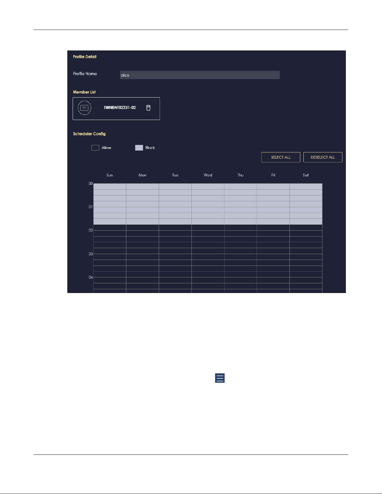
7.6 Set a Profile’s WiFi Schedule
When you create or edit a profile, you can schedule the NBG6818 to automatically disable or enable
WiFi access during a certain period of time for clients in that profile.
Note: This is not available if you are using bridge mode.
1 Click the Navigation Panel icon on the top-left corner ( ).Select Parental Control, and click the Profile
tab. Use the Profile screen to display the profiles created in the NBG6818.
NBG6818 User’s Guide
47

Chapter 7 Tutorials
2 Click Enable to activate this profile’s Internet schedule. Click the Edit icon ( ) to modify a profile’s
Internet schedule.
3 Click the start time cell and drag down to the end time to set up your schedule.
NBG6818 User’s Guide
48
Chapter 7 Tutorials
7.7 Pause or Resume Internet Access on a Profile
You may want to manually block a profile of client devices from accessing the Internet immediately
and resume it later.
Note: This is not available if you are using bridge mode.
1 Click the Navigation Panel icon on the top-left corner ( ).Select Parental Control, and click the Profile
tab. Use the Profile screen to display the profiles created in the NBG6818.
NBG6818 User’s Guide
49

Chapter 7 Tutorials
2 Click a profile’s Resume button to resume network access at once, or click the Quick Block button to
pause Internet access for that specific profile.
7.8 Turn on or off the NBG6818’s LED (Light)
1 In the Overview screen, find the LED field and drag the button of the slider to the left.
NBG6818 User’s Guide
50

Chapter 7 Tutorials
7.9 Change Your NBG6818 Operating Mode
The operating mode refers to how the NBG6818 is being used in the network. The NBG6818 has two
operating modes:
• Standard: This is the NBG6818’s default mode. In this mode, the NBG6818 routes traffic between a
local network and another network such as the Internet.
• Bridge: Use this mode so the NBG6818 bridges traffic between clients on the same network.
Note: Features such as parental Control, UPnP, Port Forwarding are not available in Bridge
mode.
1 Click the Navigation Panel icon on the top-left corner ( ).From the Settings drop-down list, click
System, then click the Operating Mode tab. Select the operating mode and select APPLY to save your
changes. Changing the NBG6818’s operating mode may take up to two minutes.
NBG6818 User’s Guide
51

Chapter 7 Tutorials
7.10 Configure a Port Forwarding Rule
If you want to forward incoming packets to a specific or appropriate IP address in the private network
using ports, set a port forwarding rule.
Note: This is not available if you are using bridge mode.
1 Click the Navigation Panel icon on the top-left corner ( ). From the Settings drop-down list, select
Internet, and click the NAT & Port Forwarding tab.
NBG6818 User’s Guide
52

Chapter 7 Tutorials
2 Select Enable in the Enable Port Forwarding field.
3 Click Add Rule to create a port forwarding rule. Add a service name, a port number or a range of ports
to define the service to be forwarded, specify the transport layer protocol used for the service, and the
IP address of a device on your local network that will receive the packets from the port(s).
NBG6818 User’s Guide
53

Chapter 7 Tutorials
NBG6818 User’s Guide
54

PART II
Technical Reference
55

8.1 Overview
This chapter shows you how to configure parental control, OpenVPN, USB media sharing and file
sharing.
8.1.1 What You Can Do
• Use the Parental Control screens to enable parental control, configure the parental control rules and
schedules, and send e-mail notifications. (Section 8.2 on page 57).
• Use the OpenVPN Server screen to create or configure your NBG6818 when it functions as an
OpenVPN Server (Section 8.3.1 on page 61).
• Use the OpenVPN Client screen to add an OpenVPN Server Account you want your NBG6818 to
connect to (Section 8.3.3 on page 65).
• Use the USB Application screen to allow file sharing or to set up your NBG6818 to act as a media server
(Section 8.4 on page 67).
CHAPTER 8
Applications
8.1.2 What You Need To Know
The following terms and concepts may help as you read through this chapter.
DLNA
The Digital Living Network Alliance (DLNA) is a group of personal computer and electronics companies
that works to make products compatible in a home network. DLNA clients play files stored on DLNA
servers. The NBG6818 can function as a DLNA-compliant media server and stream files to DLNAcompliant media clients without any configuration.
Workgroup name
This is the name given to a set of computers that are connected on a network and share resources such
as a printer or files. Windows automatically assigns the workgroup name when you set up a network.
File Systems
A file system is a way of storing and organizing files on your hard drive and storage device. Often
different operating systems such as Windows or Linux have different file systems. The file-sharing feature
on your NBG6818 supports New Technology File System (NTFS), File Allocation Table (FAT) and FAT32 file
systems.
The NBG6818 uses Common Internet File System (CIFS) protocol for its file sharing functions. CIFS
compatible computers can access the USB file storage devices connected to the NBG6818. CIFS
NBG6818 User’s Guide
56

Chapter 8 Applications
protocol is supported on Microsoft Windows, Linux Samba and other operating systems (refer to your
systems specifications for CIFS compatibility).
Samba
SMB is a client-server protocol used by Microsoft Windows systems for sharing files, printers, and so on.
Samba is a free SMB server that runs on most Unix and Unix-like systems. It provides an implementation of
an SMB client and server for use with non-Microsoft operating systems.
File Transfer Protocol
This is a method of transferring data from one computer to another over a network such as the Internet.
VPN
A virtual private network (VPN) provides secure communications between sites without the expense of
leased site-to-site lines. A secure VPN is a combination of tunneling, encryption, authentication, access
control and auditing. It is used to transport traffic over the Internet or any insecure network that uses
TCP/IP for communication.
8.1.3 Before You Begin
Make sure the NBG6818 is connected to your network and turned on.
1 Connect the USB device to one of the NBG6818’s USB ports.
2 The NBG6818 detects the USB device and makes its contents available for browsing. If you are
connecting a USB hard drive that comes with an external power supply, make sure it is connected to an
appropriate power source that is on.
Note: If your USB device cannot be detected by the NBG6818, see the troubleshooting for
suggestions.
8.2 Parental Control
Parental Control allows you to block specific URLs. You can also define time periods and days during
which the NBG6818 performs parental control on a specific user.
Note: This is not available if you are using bridge mode.
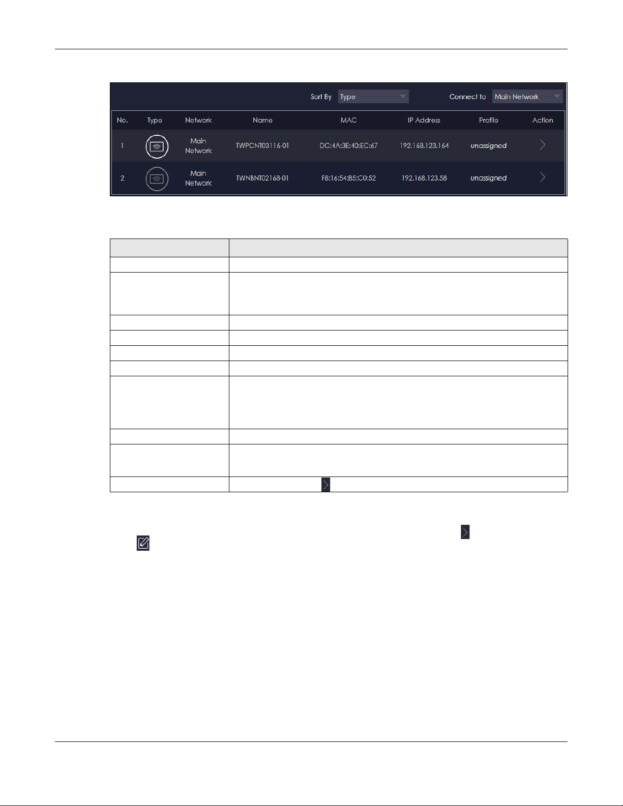
8.2.1 Device Screen
Use this screen to enable parental control, view the parental control rules and schedules.
Click Parental Control > Device to show the following screen.
NBG6818 User’s Guide
57
Chapter 8 Applications
Figure 20 Parental Control > Device
The following table describes the fields in this screen.
Table 8 Parental Control
LABEL DESCRIPTION
Sort By Choose to sort the order of your devices by Type or Name.
Connect to Choose whether you want to show devices that are connected to Main Network or
No. This shows the index number of the rule.
Type The shows the type of device to which this rule applies.
Network This shows the type of network the devices are connected to.
Name This shows the name of the user to which this rule applies.
MAC This field shows the MAC address of the device with the name in the Name field.
IP Address This field displays the IP address relative to the No. field listed above.
Profile This shows the name of the rule that is applied to the device.
devices that are connected Guest Network.
Choose All if you want to show all devices.
Every Ethernet device has a unique MAC (Media Access Control) address which
uniquely identifies a device. The MAC address is assigned at the factory and consists
of six pairs of hexadecimal characters, for example, 00:A0:C5:00:00:02.
If no rule exists, unassigned is showed in this field.
Action Click the Action icon ( ) to configure a rule for the device.
8.2.1.1 Edit Device Detail Screen
Use this screen to configure basic settings for the device. Click the Action icon (), and then the Edit
icon ( ) to show the following screen.
NBG6818 User’s Guide
58
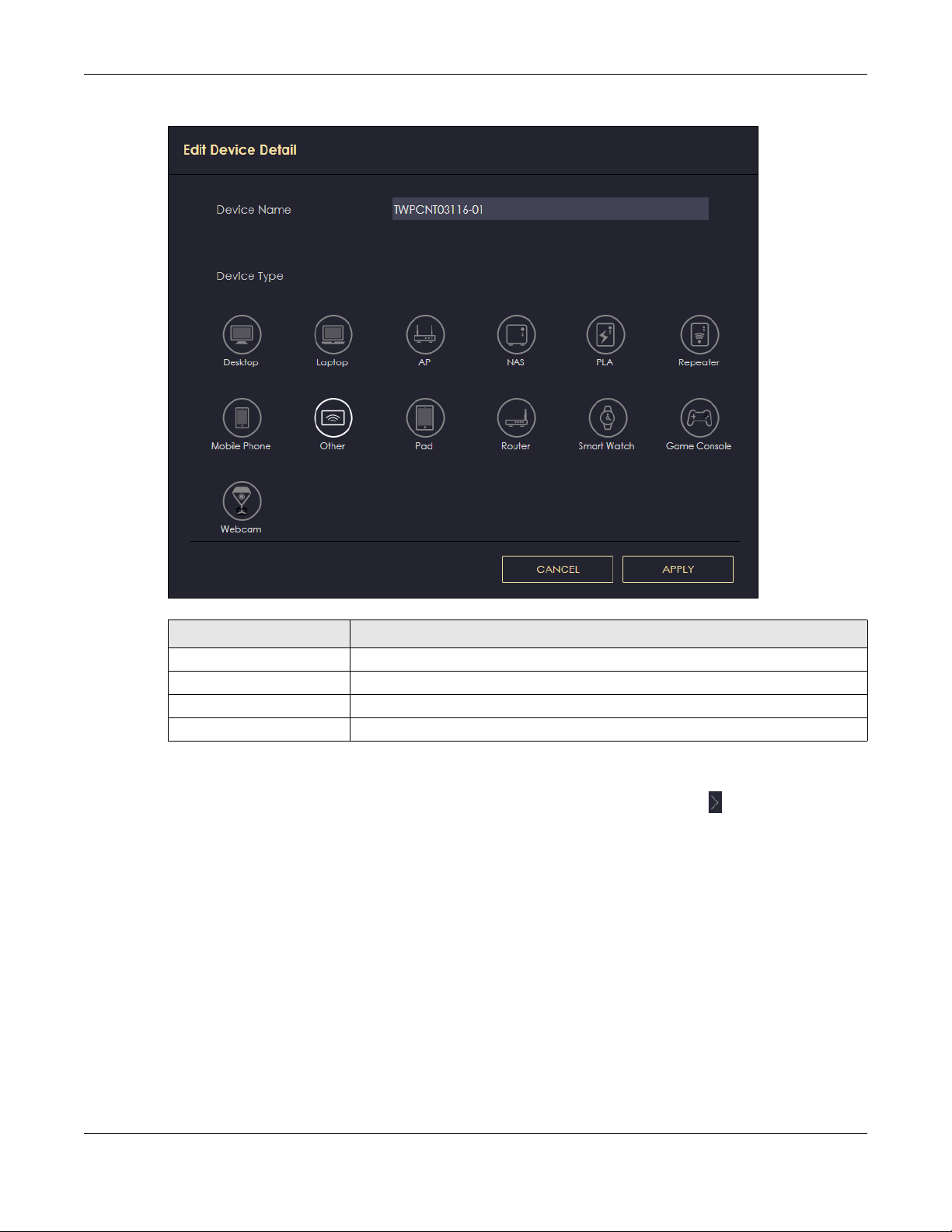
Figure 21 Edit Device Detail
Chapter 8 Applications
Table 9 Edit Device Detail
LABEL DESCRIPTION
Device Name Enter a name for the device to which this rule applies.
Type Choose the type of device to which this rule applies.
Apply Click Apply to save your settings back to the NBG6818.
Cancel Click Cancel to exist the screen without saving.
8.2.1.2 Add New Profile Screen
Use this screen to configure a restricted access schedule. Click the Action icon (), then Add New
Profile to show the following screen.
NBG6818 User’s Guide
59

Figure 22 Add New Profile
Chapter 8 Applications
The following table describes the fields in this screen.
Table 10 Add New Profile
LABEL DESCRIPTION
Profile Name Enter a name for this rule.
Select All Click Select All then deselect the blocks you don’t want or click on blocks
separately to specify days and times to turn the Wireless LAN on or off.
Deselect All Click Deselect All to remove all the wireless LAN scheduling.
Apply Click Apply to save your changes back to the NBG6818.
Back Click Back to exist the screen without saving.
NBG6818 User’s Guide
60

8.2.1.3 Profile Screen
Use this screen to edit or delete an existing rule. Click Parental Control > Profile to show the following
screen.
Figure 23 Parental Control > Profile
The following table describes the fields in this screen.
Table 11 Parental Control > Profile
LABEL DESCRIPTION
Enable/Disable Set the switch to the right ( ) to enable an existing rule. Otherwise, set the
Quick Block Click Quick Block to activate the profile.
Edit Click on the Edit icon to edit an existing rule.
Delete Click on the Delete icon to delete an existing rule.
Chapter 8 Applications
switch to the left ( ).
8.3 OpenVPN Server/Client
OpenVPN is a VPN protocol which is open source and free of charge. It can be used to create a virtual
private network or to interconnect local networks.
It uses OpenSSL encryption library and SSLv3/TLSv1 protocols. This provides high security and anonymity
for all transmitted data.
It also provides faster connection speeds than other VPN protocols.
Note: We do not recommended activating OpenVPN Server and OpenVPN Client at the
same time on your NBG6818.
8.3.1 OpenVPN Server Screen
Use this screen to create an OpenVPN server account. Click the Navigation Panel icon on the top-left
corner ( ).Select OpenVPN Server, and click the OpenVPN Server tab.
NBG6818 User’s Guide
61

Chapter 8 Applications
Figure 24 Example of NBG6818 Acting As VPN Server
Note: You have to enable DDNS in Settings > Internet > Dynamic DNS screen before you can
create an OpenVPN account. See Section 9.8 on page 95 for more information on
Dynamic DNS.
Figure 25 OpenVPN Server
The following table describes the fields in this screen.
Table 12 OpenVPN Server
LABEL DESCRIPTION
OpenVPN Server
Dynamic DNS This field shows the status of your Dynamic DNS. Make sure it shows Enable before
you create an OpenVPN account.
Host Name This field shows the Host Name of your Dynamic DNS account.
Configuration
Status Select Enable to activate your OpenVPN Server account.
Protocol Select the protocol you want to apply to your OpenVPN Server account.
NBG6818 User’s Guide
62

Chapter 8 Applications
Table 12 OpenVPN Server
LABEL DESCRIPTION
Server Port The default server port number is 1194. You can change it if needed. However,
clients connected to this OpenVPN Server account will have to use the same port
number in order to access the server account.
VPN Subnet/ Netmask The fields define the network form which OpenVPN clients can connect to the
Advertise DNS to Clients Select Enable if you want the NBG6818 to broadcast its OpenVPN server to
Key Setting Click the Change Key button if you want to change the key your clients use to
Export Config Click Export Config to export your configuration to an .ovpn file that OpenVPN
Apply Click Apply to save your changes back to the NBG6818.
Cancel Click Cancel to begin configuring this screen afresh.
NBG6818 OpenVPN server.
Enter an IPv4 address and subnet mask.
OpenVPN clients in its VPN network defined previously.
access to your OpenVPN Server account.
You do not need to click Change Key the first time to configure this screen.
Periodically changing the key is recommended, but you must export the new .opvn
configuration file and send it to all OpenVPN clients so that they can they use the
new key.
clients need to connect to the NBG6818 OpenVPN server.
8.3.2 OpenVPN Account Screen
Use the OpenVPN Account List screen to view the basic information of the NBG6818 OpenVPN server.
Use the OpenVPN Account Status screen to view the basic information of clients that are connected to
the NBG6818 OpenVPN server
Note: At the time of writing, up to 16 OpenVPN clients can connect to the NBG6818
OpenVPN server at the same time.
Figure 26 OpenVPN Account
NBG6818 User’s Guide
63

Chapter 8 Applications
The following table describes the fields in this screen.
Table 13 OpenVPN Account
LABEL DESCRIPTION
OpenVPN Account List
No. This is the rule index number.
Username This field displays a name to identify this rule.
Password This field displays a combination of characters and numbers clients need to connect
Client Access Allowed This field displays the interface(s) through which the clients are allowed to connect
Actions Click the icons under Actions to delete or edit an existing OpenVPN account
OpenVPN Account Status
No. This is the number used to identify a client.
Public IP This field displays the public IP of a client.
Private IP This field displays the private IP of a client.
Connected Time This field displays how long a client is connected.
to an account.
to an account.
settings.
Click to delete an existing OpenVPN account.
Click to edit an existing OpenVPN account.
8.3.2.1 OpenVPN Account List-Add Rule Screen
Use this screen to configure your OpenVPN account settings.
Figure 27 OpenVPN Account LIst-Add Rule
The following table describes the fields in this screen.
Table 14 OpenVPN Account List-Add Rule
LABEL DESCRIPTION
User Name Enter 1-32 single-byte printable ASCII characters, but <>^$& are not allowed.
Password Enter 1-32 single-byte printable ASCII characters, but <>^$& are not allowed.
Client Access Allowed Select the interface(s) through which the clients are allowed to connect to your
account.
NBG6818 User’s Guide
64

Table 14 OpenVPN Account List-Add Rule
LABEL DESCRIPTION
Apply Click Apply to save your changes back to the NBG6818.
Cancel Click Cancel to exist this screen without saving.
8.3.3 OpenVPN Client Screen
Use the OpenVPN Server List in this screen to view the basic information of the OpenVPN Server
accounts that you are connected to when the NBG6818 functions as an OpenVPN client.
Figure 28 Example of NBG6818 Acting As VPN Client
Chapter 8 Applications
Note: You can only connect to one server at a time.
Figure 29 OpenVPN Client
The following table describes the fields in this screen.
Table 15 OpenVPN Client
LABEL DESCRIPTION
No. This is the rule index number.
Description This field displays a name to identify this rule.
Enable VPN on This field displays the interface(s) through which your NBG6818 are allowed to
connect to an OpenVPN Server account.
Connected IP This field displays the IP address of the OpenVPN Server account your NBG6818 is
connected to.
NBG6818 User’s Guide
65

Chapter 8 Applications
Table 15 OpenVPN Client
LABEL DESCRIPTION
Active Slide the switch to the right ( ) to activate your connection to an OpenVPN
Server account.
Actions Click the icons under Actions to delete or edit an existing OpenVPN Server account
settings.
Click to delete an existing OpenVPN Server account.
Click to edit an existing OpenVPN Server account.
8.3.3.1 OpenVPN Server List-Add Rule Screen
Use this screen to add an OpenVPN Server Account that you want your NBG6818 to connect to.
Figure 30 OpenVPN Server List-Add Rule
The following table describes the fields in this screen.
Table 16 OpenVPN Server List-Add Rule
LABEL DESCRIPTION
Description Enter 1-32 single-byte printable ASCII characters, but <>^$& are not allowed.
User Name Enter the User Name of the OpenVPN Server account you want to connect to.
Password Enter the Password of the OpenVPN Server account you want to connect to.
Import .ovpn file Import an .ovpn file that you get from the OpenVPN Server that you want to
connect to.
Note: Do not import the .ovpn file you get from your NBG6818’s OpenVPN
Server.
Enable VPN on Select the interface(s) that are allowed by the OpenVPN Server account you want
to connect to.
NBG6818 User’s Guide
66

Table 16 OpenVPN Server List-Add Rule
LABEL DESCRIPTION
Apply Click Apply to save your changes back to the NBG6818.
Cancel Click Cancel to exist this screen without saving.
8.4 USB Application
8.4.1 SAMBA Server Screen
Use this screen to set up file-sharing via the NBG6818 using Windows Explorer or the workgroup name.
You can also configure the workgroup name and create file-sharing user accounts.
Click USB Application > SAMBA to show the following screen.
Figure 31 USB Application > SAMBA
Chapter 8 Applications
The following table describes the labels in this screen.
Table 17 USB Application > SAMBA
LABEL DESCRIPTION
SAMBA Setup
Enable SAMBA Select this to enable file sharing through the NBG6818 using Windows Explorer or by browsing
Name Specify the name to identify the NBG6818 in a work group.
to your work group.
NBG6818 User’s Guide
67

Chapter 8 Applications
Table 17 USB Application > SAMBA (continued)
LABEL DESCRIPTION
Work Group You can add the NBG6818 to an existing or a new workgroup on your network. Enter the
name of the workgroup which your NBG6818 automatically joins. You can set the NBG6818’s
workgroup name to be exactly the same as the workgroup name to which your computer
belongs to.
Note: The NBG6818 will not be able to join the workgroup if your local area
network has restrictions set up that do not allow devices to join a
workgroup. In this case, contact your network administrator.
Description Enter the description of the NBG6818 in a work group.
Require username
and password
User Accounts Before you can share files you need a user account. Configure the following fields to set up
No. This is the index number of the user account.
Status This field displays whether a user account is activated or not.
User Name This field displays the user name that will be allowed to access the shared files.
USB This field displays the user’s access rights to the USB storage device which is connected to
Actions Click the icons under Actions to delete or edit a port forwarding rule.
Select Yes to need a user account for access to the connected USB stick from any
computer. Otherwise, select No.
a file-sharing account.
the NBG6818’s USB port.
Click to delete an existing trigger port settings.
Click to edit an existing trigger port settings.
Apply Click Apply to save your changes back to the NBG6818.
Cancel Click Cancel to begin configuring this screen afresh.
8.4.1.1 Add SAMBA Account Screen
Use this screen to configure settings for a SAMBA account.
Click USB Application > SAMBA > Add Rule to show the following screen.
NBG6818 User’s Guide
68

Chapter 8 Applications
Figure 32 USB Application > SAMBA > Add Rule
The following table describes the labels in this screen.
Table 18 USB Application > SAMBA > Add Rule
LABEL DESCRIPTION
Status Select Enable to enable the account.
User Name Enter a user name that will be allowed to access the shared files. You can enter up
Password Enter the password used to access the shared files. You can enter up to 20
USB Specify the user’s access rights to the USB storage device which is connected to the
Apply Click Apply to save your changes back to the NBG6818.
Cancel Click Cancel to exist the screen without saving.
8.4.2 FTP Server Screen
Select Disable to disable the account.
to 20 characters. Only letters and numbers allowed.
characters. Only letters and numbers are allowed. The password is case sensitive.
NBG6818’s USB port.
Read & Write - The user has read and write rights, meaning that the user can create
and edit the files on the connected USB device.
Read - The user has read rights only and can not create or edit the files on the
connected USB device.
None - The user cannot access the files on the USB device(s) connected to the USB
port.
Use this screen to set up file sharing via the NBG6818 using FTP and create user accounts.
Click USB Application > FTP to show the following screen.
NBG6818 User’s Guide
69

Chapter 8 Applications
Figure 33 USB Application > FTP
The following table describes the labels in this screen.
Table 19 Expert Mode > Applications > File Sharing > FTP
LABEL DESCRIPTION
Enable FTP Select this to enable the FTP server on the NBG6818 for file sharing using FTP.
Port You may change the server port number for FTP if needed, however you must use the same
port number in order to use that service for file sharing.
User Accounts Before you can share files you need a user account. Configure the following fields to set up
a file-sharing account.
No. This is the index number of the user account.
Status This field displays whether a user account is activated or not. Select the check box to
User Name This field displays the user name that will be allowed to access the shared files.
USB This field displays the user’s access rights to the USB storage device which is connected to
Upstream
Bandwidth
Downstream
Bandwidth
Actions Click the icons under Actions to delete or edit a port forwarding rule.
Apply Click Apply to save your changes back to the NBG6818.
Cancel Click Cancel to begin configuring this screen afresh.
enable the account. Clear the check box to disable the account.
the NBG6818’s USB port.
This field shows the maximum bandwidth (in Kbps) allowed for incoming FTP traffic.
This field shows the maximum bandwidth (in Kbps) allowed for outgoing FTP traffic.
Click to delete an existing trigger port settings.
Click to edit an existing trigger port settings.
8.4.2.1 Add FTP Account Screen
Use this screen to configure settings for a FTP account.
Click USB Application > FTP > Add Rule to show the following screen.
NBG6818 User’s Guide
70

Chapter 8 Applications
Figure 34 USB Application > FTP > Add Rule
The following table describes the labels in this screen.
Table 20 USB Application > FTP > Add Rule
LABEL DESCRIPTION
Status Select Enable to enable the account.
Select Disable to disable the account.
User Name
Password
USB
Upstream Bandwidth
Downstream Bandwidth
Apply
Cancel
Enter a user name that will be allowed to access the shared files. You can enter up
to 20 characters. Only letters and numbers allowed.
Enter the password used to access the shared files. You can enter up to 20
characters. Only letters and numbers are allowed. The password is case sensitive.
Specify the user’s access rights to the USB storage device which is connected to the
NBG6818’s USB port.
Read & Write - The user has read and write rights, meaning that the user can create
and edit the files on the connected USB device.
Read - The user has read rights only and can not create or edit the files on the
connected USB device.
None - The user cannot access the files on the USB device(s) connected to the USB
port.
Enter the maximum bandwidth (in Kbps) allowed for incoming FTP traffic.
Enter the maximum bandwidth (in Kbps) allowed for outgoing FTP traffic.
Click Apply to save your changes back to the NBG6818.
Click Cancel to exist the screen without saving.
8.4.3 USB Media Sharing Screen
Use this screen to configure settings for media sharing.
NBG6818 User’s Guide
71

Chapter 8 Applications
The media server feature lets anyone on your network play video, music, and photos from the USB
storage device connected to your NBG6818 without having to copy them to another computer. The
NBG6818 can function as a DLNA-compliant media server, where the NBG6818 streams files to DLNAcompliant media clients like Windows Media Player.
The Digital Living Network Alliance (DLNA) is a group of personal computer and electronics companies
that works to make products compatible in a home network.
The NBG6818 media server enables you to:
• Publish all share folders for everyone to play media files in the USB storage device connected to the
NBG6818.
• Use hardware-based media clients like the DMA-2500 to play the files.
Note: Anyone on your network can play the media files in the published folders. No user
name and password nor other form of security is required.
Figure 35 Media Server Overview
Click USB Application > USB Media Sharing to show the following screen.
Figure 36 USB Application > USB Media Sharing
NBG6818 User’s Guide
72

Chapter 8 Applications
The following table describes the labels in this screen.
Table 21 USB Application > USB Media Sharing
LABEL DESCRIPTION
USB Media Sharing
Media Server
(DLNA) Setup
Share Media Type Permission
Photo/Music/Video Select the media type that you want to share on the USB device connected to the
Rescan Media Control
Rescan Click this button to have the NBG6818 scan the media files on the connected USB device
Apply Click Apply to save your changes back to the NBG6818.
Cancel Click Cancel to begin configuring this screen afresh.
Choose Enable to have the NBG6818 function as a DLNA-compliant media server.
Otherwise, choose Disable.
NBG6818’s USB port.
and do indexing of the file list again so that DLNA clients can find the new files if any.
8.5 Access Your Shared Files From a Computer
8.5.1 Using Windows Explorer
You can use Windows Explorer to access the file storage devices connected to the NBG6818.
Note: The examples in this User’s Guide show you how to use Microsoft’s Windows 7 to browse
your shared files. Refer to your operating system’s documentation for how to browse
your file structure.
Open Windows Explorer to access usb1 using the Windows Explorer browser.
In the Windows Explorer’s address bar type a double backslash “\\” followed by the IP address of the
NBG6818 (the default IP address of the NBG6818 is 192.168.123.1) and press [ENTER]. The share folder
usb1 is available.
NBG6818 User’s Guide
73
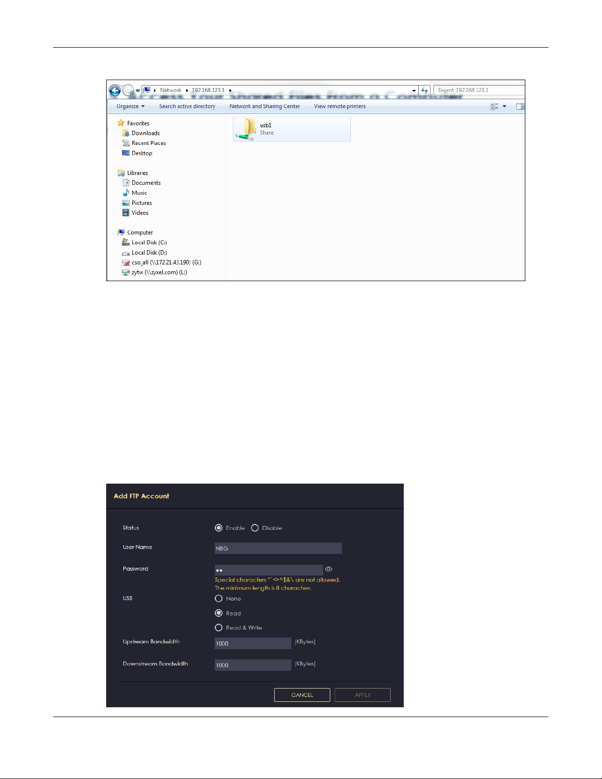
Chapter 8 Applications
Figure 37 USB1
Once you access usb1 via your NBG6818, you do not have to relogin unless you restart your computer.
8.5.2 Using FTP Program
Here is how to use an FTP program to access a file storage device connected to the NBG6818’s USB
port.
Note: This example uses the FileZilla FTP program to browse your shared files.
1 Download FileZilla and install the FTP software to your computer
2 Go to USB Application > FTP. On the FTP Setup screen, click Add Rule to go to the Add FTP Account
screen. You can use this screen to create a set of User Name and Password and set up USB rules for file
sharing. (See more information at Section 8.4.2 on page 69.) Click Apply to save the changes.
Figure 38 Add FTP Account
NBG6818 User’s Guide
74

Chapter 8 Applications
3 You can click the Edit or Delete icon to edit or delete the rules.
Figure 39 Add Rule Edit
4 Open FileZilla, enter the Host IP address of the NBG6818 (the default IP address is 192.168.123.1), the
Username and Password, and the port number 21, and then click Quickconnect. A screen asking for
password authentication appears.
File Sharing via Windows Explore r
NBG6818 User’s Guide
75

Chapter 8 Applications
5 Once you log in the USB device displays in the usb1 folder.
NBG6818 User’s Guide
76
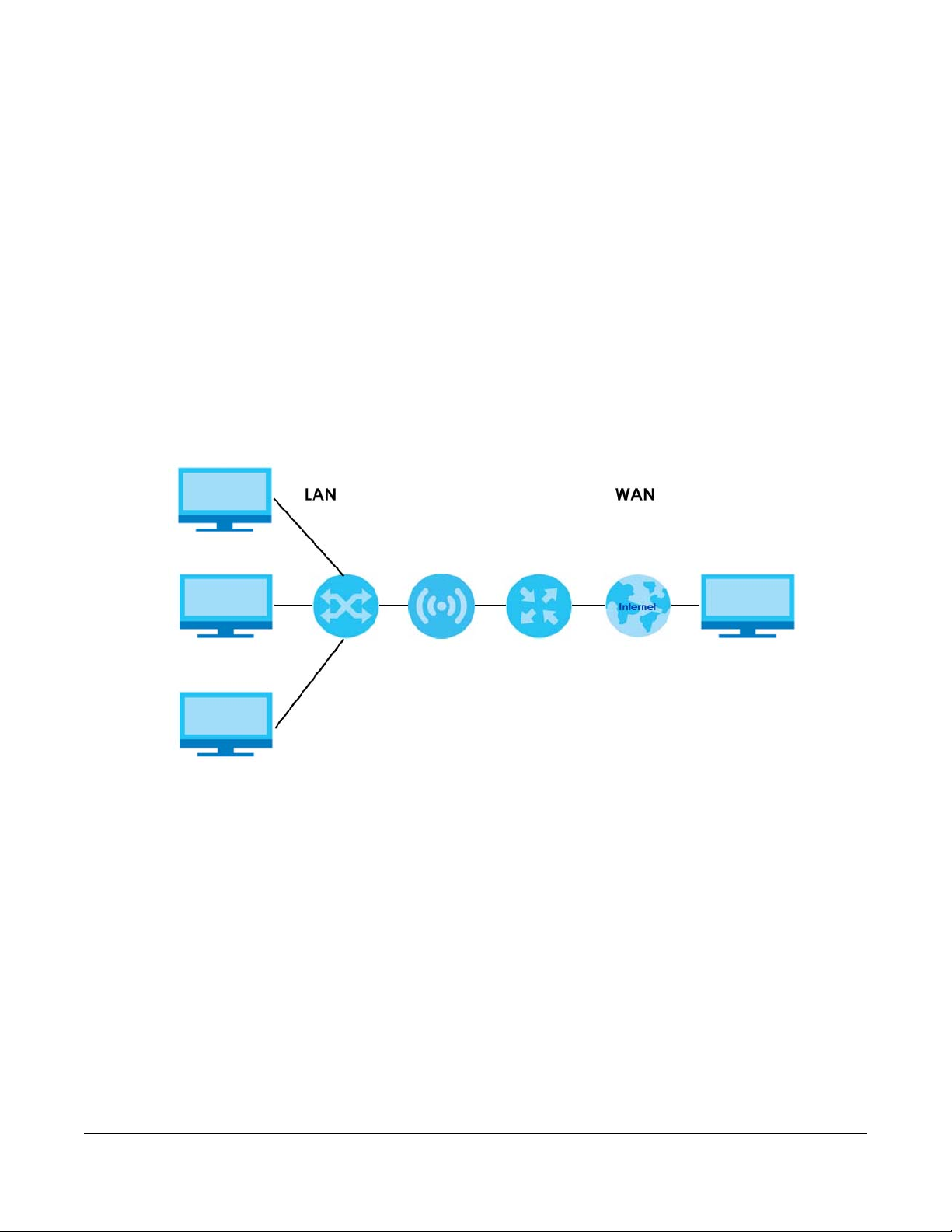
9.1 Overview
This chapter discusses the NBG6818’s WAN screens. Use these screens to configure your NBG6818 for
Internet access.
A WAN (Wide Area Network) connection is an outside connection to another network or the Internet. It
connects your private networks such as a LAN (Local Area Network) and other networks, so that a
computer in one location can communicate with computers in other locations.
Figure 40 LAN and WAN
CHAPTER 9
WAN
Note: Features in this chapter are not available if you are using bridge mode.
9.2 What You Can Do
• Use the Internet Connection screen to enter your ISP information and set how the computer acquires
its IP, DNS and WAN MAC addresses (Section 9.4 on page 79).
• Use the NAT & Port Forwarding screen to enable NAT, set a default server and change your NBG6818’s
port forwarding settings (Section 9.5 on page 87).
• Use the Passthrough screen to configure your NBG6818’s ALGs and VPN pass-through settings (Section
9.6 on page 91)
• Use the Port Trigger screen to configure your NBG6818’s trigger port settings (Section 9.7 on page 92).
• Use the Dynamic DNS screen to change your NBG6818’s DDNS settings (Section 9.8 on page 95).
• Use the UPnP screen to enable UPnP on your NBG6818 (Section 9.9 on page 96).
NBG6818 User’s Guide
77

Chapter 9 WAN
9.3 What You Need To Know
The information in this section can help you configure the screens for your WAN connection, as well as
enable/disable some advanced features of your NBG6818.
9.3.1 Configuring Your Internet Connection
Encapsulation Method
Encapsulation is used to include data from an upper layer protocol into a lower layer protocol. To set up
a WAN connection to the Internet, you need to use the same encapsulation method used by your ISP
(Internet Service Provider). If your ISP offers a dial-up Internet connection using PPPoE (PPP over
Ethernet) or PPTP (Point-to-Point Tunneling Protocol), they should also provide a username and password
(and service name) for user authentication.
WAN IP Address
The WAN IP address is an IP address for the NBG6818, which makes it accessible from an outside
network. It is used by the NBG6818 to communicate with other devices in other networks. It can be static
(fixed) or dynamically assigned by the ISP each time the NBG6818 tries to access the Internet.
If your ISP assigns you a static WAN IP address, they should also assign you the subnet mask and DNS
server IP address(es) (and a gateway IP address if you use the Ethernet or ENET ENCAP encapsulation
method).
DNS Server Address Assignment
Use Domain Name System (DNS) to map a domain name to its corresponding IP address and vice versa,
for instance, the IP address of www.zyxel.com is 204.217.0.2. The DNS server is extremely important
because without it, you must know the IP address of a computer before you can access it.
The NBG6818 can get the DNS server addresses in the following ways.
1 The ISP tells you the DNS server addresses, usually in the form of an information sheet, when you sign up.
If your ISP gives you DNS server addresses, manually enter them in the DNS server fields.
2 If your ISP dynamically assigns the DNS server IP addresses (along with the NBG6818’s WAN IP address),
set the DNS server fields to get the DNS server address from the ISP.
WAN MAC Address
The MAC address screen allows users to configure the WAN port's MAC address by either using the
factory default or cloning the MAC address from a computer on your LAN. Choose Factory Default to
select the factory assigned default MAC Address.
Otherwise, click Clone the computer's MAC address - IP Address and enter the IP address of the
computer on the LAN whose MAC you are cloning. Once it is successfully configured, the address will be
copied to configuration file. It is recommended that you clone the MAC address prior to hooking up the
WAN Port.
NBG6818 User’s Guide
78
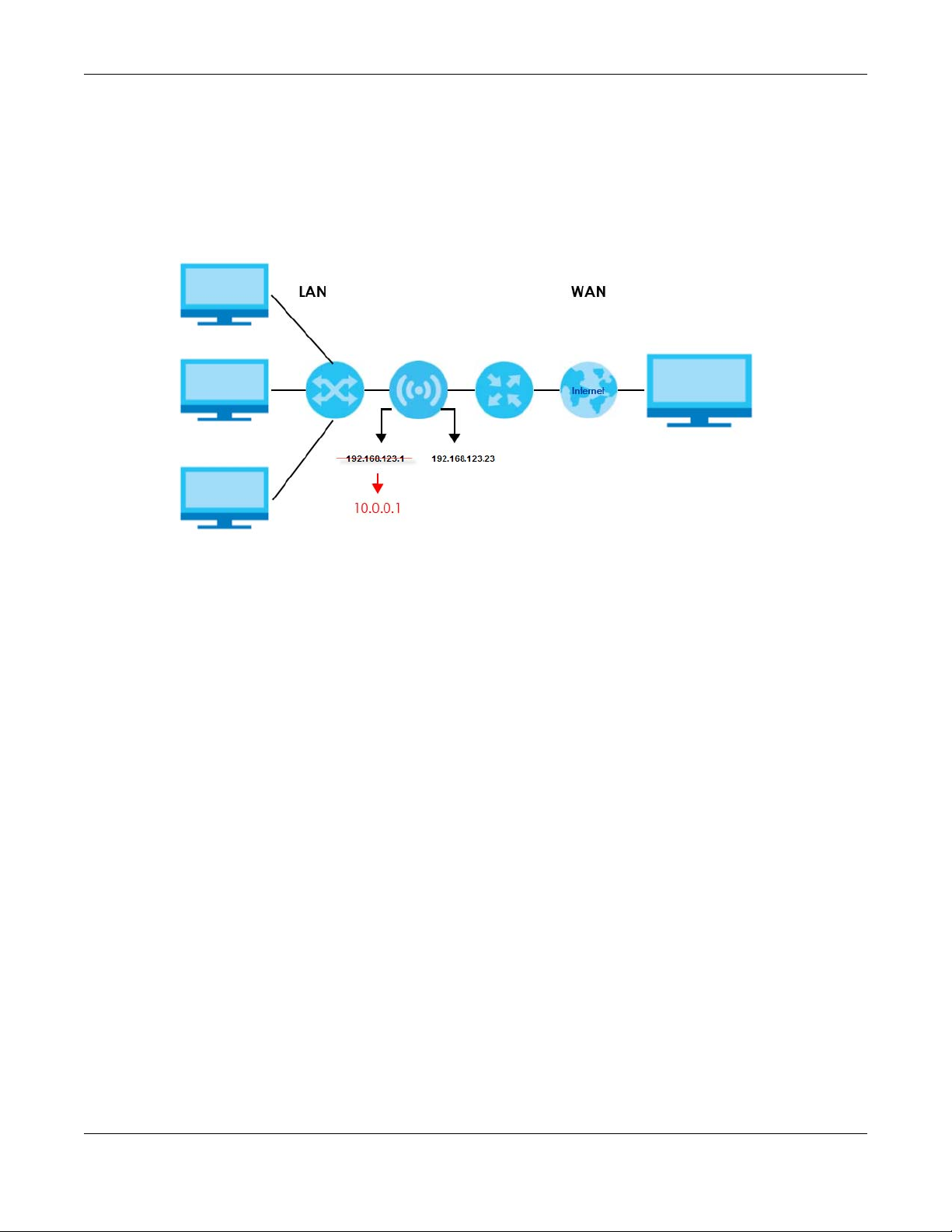
Chapter 9 WAN
Auto-IP Change
When the NBG6818 gets a WAN IP address or a DNS server IP address which is in the same subnet as the
LAN IP address 192.168.123.1, Auto-IP-Change allows the NBG6818 to change its LAN IP address to
10.0.0.1 automatically. If the NBG6818’s original LAN IP address is 10.0.0.1 and the WAN IP address is in
the same subnet, such as 10.0.0.3, the NBG6818 switches to use 192.168.123.1 as its LAN IP address.
Figure 41 Auto-IP-Change Example
Auto-IP-Change only works under the following conditions:
• The NBG6818 must be in Standard Mode (see Section 13.7 on page 137 for more information) for Auto-
IP-Change to become active.
• The NBG6818 is set to receive a dynamic WAN IP address.
9.4 Internet Connection Screen
Use this screen to change your NBG6818’s Internet access settings. The screen varies depending on the
encapsulation method you select. Click Settings > Internet > Internet Connection.
9.4.1 IPoE Encapsulation
This screen displays when you select IPoE encapsulation.
NBG6818 User’s Guide
79

Chapter 9 WAN
Figure 42 Settings > Internet > Internet Connection: IPoE (IPv4 Only)
The following table describes the labels in this screen.
Table 22 Network > WAN > Internet Connection: IPoE Encapsulation
LABEL DESCRIPTION
Internet Connection
Internet Service
Provider Type
IPv4 / IPv6 Select IPv4 Only if you want the NBG6818 to run IPv4 only.
IPv4 Address
Automatic IP (DHCP) Select this option If your ISP did not assign you a fixed IP address. This is the default selection.
You must choose the IPoE option when the WAN port is used as a regular Ethernet.
Select Dual Stack to allow the NBG6818 to run IPv4 and IPv6 at the same time.
NBG6818 User’s Guide
80

Chapter 9 WAN
Table 22 Network > WAN > Internet Connection: IPoE Encapsulation (continued)
LABEL DESCRIPTION
Static IP Select this option If the ISP assigned a fixed IP address.
IP Address Enter your WAN IP address in this field if you selected Static IP Address .
IP Subnet Mask Enter the Subnet Mask in this field.
Gateway Enter a gateway IP address (if your ISP gave you one) in this field.
MTU Size Enter the MTU (Maximum Transmission Unit) size for each packet. If a larger packet arrives,
the NBG6818 divides it into smaller fragments.
DNS Server
First DNS Server
Second DNS Server
Third DNS Server
WAN MAC Address
Once the WAN MAC address is successfully configured, the address will be copied to the configuration file. It will
not change unless you change the setting or upload a different configuration file.
Factory Default Select this option to have the WAN interface use the factory assigned default MAC address.
Clone My
Computer’s MAC
Address
Set WAN MAC
Address
LAN & WAN Subnet Conflict
Automatically
change the LAN IP
IPv6 Address
Select User-Defined if you have the IP address of a DNS server. Enter the DNS server's IP
address in the field to the right.
Select None if you do not want to configure DNS servers. If you do not configure a DNS
server, you must know the IP address of a computer in order to access it.
By default, the NBG6818 uses the factory assigned MAC address to identify itself.
Select this option to have the WAN interface use a different MAC address by cloning the
MAC address of another device or computer. Enter the IP address of the device or
computer whose MAC you are cloning.
Select this option to have the WAN interface use a manually specified MAC address. Enter
the MAC address in the fields.
Select this option to have the NBG6818 change its LAN IP address to 10.0.0.1 or
192.168.123.1 accordingly when the NBG6818 gets a dynamic WAN IP address in the same
subnet as the LAN IP address. See Section 9.3.1 on page 78 for more information.
The NAT, DHCP server and firewall functions on the NBG6818 are still available in this mode.
This section is NOT available when you select IPv4 Only in the IPv4/IPv6 field.
Automatic IP (DHCP) Select this option if you want to obtain an IPv6 address from a DHCPv6 server.
•Select DUID-LL (Default) to have the NBG6818 use DUID-LL (DUID Based on Link-layer
Address) for identification when exchanging DHCPv6 messages.
•Select DUID-LLT to have the NBG6818 use DUID-LLT (DUID Based on Link-layer Address
Plus Time) for identification when exchanging DHCPv6 messages.
Static IP Address Select this option if you have a fixed IPv6 address assigned by your ISP.
IPv6 Address Enter the IPv6 address assigned by your ISP.
Prefix length Enter the address prefix length to specify how many most significant bits in an IPv6 address
compose the network address.
Gateway Enter the IPv6 address of the next-hop gateway. The gateway helps forward packets to
Link Local Only Select this option to use the link-local address which uniquely identifies a device on the
IPv6 DNS Server
This section is NOT available when you select IPv4 Only in the IPv4/IPv6 field.
their destinations.
local network (the LAN).
NBG6818 User’s Guide
81

Table 22 Network > WAN > Internet Connection: IPoE Encapsulation (continued)
LABEL DESCRIPTION
First DNS Server
Second DNS Server
Third DNS Server
Apply Click Apply to save your changes back to the NBG6818.
Cancel Click Cancel to begin configuring this screen afresh.
Select User-Defined and enter the IPv6 DNS server address assigned by the ISP to have the
NBG6818 use the IPv6 DNS server addresses you configure manually.
Select None if you do not want to configure DNS servers. If you do not configure a DNS
server, you must know the IPv6 address of a computer in order to access it.
9.4.2 PPPoE Encapsulation
The NBG6818 supports PPPoE (Point-to-Point Protocol over Ethernet). PPPoE is an IETF standard (RFC 2516)
specifying how a personal computer (PC) interacts with a broadband modem (DSL, cable, wireless,
etc.) connection. The PPP over Ethernet option is for a dial-up connection using PPPoE.
For the service provider, PPPoE offers an access and authentication method that works with existing
access control systems (for example Radius).
One of the benefits of PPPoE is the ability to let you access one of multiple network services, a function
known as dynamic service selection. This enables the service provider to easily create and offer new IP
services for individuals.
Chapter 9 WAN
Operationally, PPPoE saves significant effort for both you and the ISP or carrier, as it requires no specific
configuration of the broadband modem at the customer site.
By implementing PPPoE directly on the NBG6818 (rather than individual computers), the computers on
the LAN do not need PPPoE software installed, since the NBG6818 does that part of the task.
Furthermore, with NAT, all of the LANs’ computers will have access.
NBG6818 User’s Guide
82

Chapter 9 WAN
This screen displays when you select PPPoE encapsulation.
Figure 43 Settings > Internet > Internet Connection: PPPoE (IPv4 Only)
The following table describes the labels in this screen.
Table 23 Network > WAN > Internet Connection: PPPoE Encapsulation
LABEL DESCRIPTION
Internet Connection
Internet Service
Provider Type
IPv4 / IPv6 Select IPv4 Only if you want the NBG6818 to run IPv4 only.
PPPoE Username Type the user name given to you by your ISP.
Select PPPoE if you connect to your Internet via dial-up.
Select Dual Stack to allow the NBG6818 to run IPv4 and IPv6 at the same time.
NBG6818 User’s Guide
83

Chapter 9 WAN
Table 23 Network > WAN > Internet Connection: PPPoE Encapsulation (continued)
LABEL DESCRIPTION
Password Type the password associated with the user name above.
MTU Size Enter the Maximum Transmission Unit (MTU) or the largest packet size per frame that your
NBG6818 can receive and process.
Service Name Enter the PPPoE service name specified in the ISP account.
DNS Server
First DNS Server
Second DNS Server
Third DNS Server
WAN IP Address Assignment
Obtained from ISP Select this option If your ISP did not assign you a fixed IP address. This is the default selection.
Fixed IP Select this option and enter your WAN IP address if the ISP assigned a fixed IP address.
WAN MAC Address
The MAC address section allows users to configure the WAN port's MAC address by using the NBG6818’s MAC
address, copying the MAC address from a computer on your LAN or manually entering a MAC address.
Factory Default Select Factory default to use the factory assigned default MAC Address.
Clone My
Computer’s MAC
Address
Set WAN MAC
Address
IPv6 Address
This section is NOT available when you select IPv4 Only in the IPv4/IPv6 field.
Automatic IP
(DHCP)
Static IP Address Select this option if you have a fixed IPv6 address assigned by your ISP.
IPv6 Address Enter the IPv6 address assigned by your ISP.
Prefix length Enter the address prefix length to specify how many most significant bits in an IPv6 address
Gateway Enter the IPv6 address of the next-hop gateway. The gateway helps forward packets to their
Link Local Only Select this option to use the link-local address which uniquely identifies a device on the local
IPv6 DNS Server
This section is NOT available when you select IPv4 Only in the IPv4/IPv6 field.
First DNS Server
Second DNS Server
Third DNS Server
LAN & WAN Subnet Conflict
Select User-Defined if you have the IP address of a DNS server. Enter the DNS server's IP
address in the field to the right.
Select None if you do not want to configure DNS servers. If you do not configure a DNS server,
you must know the IP address of a computer in order to access it.
Select Clone the computer's MAC address - IP Address and enter the IP address of the
computer on the LAN whose MAC you are cloning.
Select this option and enter the MAC address you want to use.
Select this option if you want to obtain an IPv6 address from a DHCPv6 server.
• Select DUID-LL (Default) to have the NBG6818 use DUID-LL (DUID Based on Link-layer
Address) for identification when exchanging DHCPv6 messages.
• Select DUID-LLT to have the NBG6818 use DUID-LLT (DUID Based on Link-layer Address Plus
Time) for identification when exchanging DHCPv6 messages.
compose the network address.
destinations.
network (the LAN).
Select User-Defined and enter the IPv6 DNS server address assigned by the ISP to have the
NBG6818 use the IPv6 DNS server addresses you configure manually.
Select None if you do not want to configure DNS servers. If you do not configure a DNS server,
you must know the IPv6 address of a computer in order to access it.
NBG6818 User’s Guide
84
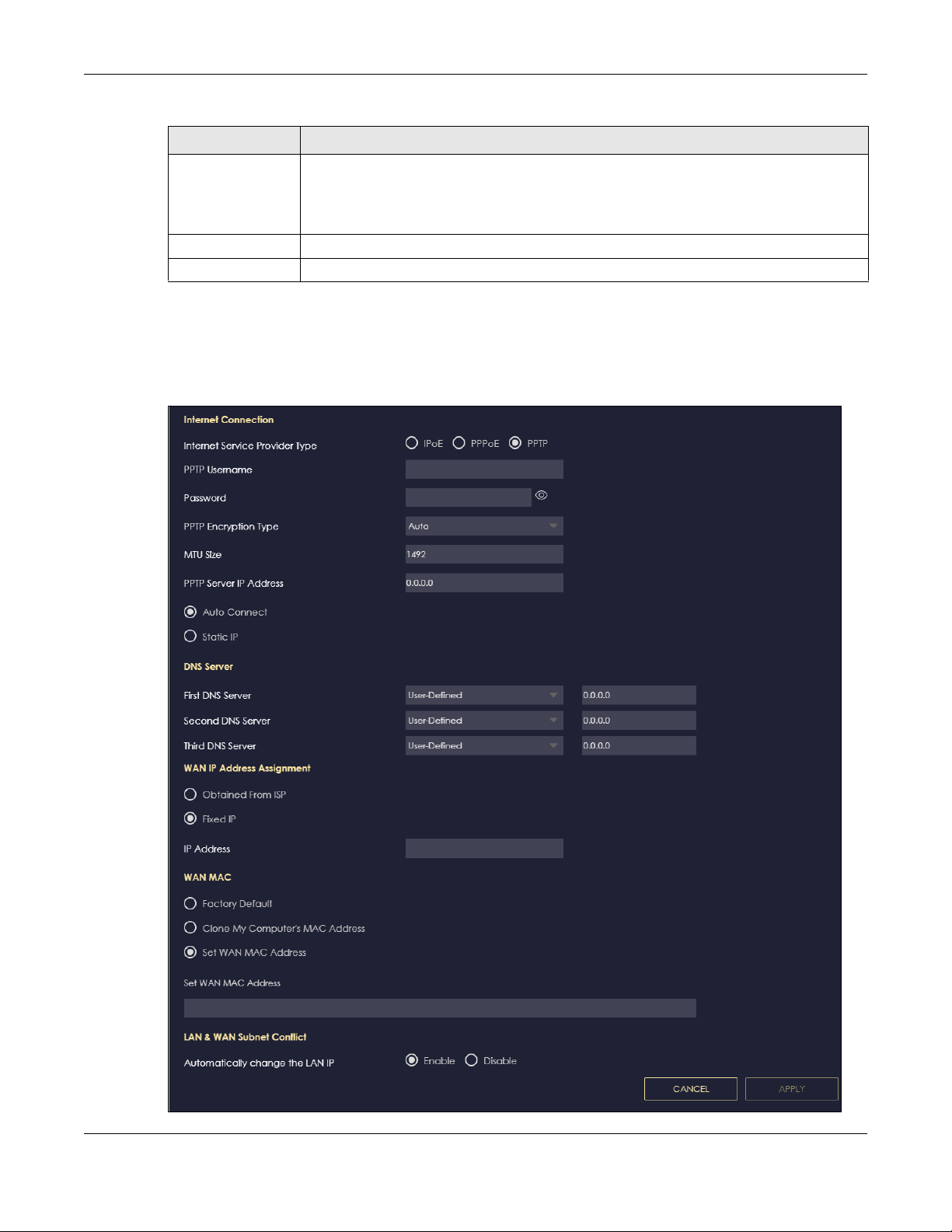
Table 23 Network > WAN > Internet Connection: PPPoE Encapsulation (continued)
LABEL DESCRIPTION
Automatically
change the LAN IP
Apply Click Apply to save your changes back to the NBG6818.
Cancel Click Cancel to begin configuring this screen afresh.
Select this option to have the NBG6818 change its LAN IP address to 10.0.0.1 or 192.168.123.1
accordingly when the NBG6818 gets a dynamic WAN IP address in the same subnet as the
LAN IP address. See Section 9.3.1 on page 78 for more information.
The NAT, DHCP server and firewall functions on the NBG6818 are still available in this mode.
9.4.3 PPTP Encapsulation
This screen displays when you select PPTP encapsulation.
Figure 44 Settings > Internet > Internet Connection: PPTP (IPv4 Only)
Chapter 9 WAN
NBG6818 User’s Guide
85

Chapter 9 WAN
The following table describes the labels in this screen.
Table 24 Network > WAN > Internet Connection: PPTP Encapsulation
LABEL DESCRIPTION
Internet Connection
Internet Service
Provider Type
PPTP Username Enter the user name given to you by your ISP.
Password Enter the password associated with the user name above.
PPTP Encryption Type Use the drop-down list box to select the type of Microsoft Point-to-Point Encryption (MPPE).
MTU Size Enter the MTU (Maximum Transmission Unit) size for each packet. If a larger packet arrives,
PPTP Server IP
Address
Auto Connect Select this radio button if the PPTP server did not assign you a fixed IP address.
Static IP Select this radio button if the PPTP server assigned an IP address for your Internet
IP Address Enter the IP address provided by the PPTP server.
IP Subnet Mask Enter the IP subnet mask in this field.
Gateway Enter the gateway IP address in this field.
DNS Server
First DNS Server
Second DNS Server
Third DNS Server
WAN IP Address Assignment
Obtained from ISP Select this option If your ISP did not assign you a fixed IP address. This is the default selection.
Fixed IP Select this option If the ISP assigned a fixed IP address.
IP Address Enter your WAN IP address in this field if you selected IP Address.
WAN MAC Address
Select PPTP if you want to connect the Internet via point to point tunneling protocol.
Options are:
Auto - This ISP account adjusts the encryption type automatically.
None - This ISP account does not use MPPE.
40 - This ISP account uses 40-bit MPPE.
128 - This ISP account uses 128-bit MMPE.
the NBG6818 divides it into smaller fragments.
Enter the IP address of the PPTP server.
connection.
Select User-Defined if you have the IP address of a DNS server. Enter the DNS server's IP
address in the field to the right.
Select None if you do not want to configure DNS servers. If you do not configure a DNS
server, you must know the IP address of a computer in order to access it.
Once the WAN MAC address is successfully configured, the address will be copied to the configuration file. It will
not change unless you change the setting or upload a different configuration file.
Factory Default Select this option to have the WAN interface use the factory assigned default MAC address.
Clone My
Computer’s MAC
Address
Set WAN MAC
Address
LAN & WAN Subnet Conflict
By default, the NBG6818 uses the factory assigned MAC address to identify itself.
Select this option to have the WAN interface use a different MAC address by cloning the
MAC address of another device or computer. Enter the IP address of the device or
computer whose MAC you are cloning.
Select this option to have the WAN interface use a manually specified MAC address. Enter
the MAC address in the fields.
NBG6818 User’s Guide
86

Chapter 9 WAN
Table 24 Network > WAN > Internet Connection: PPTP Encapsulation (continued)
LABEL DESCRIPTION
Automatically
change the LAN IP
Apply Click Apply to save your changes back to the NBG6818.
Cancel Click Cancel to begin configuring this screen afresh.
Select this option to have the NBG6818 change its LAN IP address to 10.0.0.1 or
192.168.123.1 accordingly when the NBG6818 gets a dynamic WAN IP address in the same
subnet as the LAN IP address. See Section 9.3.1 on page 78 for more information.
The NAT, DHCP server and firewall functions on the NBG6818 are still available in this mode.
9.5 NAT & Port Forwarding Screen
Use Port Forwarding to forward incoming service requests from the Internet to the server(s) on your local
network. Port forwarding is commonly used when you want to host online gaming, P2P file sharing, or
other servers on your network.
You may enter a single port number or a range of port numbers to be forwarded, and the local IP
address of the desired server. The port number identifies a service; for example, web service is on port 80
and FTP on port 21. In some cases, such as for unknown services or where one server can support more
than one service (for example both FTP and web service), it might be better to specify a range of port
numbers. You can allocate a server IP address that corresponds to a port or a range of ports.
Note: TCP port 7547 is reserved for system use.
Note: Many residential broadband ISP accounts do not allow you to run any server processes
(such as a Web or FTP server) from your location. Your ISP may periodically check for
servers and may suspend your account if it discovers any active services at your
location. If you are unsure, refer to your ISP.
Configuring Servers Behind Port Forwarding (Example)
Let's say you want to assign ports 21-25 to one FTP, Telnet and SMTP server (A in the example), port 80 to
another (B in the example) and assign a default server IP address of 192.168.123.35 to a third (C in the
example). You assign the LAN IP addresses and the ISP assigns the WAN IP address. The NAT network
appears as a single host on the Internet.
NBG6818 User’s Guide
87
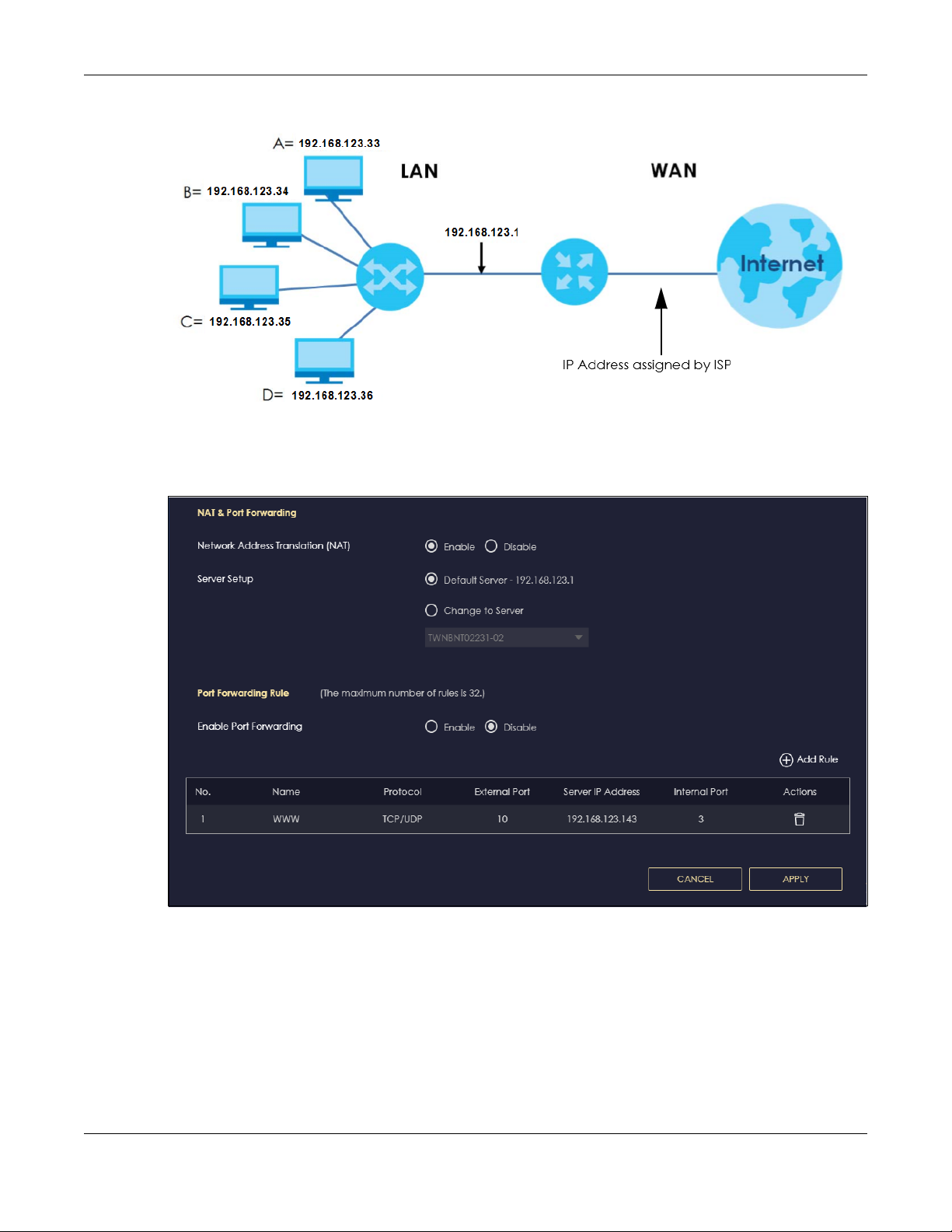
Chapter 9 WAN
Figure 45 Multiple Servers Behind NAT Example
Use this screen to enable NAT, set a default server and view the summary table of your NBG6818’s port
forwarding settings. Click Settings > Internet > NAT & Port Forwarding to show the following screen.
Figure 46 Settings > Internet > NAT & Port Forwarding
NBG6818 User’s Guide
88

Chapter 9 WAN
The following table describes the labels in this screen.
Table 25 Expert Mode > WAN > NAT > General
LABEL DESCRIPTION
NAT & Port Forwarding
Network Address
Translation (NAT)
Server Setup
Default Server You can decide whether you want to use the default server or specify a server manually. In
Change To Server Select this and manually enter the server’s IP address.
Port Forwarding Rule
Enable Port
Forwarding
No. This number uniquely identifies the port forwarding rule.
Name This field displays a name to identify this rule.
Protocol This is the transport layer protocol used for the service.
External Port This is the port number used to connect to this service using the router's external IP address on
Server IP Address This field displays the internal IP address of the server.
Internal Port This is the port number used to connect to this service using the server's internal IP address on
Actions Click the icons under Actions to delete or edit a port forwarding rule.
Apply Click Apply to save your changes back to the NBG6818.
Cancel Click Cancel to begin configuring this screen afresh.
Network Address Translation (NAT) allows the translation of an Internet protocol address used
within one network (for example a private IP address used in a local network) to a different IP
address known within another network (for example a public IP address used on the
Internet).
Select Enable to activate NAT. Select Disable to turn it off.
addition to the servers for specified services, NAT supports a default server. A default server
receives packets from ports that are not specified in the port forwarding summary table
below.
Select this to use the default server.
Select Enable to allow port forwarding. Otherwise, select Disable.
the WAN.
the LAN.
Click to delete the rule.
Click to edit the rule.
9.5.1 Add Port Forwarding Rule Screen
Use this screen to configure your NBG6818’s port forwarding settings to forward incoming service
requests to the servers on your local network. Click Settings > Internet > NAT & Port Forwarding> Add Rule
to show the following screen.
NBG6818 User’s Guide
89
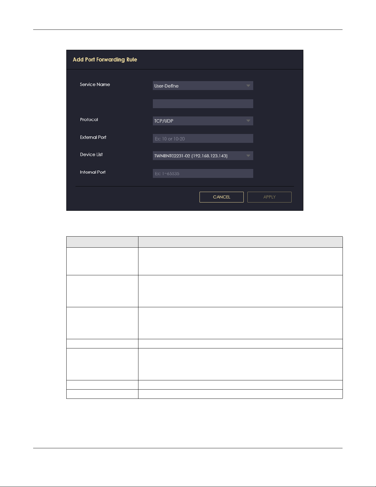
Figure 47 Add Port Forwarding Rule
Chapter 9 WAN
The following table describes the labels in this screen.
Table 26 Add Port Forwarding Rule
LABEL DESCRIPTION
Service Name Select a pre-defined service from the drop-down list box. The pre-defined service
Protocol Select the transport layer protocol supported by this virtual server. Choices are TCP,
External Port This shows the port number used to connect to this service using the router's external
Device List Select the internal IP address of the virtual server.
Internal Port This shows the port number used to connect to this service using the server's internal
Apply Click Apply to save your changes.
Cancel Click Cancel to exist this screen without saving.
port number(s) and protocol will be displayed in the port forwarding summary table.
Otherwise, select User-Define to manually enter the port number/range and select
the Protocol.
UDP, or TCP_UDP.
If you have chosen a pre-defined service in the Service Name field, the protocol will
be configured automatically.
IP address on the WAN.
If you select User-Define in the Service Name field, enter the port number(s)
manually.
IP address on the LAN.
If you select User-Define in the Service Name field, enter an internal port number
manually or leave the field blank for port range forwarding.
NBG6818 User’s Guide
90

9.6 Passthrough Screen
Use this screen to change your NBG6818’s ALGs and VPN pass-through settings. Click Settings > Internet
> Passthrough to show the following screen.
ALG Overview
Application Layer Gateway (ALG) allows the following applications to operate properly through the
NBG6818’s NAT.
• SIP - Session Initiation Protocol (SIP) - An application-layer protocol that can be used to create voice
and multimedia sessions over Internet.
• H.323 - A teleconferencing protocol suite that provides audio, data and video conferencing.
• FTP - File Transfer Protocol - an Internet file transfer service.
• SNMP - Simple Network Management Protocol - An application-layer protocol that can be used to
exchange management information between network devices.
• RTSP - Real Time Streaming Protocol - An application-layer protocol that can be used to stop, pause
or play video and audio applications streaming on the Internet.
• IRC - Internet Relay Chat - An application-layer protocol that can control the relay chat applications
and allow clients to have real-time communications with others on the Internet.
Chapter 9 WAN
The ALG feature is only needed for traffic that goes through the NBG6818’s NAT.
Figure 48 Settings > Internet > Passthrough
NBG6818 User’s Guide
91

Chapter 9 WAN
The following table describes the labels in this screen.
Table 27 Settings > Internet > Passthrough
LABEL DESCRIPTION
ALG Setup
FTP Select Enable to allow TCP packets with a specified port destination to pass through.
H.323 Select Enable to allow peer-to-peer H.323 calls.
SIP Select Enable to make sure SIP (VoIP) works correctly with port-forwarding and address-
SNMP Select Enable to allow a manager station to manage and monitor the NBG6818 through the
RTSP Select Enable to have the NBG6818 detect RTSP traffic and help build RTSP sessions through
IRC Select Enable to allow clients to have real-time communications with others on the Internet.
VPN Passthrough
PPTP Select Enable to allow VPN clients to make outbound PPTP connections. It is required in order
L2TP Select Enable to allow VPN clients to make outbound L2TP connections. It is required in order
IPSEC Select Enable to allow VPN clients to make outbound IPSec connections. It is required in
Apply Click Apply to save your changes back to the NBG6818.
Cancel Click Cancel to begin configuring this screen afresh.
mapping rules.
network via SNMP.
its NAT.
to connect to a PPTP VPN account. If PPTP is disabled, then when a client sends a request to
a VPN server, the server will reply to the NBG6818 and the NBG6818 will drop the request.
When PPTP is enabled, the NBG6818 will forward the reply from the VPN server to the client
that initiated the request, and the connection will establish successfully.
to connect to a L2TP VPN account. If L2TP is disabled, then when a client sends a request to a
VPN server, the server will reply to the NBG6818 and the NBG6818 will drop the request. When
L2TP is enabled, the NBG6818 will forward the reply from the VPN server to the client that
initiated the request, and the connection will establish successfully.
order to connect to a IPSec VPN account. If IPSEC is disabled, then when a client sends a
request to a VPN server, the server will reply to the NBG6818 and the NBG6818 will drop the
request. When IPSEC is enabled, the NBG6818 will forward the reply from the VPN server to
the client that initiated the request, and the connection will establish successfully.
9.7 Port Trigger Screen
Some services use a dedicated range of ports on the client side and a dedicated range of ports on the
server side. With regular port forwarding, you set a forwarding port in NAT to forward a service (coming
in from the server on the WAN) to the IP address of a computer on the client side (LAN). The problem is
that port forwarding only forwards a service to a single LAN IP address. In order to use the same service
on a different LAN computer, you have to manually replace the LAN computer's IP address in the
forwarding port with another LAN computer's IP address.
Trigger port forwarding addresses this problem. Trigger port forwarding allows computers on the LAN to
dynamically take turns using the service. The Zyxel Device records the IP address of a LAN computer that
sends traffic to the WAN to request a service with a specific port number and protocol (a "trigger" port).
When the Zyxel Device's WAN port receives a response with a specific port number and protocol
("open" port), the Zyxel Device forwards the traffic to the LAN IP address of the computer that sent the
request. After that computer’s connection for that service closes, another computer on the LAN can use
the service in the same manner. This way you do not need to configure a new IP address each time you
want a different LAN computer to use the application.
NBG6818 User’s Guide
92
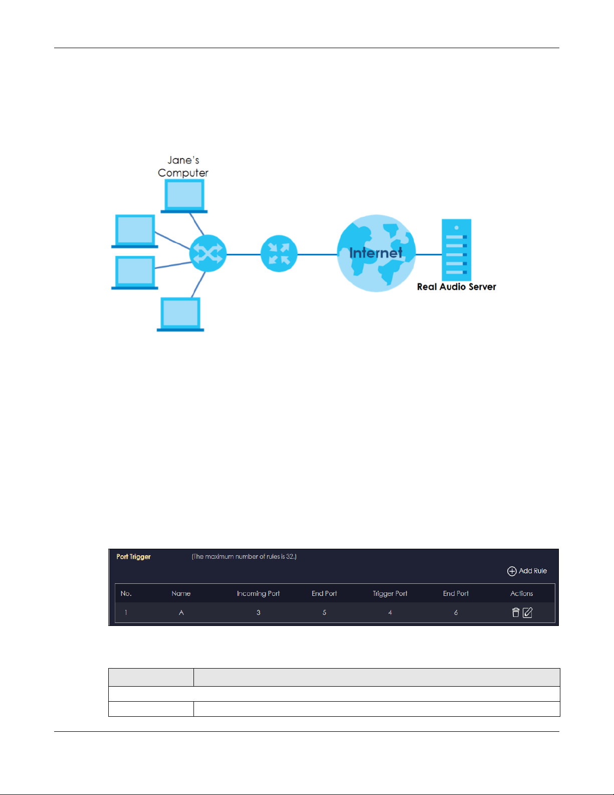
Chapter 9 WAN
Note: TCP port 7547 is reserved for system use.
Note: The maximum number of trigger ports for a single rule or all rules is 999.
Note: The maximum number of open ports for a single rule or all rules is 999.
Figure 49 Trigger Port Forwarding Process: Example
1 Jane requests a file from the Real Audio server (port 7070).
2 Port 7070 is a “trigger” port and causes the Zyxel Device to record Jane’s computer IP address. The Zyxel
Device associates Jane's computer IP address with the "open" port range of 6970-7170.
3 The Real Audio server responds using a port number ranging between 6970-7170.
4 The Zyxel Device forwards the traffic to Jane’s computer IP address.Only Jane can connect to the Real
Audio server until the connection is closed or times out. The Zyxel Device times out in three minutes with
UDP (User Datagram Protocol) or two hours with TCP/IP (Transfer Control Protocol/Internet Protocol).
Use this screen to view the summary table of your NBG6818’s port trigger settings. Click Expert Mode >
WAN > NAT > Port Trigger to show the following screen.
Note: Only one LAN computer can use a trigger port (range) at a time.
Figure 50 Expert Mode > WAN > NAT > Port Trigger
The following table describes the labels in this screen.
Table 28 Expert Mode > WAN > NAT > Port Trigger
LABEL DESCRIPTION
Port Trigger Rules (Max Limit: 32)
No. This is the rule index number.
NBG6818 User’s Guide
93
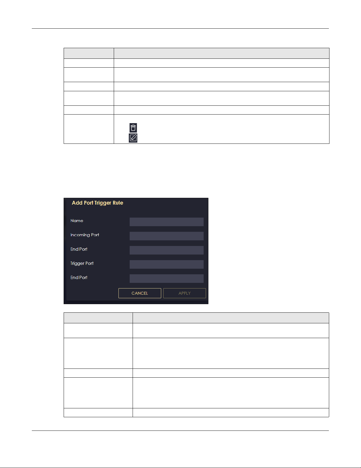
Chapter 9 WAN
Table 28 Expert Mode > WAN > NAT > Port Trigger (continued)
LABEL DESCRIPTION
Name This field displays a name to identify this rule.
Incoming Port This field displays a port number that a server on the WAN uses when it sends out a particular
service.
End Port This field displays a port number or the final port number in a range of port numbers.
Trigger Port This field displays a port number that causes the NBG6818 to record the IP address of the LAN
computer that sent then traffic to a server on the WAN.
End Port This field displays a port number or the ending port number in a range of port numbers.
Actions Click the icons under Actions to delete or edit an existing trigger port settings.
Click to delete the rule.
Click to edit the rule.
9.7.1 Add Port Trigger Rule Screen
Use this screen to configure your NBG6818’s port trigger settings. Click Expert Mode > WAN > NAT > Port
Trigger > Add Rule to show the following screen.
Figure 51 Add Port Trigger Rule
Table 29 Add Port Trigger Rule
LABEL DESCRIPTION
Name Type a unique name (up to 15 characters) for identification purposes. All characters
are permitted - including spaces.
Incoming Port Incoming is a port (or a range of ports) that a server on the WAN uses when it sends
End Port Type a port number or the ending port number in a range of port numbers.
Trigger Port The trigger port is a port (or a range of ports) that causes (or triggers) the ARMOR Z1
End Port Type a port number or the ending port number in a range of port numbers.
out a particular service. The ARMOR Z1 forwards the traffic with this port (or range of
ports) to the client computer on the LAN that requested the service.
Type a port number or the starting port number in a range of port numbers.
to record the IP address of the LAN computer that sent the traffic to a server on the
WAN.
Type a port number or the starting port number in a range of port numbers.
NBG6818 User’s Guide
94
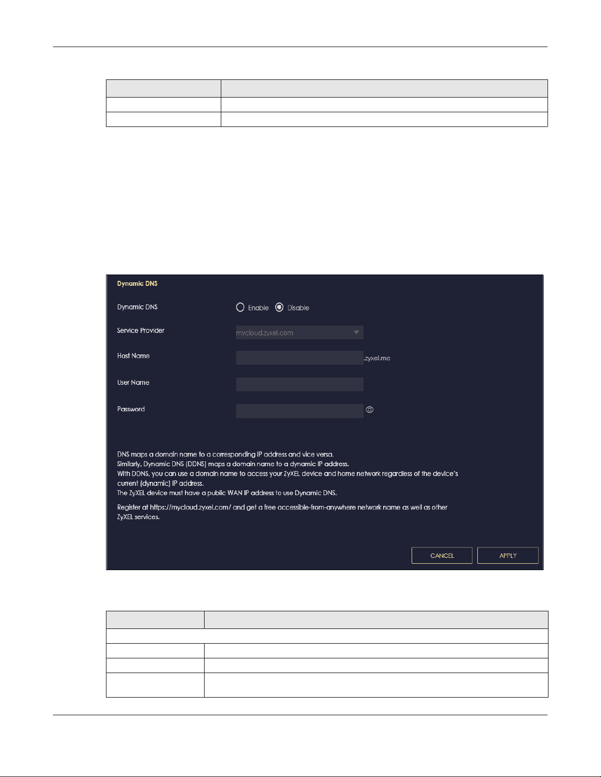
Table 29 Add Port Trigger Rule
LABEL DESCRIPTION
Apply Click Apply to save your changes.
Cancel Click Cancel to exist this screen without saving.
9.8 Dynamic DNS Screen
Use this screen to change your NBG6818’s DDNS settings. Click Settings > Internet > Dynamic DNS to
show the following screen.
Note: You can register at https://mycloud.zyxel.com/ to get a free accessible-from-anywhere
DDNS account.
Figure 52 Settings> Internet > Dynamic DNS
Chapter 9 WAN
The following table describes the labels in this screen.
Table 30 Settings > Internet > Dynamic DNS
LABEL DESCRIPTION
Dynamic DNS Setup
Dynamic DNS Select Enable to use dynamic DNS. Select Disable to turn this feature off.
Service Provider Select the name of your Dynamic DNS service provider.
Host Name Enter a host names in the field provided. You can specify up to two host names in the
field separated by a comma (",").
NBG6818 User’s Guide
95

Table 30 Settings > Internet > Dynamic DNS (continued)
LABEL DESCRIPTION
Username Enter your user name.
Password Enter the password assigned to you.
Apply Click Apply to save your changes back to the NBG6818.
Cancel Click Cancel to begin configuring this screen afresh.
9.9 UPnP Screen
Universal Plug and Play (UPnP) is a distributed, open networking standard that uses TCP/IP for simple
peer-to-peer network connectivity between devices. A UPnP device can dynamically join a network,
obtain an IP address, convey its capabilities, and learn about other devices on the network. A device
can then leave a network smoothly and automatically when it is no longer in use.
See Section 9.9.1 on page 97 and Section 9.9.2 on page 99 for more information on UPnP.
Use this screen to enable UPnP on your NBG6818. Click Settings > Internet > UPnP to display the following
screen.
Chapter 9 WAN
Figure 53 Settings > Internet > UPnP
Table 31 Settings > Internet > UPnP
LABEL DESCRIPTION
UPnP Setup
Enable UPnP Select Enable to activate UPnP.
Be aware that anyone could use a UPnP application to open the web configurator's
login screen without entering the NBG6818's IP address (although you must still enter
the password to access the web configurator).
UPnP Setup Rule
No. This is the number of an individual UPnP entry.
Protocol This is the transport layer protocol used for the service.
InPort InPort is a port that a LAN computer uses when it requests a particular service. This
port is only applicable to the local network.
This field displays the port number of the UPnP entry.
OutPort OutPort is the well-known port that the WAN server uses to reply to the LAN computer
that made the request using In Port.
This field displays the port number of the UPnP entry.
NBG6818 User’s Guide
96

Chapter 9 WAN
Table 31 Settings > Internet > UPnP
LABEL DESCRIPTION
IP Address This field displays the IP address of this UPnP entry.
Apply Click Apply to save your settings.
Cancel Click Cancel to return to the previously saved settings.
9.9.1 Turning On UPnP in Windows 7 Example
This section shows you how to use the UPnP feature in Windows 7. UPnP server is installed in Windows 7.
Activate UPnP on the NBG6818 in Settings > Internet > UPnP.
Make sure the computer is connected to a LAN port of the NBG6818. Turn on your computer and the
NBG6818.
1 Click the start icon, Control Panel and then the Network and Sharing Center.
2 Click Change Advanced Sharing Settings.
NBG6818 User’s Guide
97

Chapter 9 WAN
3 Select Turn on network discovery and click Save Changes. Network discovery allows your computer to
find other computers and devices on the network and other computers on the network to find your
computer. This makes it easier to share files and printers.
NBG6818 User’s Guide
98

Chapter 9 WAN
9.9.2 Turning on UPnP in Windows 10 Example
This section shows you how to use the UPnP feature in Windows 10. UPnP server is installed in Windows 10.
Activate UPnP on the NBG6818 in Settings > Internet > UPnP.
Make sure the computer is connected to the LAN port of the NBG6818. Turn on your computer and the
NBG6818.
1 Click the start icon, Settings and then Network & Internet.
NBG6818 User’s Guide
99

Chapter 9 WAN
2 Click Network and Sharing Center.
3 Click Change advanced sharing settings.
NBG6818 User’s Guide
100
 Loading...