


CHAPTER 19
Management
19.1 Overview
This chapter explains how to configure TR-069 and remote management on the
NVG2053.
19.1.1 What You Can Do in this Chapter
•Use the TR-069 screen (Section 19.5 on page 204) to configure the NVG2053’s
TR-069 auto-configuration settings.
•Use the WWW screen (Section 19.5 on page 204) to configure the NVG2053’s
HTTP management settings.
•Use the Telnet screen (Section 19.5 on page 204) to specify which interfaces
allow Telnet access and from which IP address the access can come.
•Use the ICMP screen (Section 19.6 on page 205) to specify which of the
NVG2053’s interfaces will respond to Ping requests.
19.2 What You Need To Know
Firewall Rules
When you configure remote management to allow management from any network
except the LAN, you still need to configure a firewall rule to allow access. See
Chapter 13 on page 251 for details on configuring firewall rules.
You can also disable a service on the NVG2053 by not allowing access for the
service/protocol through any of the NVG2053 interfaces.
Remote Management Sessions
You may only have one remote management session running at a time. The
NVG2053 automatically disconnects a remote management session of lower
priority when another remote management session of higher priority starts. The
priorities for the different types of remote management sessions are as follows.
NVG2053 User’s Guide
201

Chapter 19 Management
1 Tel ne t
2 HTTP
Remote Management Limitations
Remote management does not work when:
1 You have not enabled that service on the interface in the corresponding remote
management screen.
2 You have disabled that service in one of the remote management screens.
3 The IP address in the Secured Client IP Address field does not match the client
IP address. If it does not match, the NVG2053 will disconnect the session
immediately.
4 There is already another remote management session with an equal or higher
priority running. You may only have one remote management session running at
one time.
5 There is a firewall rule that blocks it.
System Timeout
There is a default system management idle timeout of five minutes (three
hundred seconds). The NVG2053 automatically logs you out if the management
session remains idle for longer than this timeout period. The management session
does not time out when a statistics screen is polling. You can change the timeout
period in the Maintenance > General screen.
19.3 The TR-069 Screen
TR-069 defines how Customer Premise Equipment (CPE), for example your
NVG2053, can be managed over the WAN by an Auto Configuration Server (ACS).
TR-069 is based on sending Remote Procedure Calls (RPCs) between an ACS and a
client device. RPCs are sent in Extensible Markup Language (XML) format over
HTTP or HTTPS.
An administrator can use an ACS to remotely set up the NVG2053, modify
settings, perform firmware upgrades as well as monitor and diagnose the
NVG2053. You have to enable the device to be managed by the ACS and specify
the ACS IP address or domain name and username and password.
202
NVG2053 User’s Guide
Chapter 19 Management
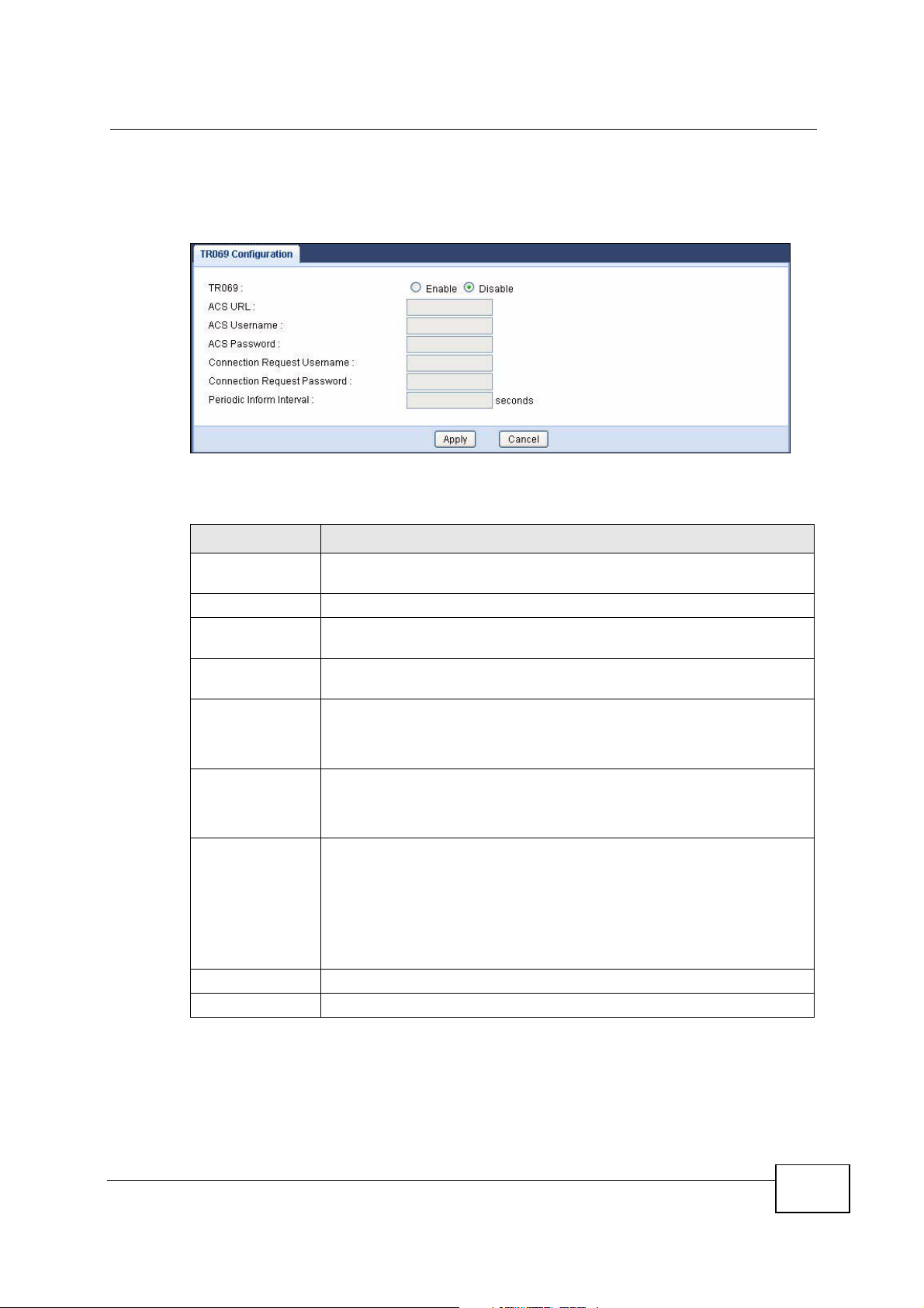
Click Configuration > Management > TR-069 to open the following screen.
Use this screen to configure your NVG2053 to be managed by an ACS.
Figure 87 Management > TR-069
The following table describes the fields in this screen.
Table 69 Management > TR-069
LABEL DESCRIPTION
TR069 Select Enable to activate remote management via TR-069 on the
WAN. Otherwise, select Disable.
ACS URL Enter the URL or IP address of the auto-configuration server.
ACS Username Enter the TR-069 user name for authentication with the auto-
configuration server.
ACS Password Enter the TR-069 password for authentication with the auto-
configuration server.
Connection
Request
Username
Connection
Request
Password
Periodic Inform
Interval
Enter the connection request user name.
When the ACS makes a connection request to the NVG2053, this user
name is used to authenticate the ACS.
Enter the connection request password.
When the ACS makes a connection request to the NVG2053, this
password is used to authenticate the ACS.
The NVG2053 can initiate a connection to the ACS using the preconfigured address at any time.
Apply Click Apply to save your changes back to the NVG2053.
Cancel Click Cancel to begin configuring this screen afresh.
NVG2053 User’s Guide
Enter the time interval (in seconds) at which the NVG2053 sends
information to the auto-configuration server.
“0” means the NVG2053 will not establish periodic communication with
the ACS.
203
Chapter 19 Management
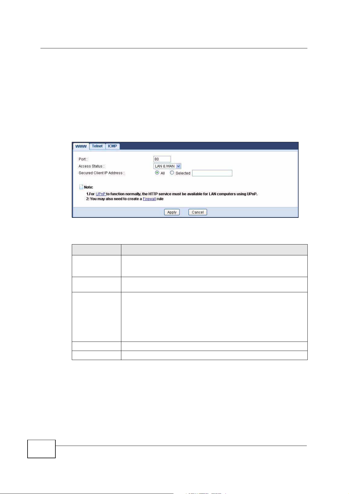
19.4 The WWW Screen
Use this screen to configure the NVG2053’s HTTP management settings.
Note: If you disable the HTTP service in the WWW screen, then the NVG2053 blocks
all HTTP connection attempts.
Click Management > Remote MGMT > WWW to open the following screen.
Figure 88 Remote MGMT > WWW
The following table describes the fields in this screen.
Table 70 Remote MGMT > WWW
LABEL DESCRIPTION
Port You may change the server port number for a service if needed,
however you must use the same port number in order to use that
service for remote management.
Access Status Select the interface(s) through which a computer may access the
NVG2053 using this service.
Secured Client IP
Address
Apply
Cancel
A secure client is a “trusted” computer that is allowed to communicate
with the NVG2053 using this service.
Select All to allow any computer to access the NVG2053 using this
service.
Choose Selected to just allow the computer with the IP address that
you specify to access the NVG2053 using this service.
Click this to save your changes and to apply them to the NVG2053.
Click this to set every field in this screen to its last-saved value.
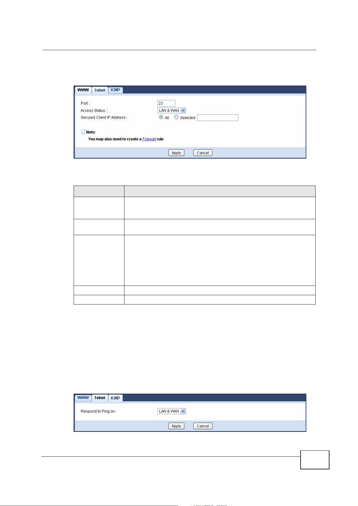
19.5 The Telnet Screen
204
Use this screen to specify which interfaces allow Telnet access and from which IP
address the access can come.
NVG2053 User’s Guide
Chapter 19 Management
Click Management > Remote MGMT > Telnet to open the following screen.
Figure 89 Remote MGMT > Telnet
The following table describes the fields in this screen.
Table 71 Remote MGMT > Telnet
LABEL DESCRIPTION
Port You may change the server port number for a service if needed,
however you must use the same port number in order to use that
service for remote management.
Access Status Select the interface(s) through which a computer may access the
NVG2053 using this service.
Secured Client IP
Address
A secure client is a “trusted” computer that is allowed to communicate
with the NVG2053 using this service.
Select All to allow any computer to access the NVG2053 using this
service.
Choose Selected to just allow the computer with the IP address that
you specify to access the NVG2053 using this service.
Apply
Cancel
Click this to save your changes and to apply them to the NVG2053.
Click this to set every field in this screen to its last-saved value.
19.6 The ICMP Screen
Use this screen to help keep the NVG2053 hidden from probing attempts. You can
specify which of the NVG2053’s interfaces will respond to Ping requests.
Click Management > Remote MGMT > ICMP to open the following screen.
Figure 90 Remote MGMT > ICMP
NVG2053 User’s Guide
205

Chapter 19 Management
The following table describes the fields in this screen.
Table 72 Remote MGMT > ICMP
LABEL DESCRIPTION
Respond to Ping onSelect the interface(s) that you want to reply to incoming Ping
Apply
Cancel
requests.
Select Disable to have the NVG2053 not respond to any Ping requests
that come into an interface.
Click this to save your changes and to apply them to the NVG2053.
Click this to set every field in this screen to its last-saved value.
206
NVG2053 User’s Guide
CHAPTER 20
Maintenance
20.1 Overview
This chapter provides information on the Maintenance > General screen.
20.2 What You Can Do
Use the General screen (Section 20.3 on page 207) to enter a name to identify
the NVG2053 in the network, and configure your device’s domain name and
management inactivity timeout.
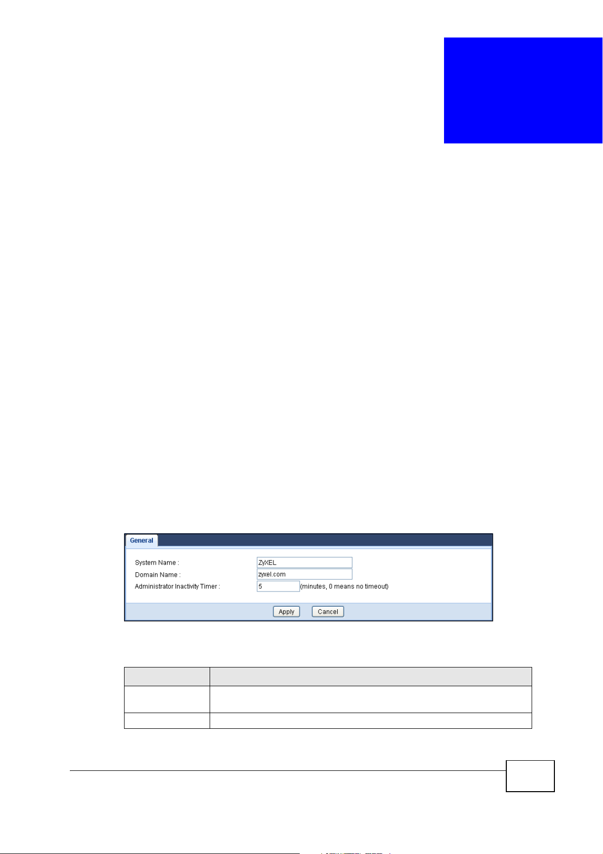
20.3 General Screen
Use this screen to enter a name to identify the NVG2053 in the network and set
the management inactivity timeout. Click Maintenance > General. The following
screen displays.
Figure 91 Maintenance > General
The following table describes the labels in this screen.
Table 73 Maintenance > General
LABEL DESCRIPTION
System Name System Name is a unique name to identify the NVG2053 in an
Ethernet network.
Domain Name Enter the domain name you want to give to the NVG2053.
NVG2053 User’s Guide
207

Chapter 20 Maintenance
Table 73 Maintenance > General
LABEL DESCRIPTION
Administrator
Inactivity Timer
Apply Click Apply to save your changes back to the NVG2053.
Cancel Click Cancel to begin configuring this screen afresh.
Type how many minutes a management session can be left idle before
the session times out. The default is 5 minutes. After it times out you
have to log in with your password again. Very long idle timeouts may
have security risks. A value of "0" means a management session never
times out, no matter how long it has been left idle (not
recommended).
208
NVG2053 User’s Guide
CHAPTER 21
Password
21.1 Overview
This chapter contains information about configuring the Maintenance >
Password screen.
21.1.1 What You Can Do in this Chapter
Use the Password screen (Section 21.2 on page 209) to configure the system
password.
21.2 Password Screen
Use the Password screen to change your NVG2053’s password (recommended).
Click Maintenance > Password.
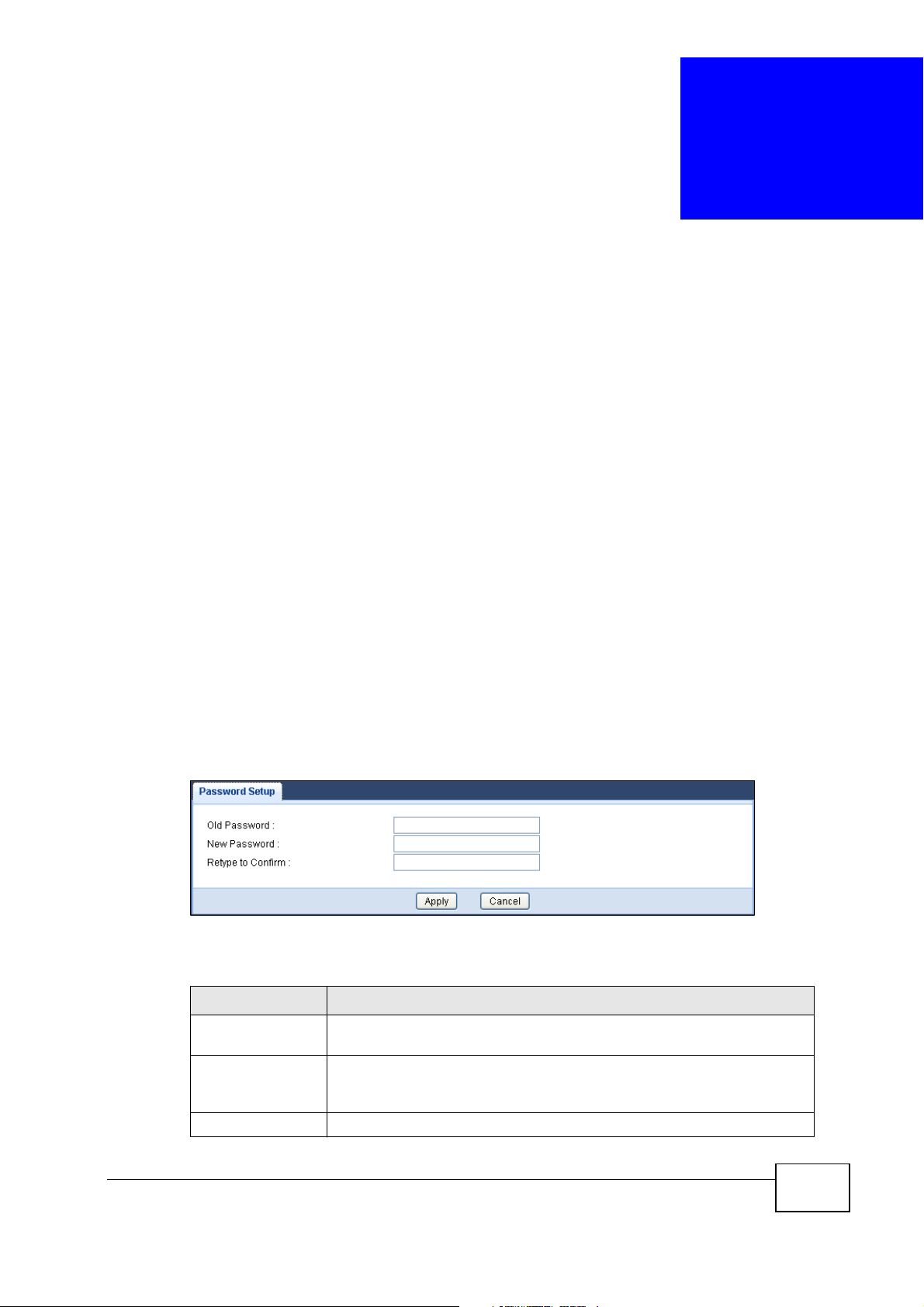
Figure 92 Maintenance > Password
The following table describes the labels in this screen.
Table 74 Maintenance > Password
LABEL DESCRIPTION
Old Password Type the default password or the existing password you use to access
the system in this field.
New Password Type your new system password (up to 30 characters). Note that as
you type a password, the screen displays an asterisk (*) for each
character you type.
Retype to Confirm Type the new password again in this field.
NVG2053 User’s Guide
209

Chapter 21 Password
Table 74 Maintenance > Password
LABEL DESCRIPTION
Apply Click Apply to save your changes back to the NVG2053.
Cancel Click Cancel to begin configuring this screen afresh.
210
NVG2053 User’s Guide

CHAPTER 22
Time
22.1 Overview
This chapter provides information on the Time screen.
22.1.1 What You Can Do in this Chapter
Use the Time Setting screen (Section 22.2 on page 212) to change your
NVG2053’s time and date.
NVG2053 User’s Guide
211
Chapter 22 Time
22.2 Time Setting Screen
Use this screen to configure the NVG2053’s time based on your local time zone. To
change your NVG2053’s time and date, click Maintenance > Time. The screen
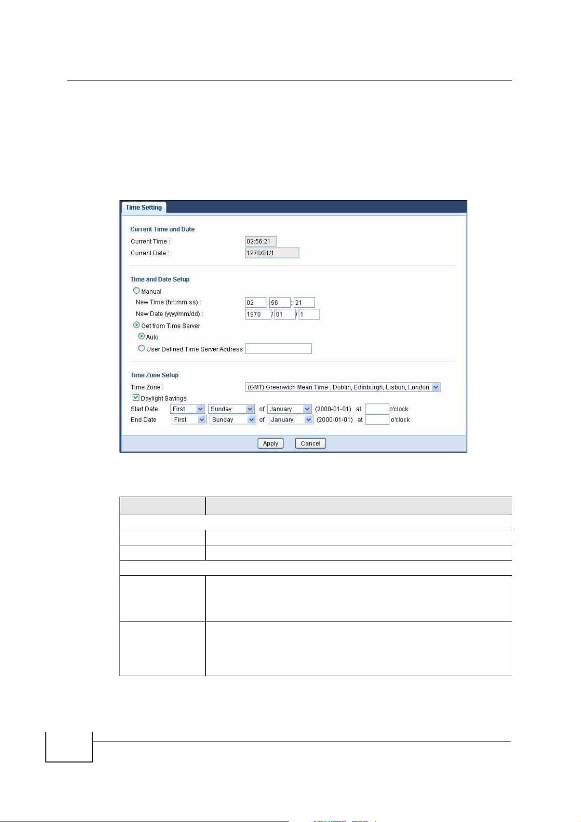
appears as shown.
Figure 93 Maintenance > Time
212
he following table describes the labels in this screen.
Table 75 Maintenance > Time
LABEL DESCRIPTION
Current Time and Date
Current Time This field displays the time of your NVG2053.
Current Date This field displays the date of your NVG2053.
Time and Date Setup
Manual Select this radio button to enter the time and date manually. If you
configure a new time and date, Time Zone and Daylight Saving at the
same time, the new time and date you entered has priority and the
Time Zone and Daylight Saving settings do not affect it.
New Time
(hh:mm:ss)
This field displays the last updated time from the time server or the
last time configured manually.
When you set Time and Date Setup to Manual, enter the new time
in this field and then click Apply.
NVG2053 User’s Guide
Chapter 22 Time
Table 75 Maintenance > Time
LABEL DESCRIPTION
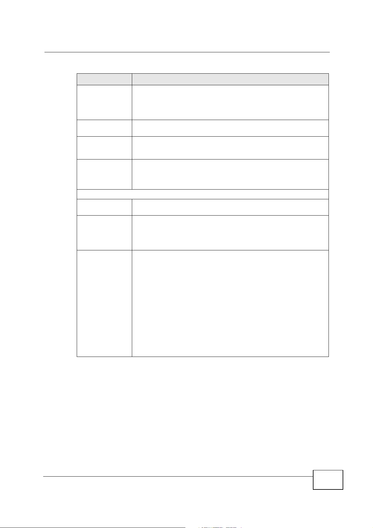
New Date
(yyyy/mm/dd)
Get from Time
Server
Auto Select Auto to have the NVG2053 automatically search for an
User Defined
Time Server
Address
Time Zone Setup
Time Zone Choose the time zone of your location. This will set the time
Daylight Savings Daylight saving is a period from late spring to fall when many
This field displays the last updated date from the time server or the
last date configured manually.
When you set Time and Date Setup to Manual, enter the new date
in this field and then click Apply.
Select this radio button to have the NVG2053 get the time and date
from the time server you specified below.
available time server and synchronize the date and time with the time
server after you click Apply.
Select User Defined Time Server Address and enter the IP
address or URL (up to 20 extended ASCII characters in length) of
your time server. Check with your ISP/network administrator if you
are unsure of this information.
difference between your time zone and Greenwich Mean Time (GMT).
countries set their clocks ahead of normal local time by one hour to
give more daytime light in the evening.
Select this option if you use Daylight Saving Time.
Start Date Configure the day and time when Daylight Saving Time starts if you
selected Daylight Savings. The o'clock field uses the 24 hour
format. Here are a couple of examples:
Daylight Saving Time starts in most parts of the United States on the
first Sunday of April. Each time zone in the United States starts using
Daylight Saving Time at 2 A.M. local time. So in the United States you
would select First, Sunday, April and type 2 in the o'clock field.
Daylight Saving Time starts in the European Union on the last Sunday
of March. All of the time zones in the European Union start using
Daylight Saving Time at the same moment (1 A.M. GMT or UTC). So
in the European Union you would select Last, Sunday, March. The
time you type in the o'clock field depends on your time zone. In
Germany for instance, you would type 2 because Germany's time
zone is one hour ahead of GMT or UTC (GMT+1).
NVG2053 User’s Guide
213
Chapter 22 Time
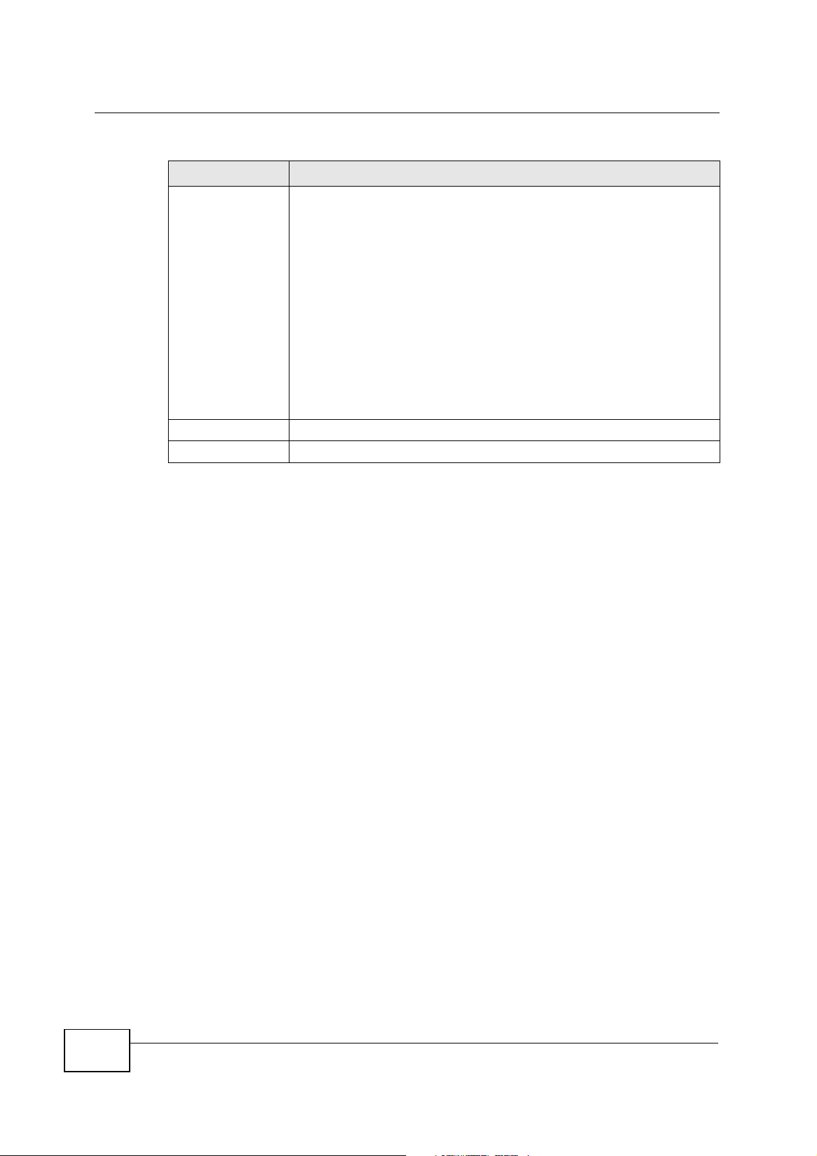
Table 75 Maintenance > Time
LABEL DESCRIPTION
End Date Configure the day and time when Daylight Saving Time ends if you
Apply Click Apply to save your changes back to the NVG2053.
Cancel Click Cancel to begin configuring this screen afresh.
selected Daylight Savings. The o'clock field uses the 24 hour
format. Here are a couple of examples:
Daylight Saving Time ends in the United States on the last Sunday of
October. Each time zone in the United States stops using Daylight
Saving Time at 2 A.M. local time. So in the United States you would
select Last, Sunday, October and type 2 in the o'clock field.
Daylight Saving Time ends in the European Union on the last Sunday
of October. All of the time zones in the European Union stop using
Daylight Saving Time at the same moment (1 A.M. GMT or UTC). So
in the European Union you would select Last, Sunday, October. The
time you type in the o'clock field depends on your time zone. In
Germany for instance, you would type 2 because Germany's time
zone is one hour ahead of GMT or UTC (GMT+1).
214
NVG2053 User’s Guide
CHAPTER 23
Firmware Upgrade
23.1 Overview
This chapter shows you how to upload a new firmware.
23.1.1 What You Can Do in this Chapter
Use the Firmware Upgrade screen (Section 23.2 on page 215) to upload
firmware to your NVG2053.
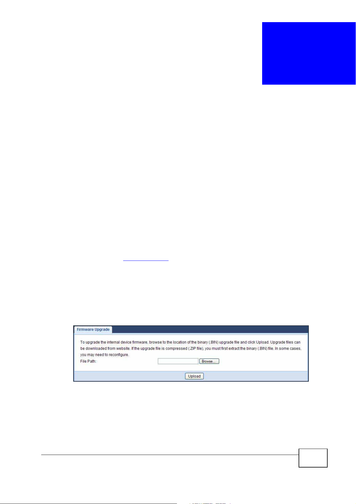
23.2 Firmware Upgrade Screen
Find firmware at www.zyxel.com in a file that (usually) uses the system model
name with a “*.bin” extension, e.g., “NVG2053.bin”. The upload process uses
HTTP (Hypertext Transfer Protocol) and may take up to two minutes. After a
successful upload, the system will reboot.
Click Maintenance > Firmware Upgrade. Follow the instructions in this screen
to upload firmware to your NVG2053.
Figure 94 Maintenance > Firmware Upgrade
NVG2053 User’s Guide
215
Chapter 23 Firmware Upgrade
The following table describes the labels in this screen.
Table 76 Maintenance > Firmware Upgrade
LABEL DESCRIPTION
File Path Type in the location of the file you want to upload in this field or click
Browse... Click Browse... to find the .bin file you want to upload. Remember that
Upload Click Upload to begin the upload process. This process may take up to
Note: Do not turn off the NVG2053 while firmware upload is in progress!
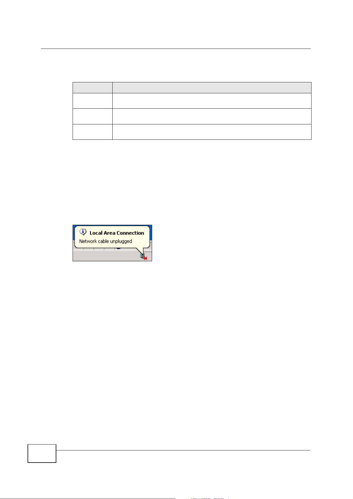
After you see the Firmware Upgrade is proceeding screen, wait six minutes
before logging into the NVG2053 again.
The NVG2053 automatically restarts in this time causing a temporary network
disconnect. In some operating systems, you may see the following icon on your
desktop.
Browse... to find it.
you must decompress compressed (.zip) files before you can upload them.
two minutes.
Figure 95 Network Temporarily Disconnected
After six minutes, log in again and check your new firmware version in the Status
screen.
If the upload was not successful, an error message appears. Click OK to go back
to the Firmware screen.
216
NVG2053 User’s Guide

CHAPTER 24
Backup/Restore
24.1 Overview
This chapter shows you how to backup, restore and reset your NVG2053.
Backup configuration allows you to back up (save) the NVG2053’s current
configuration to a file on your computer. Once your NVG2053 is configured and
functioning properly, it is highly recommended that you back up your configuration
file before making configuration changes. The backup configuration file will be
useful in case you need to return to your previous settings.
Restore configuration allows you to upload a new or previously saved
configuration file from your computer to your NVG2053.
24.1.1 What You Can Do in this Chapter
Use the Backup/Restore screen (Section 24.2 on page 218) to view information
related to factory defaults, backup configuration, and restoring configuration.
NVG2053 User’s Guide
217
Chapter 24 Backup/Restore
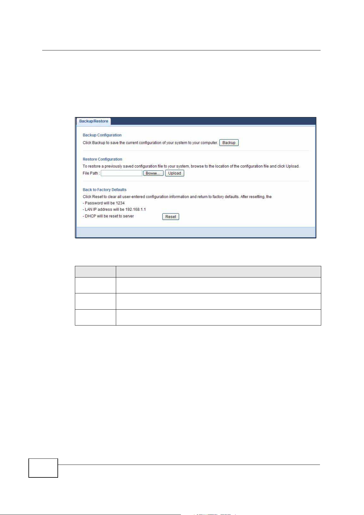
24.2 Backup/Restore Screen
Click Maintenance > Backup/Restore. Information related to factory defaults,
backup configuration, and restoring configuration appears as shown next.
Figure 96 Maintenance > Backup/Restore
The following table describes the labels in this screen.
Table 77 Maintenance > Backup/Restore
LABEL DESCRIPTION
Backup Click Backup to save the NVG2053’s current configuration to your
computer.
File Path Type in the location of the file you want to upload in this field or click
Browse... to find it.
Browse... Click Browse... to find the file you want to upload. Remember that you
must decompress compressed (.ZIP) files before you can upload them.
218
NVG2053 User’s Guide
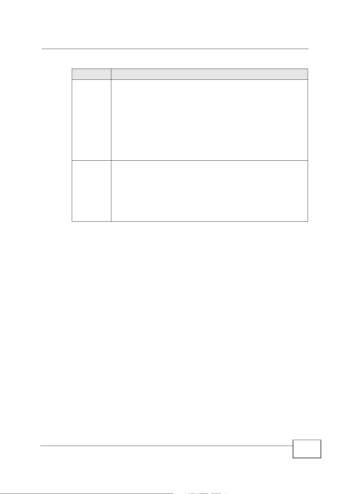
Table 77 Maintenance > Backup/Restore
LABEL DESCRIPTION
Upload Click Upload to begin the upload process.
Note: Do not turn off the NVG2053 while configuration file upload is in
progress.
After you see a “configuration upload successful” screen, you must then
wait one minute before logging into the NVG2053 again. The NVG2053
automatically restarts in this time causing a temporary network
disconnect.
If you see an error screen, click OK to return to the Backup/Restore
screen.
Reset
Pressing the Reset button in this section clears all user-entered
configuration information and returns the NVG2053 to its factory
defaults.
You can also press the RESET button on the side panel to reset the
factory defaults of your NVG2053. Refer to the chapter about
introducing the Web Configurator for more information on the
RESET button.
Chapter 24 Backup/Restore
Note: If you uploaded the default configuration file you may need to change the IP
address of your computer to be in the same subnet as that of the default
NVG2053 IP address (192.168.1.1). See Appendix B on page 247 for details on
how to set up your computer’s IP address.
NVG2053 User’s Guide
219

Chapter 24 Backup/Restore
220
NVG2053 User’s Guide
CHAPTER 25
Language
25.1 Overview
This chapter shows you how to change the Web Configurator’s display language.
25.2 What You Can Do
Use the Language screen (Section 25.3 on page 221) to change the language for
the Web Configurator display.
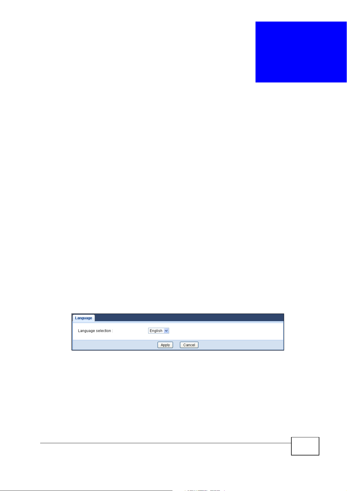
25.3 The Language Screen
Select the language you prefer and click Apply. The Web Configurator language
changes after a while without restarting the NVG2053. Click Maintenance >
Language.
At the time of writing, the NVG2053 supports English only.
Figure 97 Language
NVG2053 User’s Guide
221

Chapter 25 Language
222
NVG2053 User’s Guide
CHAPTER 26
Restart
26.1 Overview
This chapter shows you how to restart your NVG2053.
26.2 What You Can Do
Use the Restart screen (Section 26.3 on page 223) to reboot the NVG2053
without turning the power off.
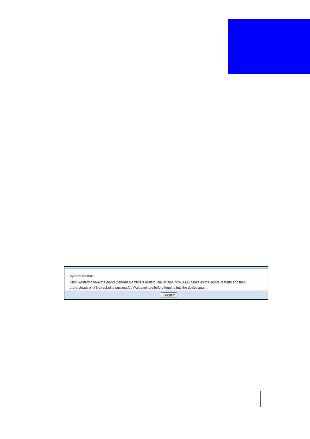
26.3 The Restart Screen
System restart allows you to reboot the NVG2053 without turning the power off.
Click Maintenance > Restart to open the following screen.
Figure 98 Maintenance > Restart
Click Restart to have the NVG2053 reboot. This does not affect the NVG2053's
configuration.
NVG2053 User’s Guide
223

Chapter 26 Restart
224
NVG2053 User’s Guide

CHAPTER 27
Troubleshooting
This chapter offers some suggestions to solve problems you might encounter. The
potential problems are divided into the following categories.
• Power, Hardware Connections, and LEDs
• NVG2053 Access and Login
• Internet Access
• Resetting the NVG2053 to Its Factory Defaults
• Wireless Router/AP Troubleshooting
27.1 Power, Hardware Connections, and LEDs
The NVG2053 does not turn on. None of the LEDs turn on.
1 Make sure you are using the power adaptor or cord included with the NVG2053.
2 Make sure the power adaptor or cord is connected to the NVG2053 and plugged in
to an appropriate power source. Make sure the power source is turned on.
3 Disconnect and re-connect the power adaptor or cord to the NVG2053.
4 If the problem continues, contact the vendor.
One of the LEDs does not behave as expected.
1 Make sure you understand the normal behavior of the LED. See Section 1.5 on
page 24.
2 Check the hardware connections. See the Quick Start Guide.
NVG2053 User’s Guide
225

Chapter 27 Troubleshooting
3 Inspect your cables for damage. Contact the vendor to replace any damaged
cables.
4 Disconnect and re-connect the power adaptor to the NVG2053.
5 If the problem continues, contact the vendor.
27.2 NVG2053 Access and Login
I don’t know the IP address of my NVG2053.
1 The default IP address is 192.168.1.1.
2 If you changed the IP address and have forgotten it, you might get the IP address
of the NVG2053 by looking up the IP address of the default gateway for your
computer. To do this in most Windows computers, click Start > Run, enter cmd,
and then enter ipconfig. The IP address of the Default Gateway might be the IP
address of the NVG2053 (it depends on the network), so enter this IP address in
your Internet browser.
3 Reset your NVG2053 to change all settings back to their default. This means your
current settings are lost. See Section 27.4 on page 229 in the Troubleshooting
for information on resetting your NVG2053.
I forgot the password.
1 The default password is 1234.
2 If this does not work, you have to reset the device to its factory defaults. See
Section 27.4 on page 229.
I cannot see or access the Login screen in the Web Configurator.
1 Make sure you are using the correct IP address.
• The default IP address is 192.168.1.1.
226
NVG2053 User’s Guide

Chapter 27 Troubleshooting
• If you changed the IP address (Section 9.4 on page 123), use the new IP
address.
• If you changed the IP address and have forgotten it, see the troubleshooting
suggestions for I don’t know the IP address of my NVG2053.
2 Check the hardware connections, and make sure the LEDs are behaving as
expected. See the Quick Start Guide.
3 Make sure your Internet browser does not block pop-up windows and has
JavaScripts and Java enabled. See Appendix A on page 235.
4 Make sure your computer is in the same subnet as the NVG2053. (If you know
that there are routers between your computer and the NVG2053, skip this step.)
• If there is a DHCP server on your network, make sure your computer is using
a dynamic IP address. See Section 10.3 on page 126.
• If there is no DHCP server on your network, make sure your computer’s IP
address is in the same subnet as the NVG2053. See Appendix C on page 263.
5 Reset the device to its factory defaults, and try to access the NVG2053 with the
default IP address. See Section 24.2 on page 218.
6 If the problem continues, contact the network administrator or vendor, or try one
of the advanced suggestions.
Advanced Suggestion
• If your computer is connected to the WAN port or is connected wirelessly, use a
computer that is connected to a LAN/ETHERNET port.
I can see the Login screen, but I cannot log in to the NVG2053.
1 Make sure you have entered the password correctly. The default password is
1234. This field is case-sensitive, so make sure [Caps Lock] is not on.
2 This can happen when you fail to log out properly from your last session. Try
logging in again after 5 minutes (default).
3 Disconnect and re-connect the power adaptor or cord to the NVG2053.
4 If this does not work, you have to reset the device to its factory defaults. See
Section 27.4 on page 229.
NVG2053 User’s Guide
227

Chapter 27 Troubleshooting
27.3 Internet Access
I cannot access the Internet.
1 Check the hardware connections, and make sure the LEDs are behaving as
expected. See the Quick Start Guide.
2 Make sure you entered your ISP account information correctly in the wizard or
Broadband screen. These fields are case-sensitive, so make sure [Caps Lock] is
not on.
3 If you are trying to access the Internet wirelessly, make sure the wireless settings
in the wireless client are the same as the settings in the NVG2053.
4 Disconnect all the cables from your device, and follow the directions in the Quick
Start Guide again.
5 If the problem continues, contact your ISP.
I cannot access the Internet anymore. I had access to the Internet (with the
NVG2053), but my Internet connection is not available anymore.
1 Check the hardware connections, and make sure the LEDs are behaving as
expected. See the Quick Start Guide and Section 1.5 on page 24.
2 Reboot the NVG2053.
3 If the problem continues, contact your ISP.
The Internet connection is slow or intermittent.
1 There might be a lot of traffic on the network. Look at the LEDs, and check Section
1.5 on page 24. If the NVG2053 is sending or receiving a lot of information, try
closing some programs that use the Internet, especially peer-to-peer applications.
228
NVG2053 User’s Guide

Chapter 27 Troubleshooting
2 Check the signal strength. If the signal strength is low, try moving the NVG2053
closer to the AP if possible, and look around to see if there are any devices that
might be interfering with the wireless network (for example, microwaves, other
wireless networks, and so on).
3 Reboot the NVG2053.
4 If the problem continues, contact the network administrator or vendor, or try one
of the advanced suggestions.
Advanced Suggestions
• Check the settings for QoS. If it is disabled, you might consider activating it. If it
is enabled, you might consider raising or lowering the priority for some
applications.
27.4 Resetting the NVG2053 to Its Factory
Defaults
If you reset the NVG2053, you lose all of the changes you have made. The
NVG2053 re-loads its default settings, and the password resets to 1234. You have
to make all of your changes again.
You will lose all of your changes when you push the RESET button.
To reset the NVG2053,
1 Make sure the power LED is on.
2 Press the RESET button for longer than 10 seconds to set the NVG2053 back to its
factory-default configurations.
If the NVG2053 restarts automatically, wait for the NVG2053 to finish restarting,
and log in to the Web Configurator. The password is “1234”.
If the NVG2053 does not restart automatically, disconnect and reconnect the
NVG2053’s power. Then, follow the directions above again.
NVG2053 User’s Guide
229

Chapter 27 Troubleshooting
27.5 Wireless Router/AP Troubleshooting
I cannot access the NVG2053 or ping any computer from the WLAN.
1 Make sure the wireless LAN is enabled on the NVG2053
2 Make sure the wireless adapter on the wireless station is working properly.
3 Make sure the wireless adapter installed on your computer is IEEE 802.11
compatible and supports the same wireless standard as the NVG2053.
4 Make sure your computer (with a wireless adapter installed) is within the
transmission range of the NVG2053.
5 Check that both the NVG2053 and your wireless station are using the same
wireless and wireless security settings.
6 Make sure you allow the NVG2053 to be remotely accessed through the WLAN
interface. Check your remote management settings.
• See the chapter on Wireless LAN in the User’s Guide for more information.
230
NVG2053 User’s Guide

CHAPTER 28
Product Specifications
The following tables summarize the NVG2053’s hardware and firmware features.
Table 78 Hardware Features
Device Dimensions
(W x D x H)
Device Weight 395 g
Power Specification Input: 100~240 V AC, 50~60 Hz
Ethernet ports Auto-negotiating: 10 Mbps, 100 Mbps, 1000 Mbps in either half-
4-Port Switch A combination of switch and router makes your NVG2053 a cost-
Reset Button The reset button is built into the side panel. Use this button to
WPS button Press the WPS on two WPS enabled devices within 120 seconds
Wireless Switch Turn on or turn off the wireless function of the NVG2053 using this
Antenna The NVG2053 is equipped with two 2dBi (2.4GHz) detachable
Operation
Environment
Storage Environment Temperature: -30º C ~ 70º C / -22ºF ~ 158ºF
220 mm x 145 mm x 40 mm
Output: 12 V DC 1.5A
duplex or full-duplex mode.
Auto-crossover: Use either crossover or straight-through Ethernet
cables.
effective and viable network solution. You can add up to four
computers to the NVG2053 without the cost of a hub when
connecting to the Internet through the WAN port. You can add up
to five computers to the NVG2053 when you connect to the
Internet in AP mode. Add more than four computers to your LAN
by using a hub.
restore the NVG2053 to its factory default settings. Press for 10
seconds to restore to factory default settings.
for a security-enabled wireless connection.
switch. There is no need to go into the Web Configurator.
antennas to provide clear radio transmission and reception on the
wireless network.
Temperature: 0º C ~ 40º C / 32ºF ~ 104ºF
Humidity: 20% ~ 90%
NVG2053 User’s Guide
Humidity: 20% ~ 95%
231

Chapter 28 Product Specifications
Table 79 Firmware Features
FEATURE DESCRIPTION
Default IP Address 192.168.1.1
Default Subnet Mask 255.255.255.0 (24 bits)
Default Password 1234
DHCP Pool 192.168.1.33 to 192.168.1.64
Wireless Interface Wireless LAN
Default Wireless SSID ZyXEL
Default Wireless DHCP
Pool Size
Device Management Use the Web Configurator to easily configure the rich range of
Wireless Functionality Allows IEEE 802.11b, IEEE 802.11g and/or IEEE 802.11n
Wireless LAN: Same as LAN (32 from 192.168.1.33 to
192.168.1.64)
features on the NVG2053.
wireless clients to connect to the NVG2053 wirelessly. Enable
wireless security ( WPA(2)-PSK) and/or MAC filtering to protect
your wireless network.
Note: The NVG2053 may be prone to RF (Radio
Frequency) interference from other 2.4 GHz devices
such as microwave ovens, wireless phones,
Bluetooth enabled devices, and other wireless LANs.
Firmware Upgrade Download new firmware (when available) from the ZyXEL web
site and use the Web Configurator to put it on the NVG2053.
Note: Only upload firmware for your specific model!
Configuration Backup &
Restoration
Network Address
Translation (NAT)
Firewall You can configure firewall on the NVG2053 for secure Internet
Remote Management This allows you to decide whether a service (HTTP or Telnet
Wireless LAN Scheduler You can schedule the times the Wireless LAN is enabled/
Time and Date Get the current time and date from an external server when
Make a copy of the NVG2053’s configuration and put it back on
the NVG2053 later if you decide you want to revert back to an
earlier configuration.
Each computer on your network must have its own unique IP
address. Use NAT to convert a single public IP address to
multiple private IP addresses for the computers on your
network.
access. When the firewall is on, by default, all incoming traffic
from the Internet to your network is blocked unless it is
initiated from your network. This means that probes from the
outside to your network are not allowed, but you can safely
browse the Internet and download files for example.
traffic for example) from a computer on a network (LAN or
WAN for example) can access the NVG2053.
disabled.
you turn on your NVG2053. You can also set the time manually.
These dates and times are then used in logs.
232
NVG2053 User’s Guide

Chapter 28 Product Specifications
Table 79 Firmware Features
FEATURE DESCRIPTION
Port Forwarding If you have a server (mail or web server for example) on your
network, then use this feature to let people access it from the
Internet.
DHCP (Dynamic Host
Configuration Protocol)
Dynamic DNS Support With Dynamic DNS (Domain Name System) support, you can
QoS (Quality of Service) You can efficiently manage traffic on your network by reserving
IP Multicast IP Multicast is used to send traffic to a specific group of
Logging Use logs for troubleshooting. You can view logs in the Web
PPPoE PPPoE mimics a dial-up Internet access connection.
Universal Plug and Play
(UPnP)
Voice over IP (VoIP) You can configure the NVG2053 to use your SIP account(s) to
3G You can attach a 3G wireless adapter to the NVG2053’s USB
Use this feature to have the NVG2053 assign IP addresses, an
IP default gateway and DNS servers to computers on your
network.
use a fixed URL, www.zyxel.com for example, with a dynamic
IP address. You must register for this service with a Dynamic
DNS service provider.
bandwidth and giving priority to certain types of traffic and/or
to particular computers.
computers. The NVG2053 supports versions 1 and 2 of IGMP
(Internet Group Management Protocol) used to join multicast
groups (see RFC 2236).
Configurator.
The NVG2053 can communicate with other UPnP enabled
devices in a network.
make or receive phone calls over the Internet and your regular
phone line. You can also configure speed-dial entries for
frequently-used (VoIP) phone numbers.
port and set the NVG2053 to use this 3G connection as your
WAN or a backup when the wired WAN connection fails.
NVG2053 User’s Guide
233

Chapter 28 Product Specifications
234
NVG2053 User’s Guide

APPENDIX A
Pop-up Windows, JavaScripts
and Java Permissions
In order to use the web configurator you need to allow:
• Web browser pop-up windows from your device.
• JavaScripts (enabled by default).
• Java permissions (enabled by default).
Note: The screens used below belong to Internet Explorer version 6, 7 and 8. Screens
for other Internet Explorer versions may vary.
Internet Explorer Pop-up Blockers
You may have to disable pop-up blocking to log into your device.
Either disable pop-up blocking (enabled by default in Windows XP SP (Service
Pack) 2) or allow pop-up blocking and create an exception for your device’s IP
address.
Disable Pop-up Blockers
1 In Internet Explorer, select Tools, Pop-up Blocker and then select Turn Off
Pop-up Blocker.
Figure 99 Pop-up Blocker
You can also check if pop-up blocking is disabled in the Pop-up Blocker section in
the Privacy tab.
NVG2053 User’s Guide
235

Appendix A Pop-up Windows, JavaScripts and Java Permissions
1 In Internet Explorer, select Tools, Internet Options, Privacy.
2 Clear the Block pop-ups check box in the Pop-up Blocker section of the screen.
This disables any web pop-up blockers you may have enabled.
Figure 100 Internet Options: Privacy
3 Click Apply to save this setting.
Enable Pop-up Blockers with Exceptions
Alternatively, if you only want to allow pop-up windows from your device, see the
following steps.
1 In Internet Explorer, select Tools, Internet Options and then the Privacy tab.
236
NVG2053 User’s Guide

Appendix A Pop-up Windows, JavaScripts and Java Permissions
2 Select Settings…to open the Pop-up Blocker Settings screen.
Figure 101 Internet Options: Privacy
3 Type the IP address of your device (the web page that you do not want to have
blocked) with the prefix “http://”. For example, http://192.168.167.1.
NVG2053 User’s Guide
237

Appendix A Pop-up Windows, JavaScripts and Java Permissions
4 Click Add to move the IP address to the list of Allowed sites.
Figure 102 Pop-up Blocker Settings
5 Click Close to return to the Privacy screen.
6 Click Apply to save this setting.
JavaScripts
If pages of the web configurator do not display properly in Internet Explorer, check
that JavaScripts are allowed.
238
NVG2053 User’s Guide

Appendix A Pop-up Windows, JavaScripts and Java Permissions
1 In Internet Explorer, click Tools, Internet Options and then the Security tab.
Figure 103 Internet Options: Security
2 Click the Custom Level... button.
3 Scroll down to Scripting.
4 Under Active scripting make sure that Enable is selected (the default).
5 Under Scripting of Java applets make sure that Enable is selected (the
default).
NVG2053 User’s Guide
239

Appendix A Pop-up Windows, JavaScripts and Java Permissions
6 Click OK to close the window.
Figure 104 Security Settings - Java Scripting
Java Permissions
1 From Internet Explorer, click Tools, Internet Options and then the Security
tab.
2 Click the Custom Level... button.
3 Scroll down to Microsoft VM.
4 Under Java permissions make sure that a safety level is selected.
240
NVG2053 User’s Guide

Appendix A Pop-up Windows, JavaScripts and Java Permissions
5 Click OK to close the window.
Figure 105 Security Settings - Java
JAVA (Sun)
1 From Internet Explorer, click Tools, Internet Options and then the Advanced
tab.
2 Make sure that Use Java 2 for <applet> under Java (Sun) is selected.
NVG2053 User’s Guide
241

Appendix A Pop-up Windows, JavaScripts and Java Permissions
3 Click OK to close the window.
Figure 106 Java (Sun)
Mozilla Firefox
Mozilla Firefox 2.0 screens are used here. Screens for other versions may vary
slightly. The steps below apply to Mozilla Firefox 3.0 as well.
You can enable Java, Javascripts and pop-ups in one screen. Click Tools, then
click Options in the screen that appears.
Figure 107 Mozilla Firefox: TOOLS > Options
242
NVG2053 User’s Guide

Appendix A Pop-up Windows, JavaScripts and Java Permissions
Click Content to show the screen below. Select the check boxes as shown in the
following screen.
Figure 108 Mozilla Firefox Content Security
Opera
Opera 10 screens are used here. Screens for other versions may vary slightly.
NVG2053 User’s Guide
243

Appendix A Pop-up Windows, JavaScripts and Java Permissions
Allowing Pop-Ups
From Opera, click Tools, then Preferences. In the General tab, go to Choose
how you prefer to handle pop-ups and select Open all pop-ups.
Figure 109 Opera: Allowing Pop-Ups
244
NVG2053 User’s Guide

Enabling Java
From Opera, click Tools, then Preferences. In the Advanced tab, select
Content from the left-side menu. Select the check boxes as shown in the
following screen.
Figure 110 Opera: Enabling Java
Appendix A Pop-up Windows, JavaScripts and Java Permissions
To customize JavaScript behavior in the Opera browser, click JavaScript Options.
Figure 111 Opera: JavaScript Options
Select the items you want Opera’s JavaScript to apply.
NVG2053 User’s Guide
245

Appendix A Pop-up Windows, JavaScripts and Java Permissions
246
NVG2053 User’s Guide

APPENDIX B
Setting Up Your Computer’s IP
Address
Note: Your specific NVG2053 may not support all of the operating systems described
in this appendix. See the product specifications for more information about
which operating systems are supported.
This appendix shows you how to configure the IP settings on your computer in
order for it to be able to communicate with the other devices on your network.
Windows Vista/XP/2000, Mac OS 9/OS X, and all versions of UNIX/LINUX include
the software components you need to use TCP/IP on your computer.
If you manually assign IP information instead of using a dynamic IP, make sure
that your network’s computers have IP addresses that place them in the same
subnet.
In this appendix, you can set up an IP address for:
• Windows XP/NT/2000 on page 248
• Windows Vista on page 251
• Windows 7 on page 255
• Mac OS X: 10.3 and 10.4 on page 259
• Mac OS X: 10.5 and 10.6 on page 262
• Linux: Ubuntu 8 (GNOME) on page 265
• Linux: openSUSE 10.3 (KDE) on page 270
NVG2053 User’s Guide
247

Appendix B Setting Up Your Computer’s IP Address
Windows XP/NT/2000
The following example uses the default Windows XP display theme but can also
apply to Windows 2000 and Windows NT.
1 Click Start > Control Panel.
2 In the Control Panel, click the Network Connections icon.
248
NVG2053 User’s Guide

Appendix B Setting Up Your Computer’s IP Address
3 Right-click Local Area Connection and then select Properties.
4 On the General tab, select Internet Protocol (TCP/IP) and then click
Properties.
NVG2053 User’s Guide
249
Appendix B Setting Up Your Computer’s IP Address
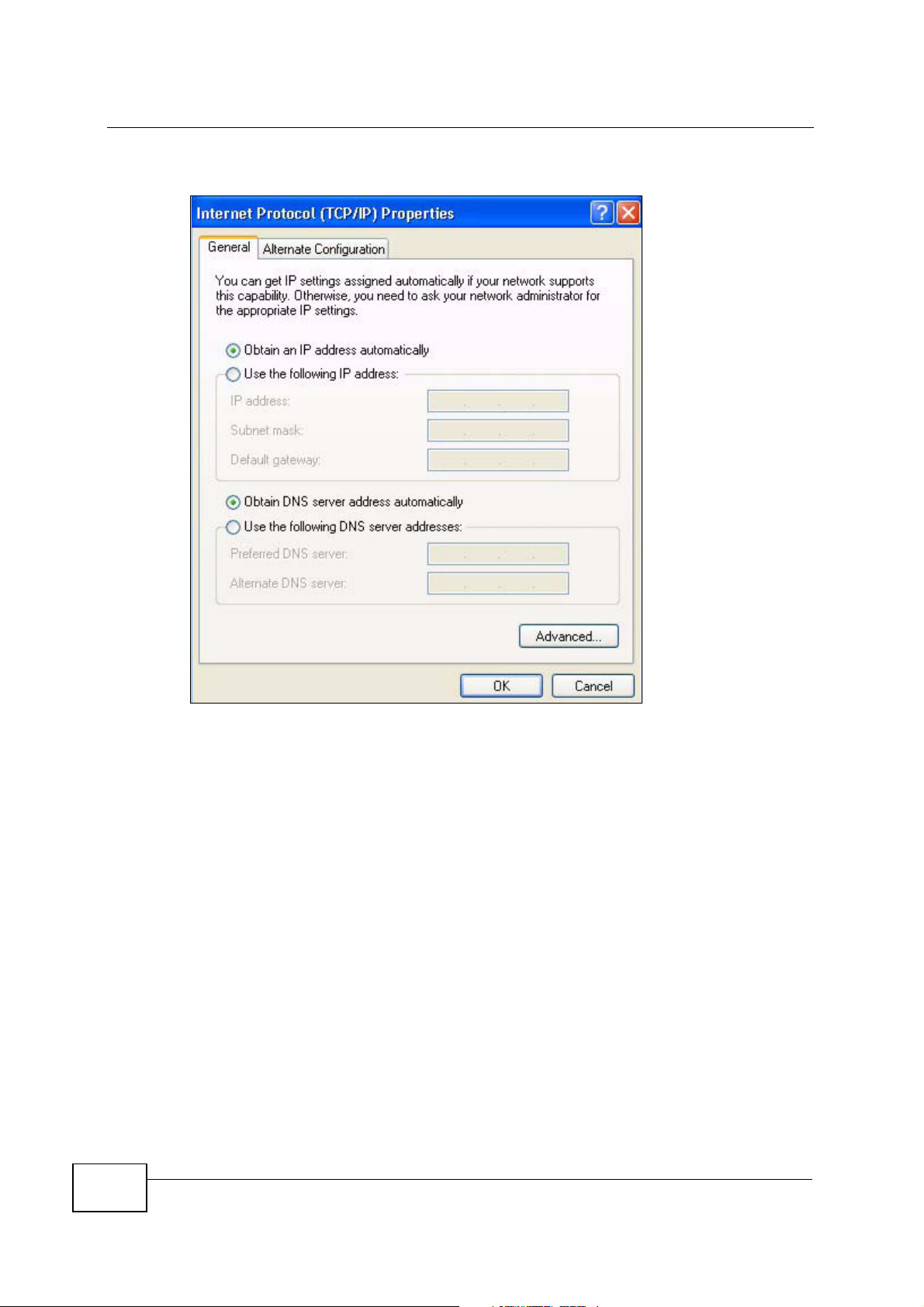
5 The Internet Protocol TCP/IP Properties window opens.
6 Select Obtain an IP address automatically if your network administrator or ISP
assigns your IP address dynamically.
Select Use the following IP Address and fill in the IP address, Subnet mask,
and Default gateway fields if you have a static IP address that was assigned to
you by your network administrator or ISP. You may also have to enter a Preferred
DNS server and an Alternate DNS server, if that information was provided.
7 Click OK to close the Internet Protocol (TCP/IP) Properties window.
8 Click OK to close the Local Area Connection Properties window.
Verifying Settings
1 Click Start > All Programs > Accessories > Command Prompt.
2 In the Command Prompt window, type "ipconfig" and then press [ENTER].
You can also go to Start > Control Panel > Network Connections, right-click a
network connection, click Status and then click the Support tab to view your IP
address and connection information.
250
NVG2053 User’s Guide

Windows Vista
This section shows screens from Windows Vista Professional.
1 Click Start > Control Panel.
2 In the Control Panel, click the Network and Internet icon.
Appendix B Setting Up Your Computer’s IP Address
3 Click the Network and Sharing Center icon.
NVG2053 User’s Guide
251

Appendix B Setting Up Your Computer’s IP Address
4 Click Manage network connections.
5 Right-click Local Area Connection and then select Properties.
252
Note: During this procedure, click Continue whenever Windows displays a screen
saying that it needs your permission to continue.
NVG2053 User’s Guide

Appendix B Setting Up Your Computer’s IP Address
6 Select Internet Protocol Version 4 (TCP/IPv4) and then select Properties.
NVG2053 User’s Guide
253

Appendix B Setting Up Your Computer’s IP Address
7 The Internet Protocol Version 4 (TCP/IPv4) Properties window opens.
8 Select Obtain an IP address automatically if your network administrator or ISP
assigns your IP address dynamically.
Select Use the following IP Address and fill in the IP address, Subnet mask,
and Default gateway fields if you have a static IP address that was assigned to
you by your network administrator or ISP. You may also have to enter a Preferred
DNS server and an Alternate DNS server, if that information was
provided.Click Advanced.
9 Click OK to close the Internet Protocol (TCP/IP) Properties window.
10 Click OK to close the Local Area Connection Properties window.
254
NVG2053 User’s Guide

Verifying Settings
1 Click Start > All Programs > Accessories > Command Prompt.
2 In the Command Prompt window, type "ipconfig" and then press [ENTER].
You can also go to Start > Control Panel > Network Connections, right-click a
network connection, click Status and then click the Support tab to view your IP
address and connection information.
Windows 7
This section shows screens from Windows 7 Enterprise.
1 Click Start > Control Panel.
Appendix B Setting Up Your Computer’s IP Address
2 In the Control Panel, click View network status and tasks under the
Network and Internet category.
NVG2053 User’s Guide
255

Appendix B Setting Up Your Computer’s IP Address
3 Click Change adapter settings.
4 Double click Local Area Connection and then select Properties.
256
Note: During this procedure, click Continue whenever Windows displays a screen
saying that it needs your permission to continue.
NVG2053 User’s Guide

Appendix B Setting Up Your Computer’s IP Address
5 Select Internet Protocol Version 4 (TCP/IPv4) and then select Properties.
NVG2053 User’s Guide
257

Appendix B Setting Up Your Computer’s IP Address
6 The Internet Protocol Version 4 (TCP/IPv4) Properties window opens.
7 Select Obtain an IP address automatically if your network administrator or ISP
assigns your IP address dynamically.
Select Use the following IP Address and fill in the IP address, Subnet mask,
and Default gateway fields if you have a static IP address that was assigned to
you by your network administrator or ISP. You may also have to enter a Preferred
DNS server and an Alternate DNS server, if that information was provided.
Click Advanced if you want to configure advanced settings for IP, DNS and WINS.
8 Click OK to close the Internet Protocol (TCP/IP) Properties window.
9 Click OK to close the Local Area Connection Properties window.
258
NVG2053 User’s Guide

Verifying Settings
1 Click Start > All Programs > Accessories > Command Prompt.
2 In the Command Prompt window, type "ipconfig" and then press [ENTER].
3 The IP settings are displayed as follows.
Appendix B Setting Up Your Computer’s IP Address
Mac OS X: 10.3 and 10.4
The screens in this section are from Mac OS X 10.4 but can also apply to 10.3.
1 Click Apple > System Preferences.
NVG2053 User’s Guide
259

Appendix B Setting Up Your Computer’s IP Address
2 In the System Preferences window, click the Network icon.
3 When the Network preferences pane opens, select Built-in Ethernet from the
network connection type list, and then click Configure.
260
NVG2053 User’s Guide

Appendix B Setting Up Your Computer’s IP Address
4 For dynamically assigned settings, select Using DHCP from the Configure IPv4
list in the TCP/IP tab.
5 For statically assigned settings, do the following:
•From the Configure IPv4 list, select Manually.
•In the IP Address field, type your IP address.
•In the Subnet Mask field, type your subnet mask.
•In the Router field, type the IP address of your device.
6 Click Apply Now and close the window.
NVG2053 User’s Guide
261

Appendix B Setting Up Your Computer’s IP Address
Verifying Settings
Check your TCP/IP properties by clicking Applications > Utilities > Network
Utilities, and then selecting the appropriate Network Interface from the Info
tab.
Figure 112 Mac OS X 10.4: Network Utility
Mac OS X: 10.5 and 10.6
The screens in this section are from Mac OS X 10.5 but can also apply to 10.6.
1 Click Apple > System Preferences.
262
NVG2053 User’s Guide

Appendix B Setting Up Your Computer’s IP Address
2 In System Preferences, click the Network icon.
3 When the Network preferences pane opens, select Ethernet from the list of
available connection types.
4 From the Configure list, select Using DHCP for dynamically assigned settings.
NVG2053 User’s Guide
263

Appendix B Setting Up Your Computer’s IP Address
5 For statically assigned settings, do the following:
•From the Configure list, select Manually.
•In the IP Address field, enter your IP address.
•In the Subnet Mask field, enter your subnet mask.
•In the Router field, enter the IP address of your NVG2053.
264
6 Click Apply and close the window.
NVG2053 User’s Guide

Verifying Settings
Check your TCP/IP properties by clicking Applications > Utilities > Network
Utilities, and then selecting the appropriate Network interface from the Info
tab.
Figure 113 Mac OS X 10.5: Network Utility
Appendix B Setting Up Your Computer’s IP Address
Linux: Ubuntu 8 (GNOME)
This section shows you how to configure your computer’s TCP/IP settings in the
GNU Object Model Environment (GNOME) using the Ubuntu 8 Linux distribution.
The procedure, screens and file locations may vary depending on your specific
distribution, release version, and individual configuration. The following screens
use the default Ubuntu 8 installation.
Note: Make sure you are logged in as the root administrator.
NVG2053 User’s Guide
265

Appendix B Setting Up Your Computer’s IP Address
Follow the steps below to configure your computer IP address in GNOME:
1 Click System > Administration > Network.
2 When the Network Settings window opens, click Unlock to open the
Authenticate window. (By default, the Unlock button is greyed out until clicked.)
You cannot make changes to your configuration unless you first enter your admin
password.
266
NVG2053 User’s Guide

Appendix B Setting Up Your Computer’s IP Address
3 In the Authenticate window, enter your admin account name and password then
click the Authenticate button.
4 In the Network Settings window, select the connection that you want to
configure, then click Properties.
NVG2053 User’s Guide
267

Appendix B Setting Up Your Computer’s IP Address
5 The Properties dialog box opens.
•In the Configuration list, select Automatic Configuration (DHCP) if you
have a dynamic IP address.
•In the Configuration list, select Static IP address if you have a static IP
address. Fill in the IP address, Subnet mask, and Gateway address fields.
6 Click OK to save the changes and close the Properties dialog box and return to
the Network Settings screen.
7 If you know your DNS server IP address(es), click the DNS tab in the Network
Settings window and then enter the DNS server information in the fields
provided.
268
8 Click the Close button to apply the changes.
NVG2053 User’s Guide

Verifying Settings
Check your TCP/IP properties by clicking System > Administration > Network
Tools, and then selecting the appropriate Network device from the Devices
tab. The Interface Statistics column shows data if your connection is working
properly.
Figure 114 Ubuntu 8: Network Tools
Appendix B Setting Up Your Computer’s IP Address
NVG2053 User’s Guide
269

Appendix B Setting Up Your Computer’s IP Address
Linux: openSUSE 10.3 (KDE)
This section shows you how to configure your computer’s TCP/IP settings in the K
Desktop Environment (KDE) using the openSUSE 10.3 Linux distribution. The
procedure, screens and file locations may vary depending on your specific
distribution, release version, and individual configuration. The following screens
use the default openSUSE 10.3 installation.
Note: Make sure you are logged in as the root administrator.
Follow the steps below to configure your computer IP address in the KDE:
1 Click K Menu > Computer > Administrator Settings (YaST).
270
2 When the Run as Root - KDE su dialog opens, enter the admin password and
click OK.
NVG2053 User’s Guide

Appendix B Setting Up Your Computer’s IP Address
3 When the YaST Control Center window opens, select Network Devices and
then click the Network Card icon.
4 When the Network Settings window opens, click the Overview tab, select the
appropriate connection Name from the list, and then click the Configure button.
NVG2053 User’s Guide
271

Appendix B Setting Up Your Computer’s IP Address
5 When the Network Card Setup window opens, click the Address tab
Figure 115 openSUSE 10.3: Network Card Setup
6 Select Dynamic Address (DHCP) if you have a dynamic IP address.
Select Statically assigned IP Address if you have a static IP address. Fill in the
IP address, Subnet mask, and Hostname fields.
7 Click Next to save the changes and close the Network Card Setup window.
272
NVG2053 User’s Guide

Appendix B Setting Up Your Computer’s IP Address
8 If you know your DNS server IP address(es), click the Hostname/DNS tab in
Network Settings and then enter the DNS server information in the fields
provided.
9 Click Finish to save your settings and close the window.
Verifying Settings
Click the KNetwork Manager icon on the Task bar to check your TCP/IP
properties. From the Options sub-menu, select Show Connection Information.
Figure 116 openSUSE 10.3: KNetwork Manager
NVG2053 User’s Guide
273

Appendix B Setting Up Your Computer’s IP Address
When the Connection Status - KNetwork Manager window opens, click the
Statistics tab to see if your connection is working properly.
Figure 117 openSUSE: Connection Status - KNetwork Manager
274
NVG2053 User’s Guide

APPENDIX C
Wireless LANs
Wireless LAN Topologies
This section discusses ad-hoc and infrastructure wireless LAN topologies.
Ad-hoc Wireless LAN Configuration
The simplest WLAN configuration is an independent (Ad-hoc) WLAN that connects
a set of computers with wireless adapters (A, B, C). Any time two or more wireless
adapters are within range of each other, they can set up an independent network,
which is commonly referred to as an ad-hoc network or Independent Basic Service
Set (IBSS). The following diagram shows an example of notebook computers
using wireless adapters to form an ad-hoc wireless LAN.
BSS
Figure 118 Peer-to-Peer Communication in an Ad-hoc Network
A Basic Service Set (BSS) exists when all communications between wireless
clients or between a wireless client and a wired network client go through one
access point (AP).
Intra-BSS traffic is traffic between wireless clients in the BSS. When Intra-BSS is
enabled, wireless client A and B can access the wired network and communicate
NVG2053 User’s Guide
275

Appendix C Wireless LANs
with each other. When Intra-BSS is disabled, wireless client A and B can still
access the wired network but cannot communicate with each other.
Figure 119 Basic Service Set
ESS
An Extended Service Set (ESS) consists of a series of overlapping BSSs, each
containing an access point, with each access point connected together by a wired
network. This wired connection between APs is called a Distribution System (DS).
This type of wireless LAN topology is called an Infrastructure WLAN. The Access
Points not only provide communication with the wired network but also mediate
wireless network traffic in the immediate neighborhood.
276
NVG2053 User’s Guide

Appendix C Wireless LANs
An ESSID (ESS IDentification) uniquely identifies each ESS. All access points and
their associated wireless clients within the same ESS must have the same ESSID
in order to communicate.
Figure 120 Infrastructure WLAN
Channel
A channel is the radio frequency(ies) used by wireless devices to transmit and
receive data. Channels available depend on your geographical area. You may have
a choice of channels (for your region) so you should use a channel different from
an adjacent AP (access point) to reduce interference. Interference occurs when
radio signals from different access points overlap causing interference and
degrading performance.
Adjacent channels partially overlap however. To avoid interference due to overlap,
your AP should be on a channel at least five channels away from a channel that an
adjacent AP is using. For example, if your region has 11 channels and an adjacent
AP is using channel 1, then you need to select a channel between 6 or 11.
RTS/CTS
A hidden node occurs when two stations are within range of the same access
point, but are not within range of each other. The following figure illustrates a
NVG2053 User’s Guide
277

Appendix C Wireless LANs
hidden node. Both stations (STA) are within range of the access point (AP) or
wireless gateway, but out-of-range of each other, so they cannot "hear" each
other, that is they do not know if the channel is currently being used. Therefore,
they are considered hidden from each other.
Figure 121 RTS/CTS
When station A sends data to the AP, it might not know that the station B is
already using the channel. If these two stations send data at the same time,
collisions may occur when both sets of data arrive at the AP at the same time,
resulting in a loss of messages for both stations.
RTS/CTS is designed to prevent collisions due to hidden nodes. An RTS/CTS
defines the biggest size data frame you can send before an RTS (Request To
Send)/CTS (Clear to Send) handshake is invoked.
When a data frame exceeds the RTS/CTS value you set (between 0 to 2432
bytes), the station that wants to transmit this frame must first send an RTS
(Request To Send) message to the AP for permission to send it. The AP then
responds with a CTS (Clear to Send) message to all other stations within its range
to notify them to defer their transmission. It also reserves and confirms with the
requesting station the time frame for the requested transmission.
Stations can send frames smaller than the specified RTS/CTS directly to the AP
without the RTS (Request To Send)/CTS (Clear to Send) handshake.
You should only configure RTS/CTS if the possibility of hidden nodes exists on
your network and the "cost" of resending large frames is more than the extra
network overhead involved in the RTS (Request To Send)/CTS (Clear to Send)
handshake.
If the RTS/CTS value is greater than the Fragmentation Threshold value (see
next), then the RTS (Request To Send)/CTS (Clear to Send) handshake will never
occur as data frames will be fragmented before they reach RTS/CTS size.
278
Note: Enabling the RTS Threshold causes redundant network overhead that could
negatively affect the throughput performance instead of providing a remedy.
NVG2053 User’s Guide

Fragmentation Threshold
A Fragmentation Threshold is the maximum data fragment size (between 256
and 2432 bytes) that can be sent in the wireless network before the AP will
fragment the packet into smaller data frames.
A large Fragmentation Threshold is recommended for networks not prone to
interference while you should set a smaller threshold for busy networks or
networks that are prone to interference.
If the Fragmentation Threshold value is smaller than the RTS/CTS value (see
previously) you set then the RTS (Request To Send)/CTS (Clear to Send)
handshake will never occur as data frames will be fragmented before they reach
RTS/CTS size.
Preamble Type
Preamble is used to signal that data is coming to the receiver. Short and long refer
to the length of the synchronization field in a packet.
Appendix C Wireless LANs
Short preamble increases performance as less time sending preamble means
more time for sending data. All IEEE 802.11 compliant wireless adapters support
long preamble, but not all support short preamble.
Use long preamble if you are unsure what preamble mode other wireless devices
on the network support, and to provide more reliable communications in busy
wireless networks.
Use short preamble if you are sure all wireless devices on the network support it,
and to provide more efficient communications.
Use the dynamic setting to automatically use short preamble when all wireless
devices on the network support it, otherwise the NVG2053 uses long preamble.
Note: The wireless devices MUST use the same preamble mode in order to
communicate.
IEEE 802.11g Wireless LAN
IEEE 802.11g is fully compatible with the IEEE 802.11b standard. This means an
IEEE 802.11b adapter can interface directly with an IEEE 802.11g access point
(and vice versa) at 11 Mbps or lower depending on range. IEEE 802.11g has
NVG2053 User’s Guide
279

Appendix C Wireless LANs
several intermediate rate steps between the maximum and minimum data rates.
The IEEE 802.11g data rate and modulation are as follows:
Table 80 IEEE 802.11g
DATA RATE
(MBPS)
1 DBPSK (Differential Binary Phase Shift Keyed)
2 DQPSK (Differential Quadrature Phase Shift Keying)
5.5 / 11 CCK (Complementary Code Keying)
6/9/12/18/24/36/
48/54
MODULATION
OFDM (Orthogonal Frequency Division Multiplexing)
Wireless Security Overview
Wireless security is vital to your network to protect wireless communication
between wireless clients, access points and the wired network.
Wireless security methods available on the NVG2053 are data encryption, wireless
client authentication, restricting access by device MAC address and hiding the
NVG2053 identity.
The following figure shows the relative effectiveness of these wireless security
methods available on your NVG2053.
Table 81 Wireless Security Levels
SECURITY
LEVEL
Least
Secure
Most Secure
SECURITY TYPE
Unique SSID (Default)
Unique SSID with Hide SSID Enabled
MAC Address Filtering
WEP Encryption
IEEE802.1x EAP with RADIUS Server
Authentication
Wi-Fi Protected Access (WPA)
WPA2
Note: You must enable the same wireless security settings on the NVG2053 and on
all wireless clients that you want to associate with it.
280
NVG2053 User’s Guide

IEEE 802.1x
In June 2001, the IEEE 802.1x standard was designed to extend the features of
IEEE 802.11 to support extended authentication as well as providing additional
accounting and control features. It is supported by Windows XP and a number of
network devices. Some advantages of IEEE 802.1x are:
• User based identification that allows for roaming.
• Support for RADIUS (Remote Authentication Dial In User Service, RFC 2138,
2139) for centralized user profile and accounting management on a network
RADIUS server.
• Support for EAP (Extensible Authentication Protocol, RFC 2486) that allows
additional authentication methods to be deployed with no changes to the access
point or the wireless clients.
RADIUS
RADIUS is based on a client-server model that supports authentication,
authorization and accounting. The access point is the client and the server is the
RADIUS server. The RADIUS server handles the following tasks:
Appendix C Wireless LANs
• Authentication
Determines the identity of the users.
• Authorization
Determines the network services available to authenticated users once they are
connected to the network.
•Accounting
Keeps track of the client’s network activity.
RADIUS is a simple package exchange in which your AP acts as a message relay
between the wireless client and the network RADIUS server.
Types of RADIUS Messages
The following types of RADIUS messages are exchanged between the access point
and the RADIUS server for user authentication:
• Access-Request
Sent by an access point requesting authentication.
• Access-Reject
Sent by a RADIUS server rejecting access.
• Access-Accept
Sent by a RADIUS server allowing access.
NVG2053 User’s Guide
281

Appendix C Wireless LANs
• Access-Challenge
Sent by a RADIUS server requesting more information in order to allow access.
The access point sends a proper response from the user and then sends another
Access-Request message.
The following types of RADIUS messages are exchanged between the access point
and the RADIUS server for user accounting:
•Accounting-Request
Sent by the access point requesting accounting.
• Accounting-Response
Sent by the RADIUS server to indicate that it has started or stopped accounting.
In order to ensure network security, the access point and the RADIUS server use a
shared secret key, which is a password, they both know. The key is not sent over
the network. In addition to the shared key, password information exchanged is
also encrypted to protect the network from unauthorized access.
Types of EAP Authentication
This section discusses some popular authentication types: EAP-MD5, EAP-TLS,
EAP-TTLS, PEAP and LEAP. Your wireless LAN device may not support all
authentication types.
EAP (Extensible Authentication Protocol) is an authentication protocol that runs on
top of the IEEE 802.1x transport mechanism in order to support multiple types of
user authentication. By using EAP to interact with an EAP-compatible RADIUS
server, an access point helps a wireless station and a RADIUS server perform
authentication.
The type of authentication you use depends on the RADIUS server and an
intermediary AP(s) that supports IEEE 802.1x. .
For EAP-TLS authentication type, you must first have a wired connection to the
network and obtain the certificate(s) from a certificate authority (CA). A certificate
(also called digital IDs) can be used to authenticate users and a CA issues
certificates and guarantees the identity of each certificate owner.
EAP-MD5 (Message-Digest Algorithm 5)
282
MD5 authentication is the simplest one-way authentication method. The
authentication server sends a challenge to the wireless client. The wireless client
‘proves’ that it knows the password by encrypting the password with the challenge
and sends back the information. Password is not sent in plain text.
NVG2053 User’s Guide

However, MD5 authentication has some weaknesses. Since the authentication
server needs to get the plaintext passwords, the passwords must be stored. Thus
someone other than the authentication server may access the password file. In
addition, it is possible to impersonate an authentication server as MD5
authentication method does not perform mutual authentication. Finally, MD5
authentication method does not support data encryption with dynamic session
key. You must configure WEP encryption keys for data encryption.
EAP-TLS (Transport Layer Security)
With EAP-TLS, digital certifications are needed by both the server and the wireless
clients for mutual authentication. The server presents a certificate to the client.
After validating the identity of the server, the client sends a different certificate to
the server. The exchange of certificates is done in the open before a secured
tunnel is created. This makes user identity vulnerable to passive attacks. A digital
certificate is an electronic ID card that authenticates the sender’s identity.
However, to implement EAP-TLS, you need a Certificate Authority (CA) to handle
certificates, which imposes a management overhead.
Appendix C Wireless LANs
EAP-TTLS (Tunneled Transport Layer Service)
EAP-TTLS is an extension of the EAP-TLS authentication that uses certificates for
only the server-side authentications to establish a secure connection. Client
authentication is then done by sending username and password through the
secure connection, thus client identity is protected. For client authentication, EAPTTLS supports EAP methods and legacy authentication methods such as PAP,
CHAP, MS-CHAP and MS-CHAP v2.
PEAP (Protected EAP)
Like EAP-TTLS, server-side certificate authentication is used to establish a secure
connection, then use simple username and password methods through the
secured connection to authenticate the clients, thus hiding client identity.
However, PEAP only supports EAP methods, such as EAP-MD5, EAP-MSCHAPv2
and EAP-GTC (EAP-Generic Token Card), for client authentication. EAP-GTC is
implemented only by Cisco.
LEAP
LEAP (Lightweight Extensible Authentication Protocol) is a Cisco implementation of
IEEE 802.1x.
NVG2053 User’s Guide
283

Appendix C Wireless LANs
Dynamic WEP Key Exchange
The AP maps a unique key that is generated with the RADIUS server. This key
expires when the wireless connection times out, disconnects or reauthentication
times out. A new WEP key is generated each time reauthentication is performed.
If this feature is enabled, it is not necessary to configure a default encryption key
in the wireless security configuration screen. You may still configure and store
keys, but they will not be used while dynamic WEP is enabled.
Note: EAP-MD5 cannot be used with Dynamic WEP Key Exchange
For added security, certificate-based authentications (EAP-TLS, EAP-TTLS and
PEAP) use dynamic keys for data encryption. They are often deployed in corporate
environments, but for public deployment, a simple user name and password pair
is more practical. The following table is a comparison of the features of
authentication types.
Table 82 Comparison of EAP Authentication Types
EAP-MD5 EAP-TLS EAP-TTLS PEAP LEAP
Mutual Authentication No Yes Yes Yes Yes
Certificate – Client No Yes Optional Optional No
Certificate – Server No Yes Yes Yes No
Dynamic Key Exchange No Yes Yes Yes Yes
Credential Integrity None Strong Strong Strong Moderate
Deployment Difficulty Easy Hard Moderate Moderate Moderate
Client Identity
Protection
No No Yes Yes No
WPA and WPA2
Wi-Fi Protected Access (WPA) is a subset of the IEEE 802.11i standard. WPA2
(IEEE 802.11i) is a wireless security standard that defines stronger encryption,
authentication and key management than WPA.
Key differences between WPA or WPA2 and WEP are improved data encryption and
user authentication.
If both an AP and the wireless clients support WPA2 and you have an external
RADIUS server, use WPA2 for stronger data encryption. If you don't have an
external RADIUS server, you should use WPA2-PSK (WPA2-Pre-Shared Key) that
only requires a single (identical) password entered into each access point, wireless
gateway and wireless client. As long as the passwords match, a wireless client will
be granted access to a WLAN.
284
NVG2053 User’s Guide

If the AP or the wireless clients do not support WPA2, just use WPA or WPA-PSK
depending on whether you have an external RADIUS server or not.
Select WEP only when the AP and/or wireless clients do not support WPA or WPA2.
WEP is less secure than WPA or WPA2.
Encryption
WPA improves data encryption by using Temporal Key Integrity Protocol (TKIP),
Message Integrity Check (MIC) and IEEE 802.1x. WPA2 also uses TKIP when
required for compatibility reasons, but offers stronger encryption than TKIP with
Advanced Encryption Standard (AES) in the Counter mode with Cipher block
chaining Message authentication code Protocol (CCMP).
TKIP uses 128-bit keys that are dynamically generated and distributed by the
authentication server. AES (Advanced Encryption Standard) is a block cipher that
uses a 256-bit mathematical algorithm called Rijndael. They both include a perpacket key mixing function, a Message Integrity Check (MIC) named Michael, an
extended initialization vector (IV) with sequencing rules, and a re-keying
mechanism.
Appendix C Wireless LANs
WPA and WPA2 regularly change and rotate the encryption keys so that the same
encryption key is never used twice.
The RADIUS server distributes a Pairwise Master Key (PMK) key to the AP that
then sets up a key hierarchy and management system, using the PMK to
dynamically generate unique data encryption keys to encrypt every data packet
that is wirelessly communicated between the AP and the wireless clients. This all
happens in the background automatically.
The Message Integrity Check (MIC) is designed to prevent an attacker from
capturing data packets, altering them and resending them. The MIC provides a
strong mathematical function in which the receiver and the transmitter each
compute and then compare the MIC. If they do not match, it is assumed that the
data has been tampered with and the packet is dropped.
By generating unique data encryption keys for every data packet and by creating
an integrity checking mechanism (MIC), with TKIP and AES it is more difficult to
decrypt data on a Wi-Fi network than WEP and difficult for an intruder to break
into the network.
The encryption mechanisms used for WPA(2) and WPA(2)-PSK are the same. The
only difference between the two is that WPA(2)-PSK uses a simple common
password, instead of user-specific credentials. The common-password approach
makes WPA(2)-PSK susceptible to brute-force password-guessing attacks but it’s
still an improvement over WEP as it employs a consistent, single, alphanumeric
password to derive a PMK which is used to generate unique temporal encryption
NVG2053 User’s Guide
285

Appendix C Wireless LANs
keys. This prevent all wireless devices sharing the same encryption keys. (a
weakness of WEP)
User Authentication
WPA and WPA2 apply IEEE 802.1x and Extensible Authentication Protocol (EAP) to
authenticate wireless clients using an external RADIUS database. WPA2 reduces
the number of key exchange messages from six to four (CCMP 4-way handshake)
and shortens the time required to connect to a network. Other WPA2
authentication features that are different from WPA include key caching and preauthentication. These two features are optional and may not be supported in all
wireless devices.
Key caching allows a wireless client to store the PMK it derived through a
successful authentication with an AP. The wireless client uses the PMK when it tries
to connect to the same AP and does not need to go with the authentication
process again.
Pre-authentication enables fast roaming by allowing the wireless client (already
connecting to an AP) to perform IEEE 802.1x authentication with another AP
before connecting to it.
Wireless Client WPA Supplicants
A wireless client supplicant is the software that runs on an operating system
instructing the wireless client how to use WPA. At the time of writing, the most
widely available supplicant is the WPA patch for Windows XP, Funk Software's
Odyssey client.
The Windows XP patch is a free download that adds WPA capability to Windows
XP's built-in "Zero Configuration" wireless client. However, you must run Windows
XP to use it.
WPA(2) with RADIUS Application Example
To set up WPA(2), you need the IP address of the RADIUS server, its port number
(default is 1812), and the RADIUS shared secret. A WPA(2) application example
with an external RADIUS server looks as follows. "A" is the RADIUS server. "DS" is
the distribution system.
1 The AP passes the wireless client's authentication request to the RADIUS server.
2 The RADIUS server then checks the user's identification against its database and
grants or denies network access accordingly.
286
3 A 256-bit Pairwise Master Key (PMK) is derived from the authentication process by
the RADIUS server and the client.
NVG2053 User’s Guide

Appendix C Wireless LANs
4 The RADIUS server distributes the PMK to the AP. The AP then sets up a key
hierarchy and management system, using the PMK to dynamically generate
unique data encryption keys. The keys are used to encrypt every data packet that
is wirelessly communicated between the AP and the wireless clients.
Figure 122 WPA(2) with RADIUS Application Example
WPA(2)-PSK Application Example
A WPA(2)-PSK application looks as follows.
1 First enter identical passwords into the AP and all wireless clients. The Pre-Shared
Key (PSK) must consist of between 8 and 63 ASCII characters or 64 hexadecimal
characters (including spaces and symbols).
2 The AP checks each wireless client's password and allows it to join the network
only if the password matches.
3 The AP and wireless clients generate a common PMK (Pairwise Master Key). The
key itself is not sent over the network, but is derived from the PSK and the SSID.
NVG2053 User’s Guide
287

Appendix C Wireless LANs
4 The AP and wireless clients use the TKIP or AES encryption process, the PMK and
information exchanged in a handshake to create temporal encryption keys. They
use these keys to encrypt data exchanged between them.
Figure 123 WPA(2)-PSK Authentication
Security Parameters Summary
Refer to this table to see what other security parameters you should configure for
each authentication method or key management protocol type. MAC address
filters are not dependent on how you configure these security features.
Table 83 Wireless Security Relational Matrix
AUTHENTICATION
METHOD/ KEY
MANAGEMENT
PROTOCOL
Open None No Disable
Open WEP No Enable with Dynamic WEP Key
Shared WEP No Enable with Dynamic WEP Key
WPA TKIP/AES No Enable
WPA-PSK TKIP/AES Yes Disable
WPA2 TKIP/AES No Enable
WPA2-PSK TKIP/AES Yes Disable
ENCRYPTIO
N METHOD
ENTER
MANUAL KEY
Yes Enable without Dynamic WEP
Yes Disable
Yes Enable without Dynamic WEP
Yes Disable
IEEE 802.1X
Enable without Dynamic WEP
Key
Key
Key
288
NVG2053 User’s Guide

Antenna Overview
An antenna couples RF signals onto air. A transmitter within a wireless device
sends an RF signal to the antenna, which propagates the signal through the air.
The antenna also operates in reverse by capturing RF signals from the air.
Positioning the antennas properly increases the range and coverage area of a
wireless LAN.
Antenna Characteristics
Frequency
An antenna in the frequency of 2.4GHz (IEEE 802.11b and IEEE 802.11g) or 5GHz
(IEEE 802.11a) is needed to communicate efficiently in a wireless LAN
Radiation Pattern
Appendix C Wireless LANs
A radiation pattern is a diagram that allows you to visualize the shape of the
antenna’s coverage area.
Antenna Gain
Antenna gain, measured in dB (decibel), is the increase in coverage within the RF
beam width. Higher antenna gain improves the range of the signal for better
communications.
For an indoor site, each 1 dB increase in antenna gain results in a range increase
of approximately 2.5%. For an unobstructed outdoor site, each 1dB increase in
gain results in a range increase of approximately 5%. Actual results may vary
depending on the network environment.
Antenna gain is sometimes specified in dBi, which is how much the antenna
increases the signal power compared to using an isotropic antenna. An isotropic
antenna is a theoretical perfect antenna that sends out radio signals equally well
in all directions. dBi represents the true gain that the antenna provides.
Types of Antennas for WLAN
There are two types of antennas used for wireless LAN applications.
NVG2053 User’s Guide
289

Appendix C Wireless LANs
• Omni-directional antennas send the RF signal out in all directions on a horizontal
plane. The coverage area is torus-shaped (like a donut) which makes these
antennas ideal for a room environment. With a wide coverage area, it is possible
to make circular overlapping coverage areas with multiple access points.
• Directional antennas concentrate the RF signal in a beam, like a flashlight does
with the light from its bulb. The angle of the beam determines the width of the
coverage pattern. Angles typically range from 20 degrees (very directional) to
120 degrees (less directional). Directional antennas are ideal for hallways and
outdoor point-to-point applications.
Positioning Antennas
In general, antennas should be mounted as high as practically possible and free of
obstructions. In point-to–point application, position both antennas at the same
height and in a direct line of sight to each other to attain the best performance.
For omni-directional antennas mounted on a table, desk, and so on, point the
antenna up. For omni-directional antennas mounted on a wall or ceiling, point the
antenna down. For a single AP application, place omni-directional antennas as
close to the center of the coverage area as possible.
For directional antennas, point the antenna in the direction of the desired
coverage area.
290
NVG2053 User’s Guide

APPENDIX D
Legal Information
Copyright
Copyright © 2011 by ZyXEL Communications Corporation.
The contents of this publication may not be reproduced in any part or as a whole,
transcribed, stored in a retrieval system, translated into any language, or
transmitted in any form or by any means, electronic, mechanical, magnetic,
optical, chemical, photocopying, manual, or otherwise, without the prior written
permission of ZyXEL Communications Corporation.
Published by ZyXEL Communications Corporation. All rights reserved.
Disclaimer
ZyXEL does not assume any liability arising out of the application or use of any
products, or software described herein. Neither does it convey any license under
its patent rights nor the patent rights of others. ZyXEL further reserves the right
to make changes in any products described herein without notice. This publication
is subject to change without notice.
Your use of the NVG2053 is subject to the terms and conditions of any related
service providers.
Certifications
Federal Communications Commission (FCC) Interference Statement
The device complies with Part 15 of FCC rules. Operation is subject to the
following two conditions:
• This device may not cause harmful interference.
• This device must accept any interference received, including interference that
may cause undesired operations.
This device has been tested and found to comply with the limits for a Class B
digital device pursuant to Part 15 of the FCC Rules. These limits are designed to
NVG2053 User’s Guide
291

Appendix D Legal Information
provide reasonable protection against harmful interference in a residential
installation. This device generates, uses, and can radiate radio frequency energy,
and if not installed and used in accordance with the instructions, may cause
harmful interference to radio communications. However, there is no guarantee
that interference will not occur in a particular installation.
If this device does cause harmful interference to radio/television reception, which
can be determined by turning the device off and on, the user is encouraged to try
to correct the interference by one or more of the following measures:
1 Reorient or relocate the receiving antenna.
2 Increase the separation between the equipment and the receiver.
3 Connect the equipment into an outlet on a circuit different from that to which the
receiver is connected.
4 Consult the dealer or an experienced radio/TV technician for help.
FCC Radiation Exposure Statement
• This transmitter must not be co-located or operating in conjunction with any
other antenna or transmitter.
• IEEE 802.11b or 802.11g operation of this product in the U.S.A. is firmwarelimited to channels 1 through 11.
• To comply with FCC RF exposure compliance requirements, a separation
distance of at least 20 cm must be maintained between the antenna of this
device and all persons.
Industry Canada Statement
This device complies with RSS-210 of the Industry Canada Rules. Operation is
subject to the following two conditions:
1) this device may not cause interference and
2) this device must accept any interference, including interference that may cause
undesired operation of the device
This device has been designed to operate with an antenna having a maximum
gain of 2dBi.
292
Antenna having a higher gain is strictly prohibited per regulations of Industry
Canada. The required antenna impedance is 50 ohms.
NVG2053 User’s Guide

Appendix D Legal Information
To reduce potential radio interference to other users, the antenna type and its gain
should be so chosen that the EIRP is not more than required for successful
communication.
IMPORTANT NOTE
Device for the band 5150-5250 MHz is only for indoor usage to reduce potential
for harmful interference to co-channel mobile satellite systems; users should also
be cautioned to take note that high-power radars are allocated as primary users
(meaning they have priority) of the bands 5250-5350 MHz and 5650-5850 MHz
and these radars could cause interference and/or damage to LE-LAN devices.
IC Radiation Exposure Statement:
This equipment complies with IC radiation exposure limits set forth for an
uncontrolled environment. This equipment should be installed and operated with
minimum distance 20cm between the radiator & your body.
注意 !
依據 低功率電波輻射性電機管理辦法
第十二條 經型式認證合格之低功率射頻電機,非經許可,公司、商號或使用
者均不得擅自變更頻率、加大功率或變更原設計之特性及功能。
第十四條 低功率射頻電機之使用不得影響飛航安全及干擾合法通信;經發現
有干擾現象時,應立即停用,並改善至無干擾時方得繼續使用。
前項合法通信,指依電信規定作業之無線電信。低功率射頻電機須忍
受合法通信或工業、科學及醫療用電波輻射性電機設備之干擾。
本機限在不干擾合法電臺與不受被干擾保障條件下於室內使用。
減少電磁波影響,請妥適使用。
Notices
Changes or modifications not expressly approved by the party responsible for
compliance could void the user's authority to operate the equipment.
This device has been designed for the WLAN 2.4 GHz network throughout the EC
region and Switzerland, with restrictions in France.
This Class B digital apparatus complies with Canadian ICES-003.
Cet appareil numérique de la classe B est conforme à la norme NMB-003 du
Canada.
NVG2053 User’s Guide
293

Appendix D Legal Information
Viewing Certifications
1 Go to http://www.zyxel.com.
2 Select your product on the ZyXEL home page to go to that product's page.
3 Select the certification you wish to view from this page.
ZyXEL Limited Warranty
ZyXEL warrants to the original end user (purchaser) that this product is free from
any defects in materials or workmanship for a period of up to two years from the
date of purchase. During the warranty period, and upon proof of purchase, should
the product have indications of failure due to faulty workmanship and/or
materials, ZyXEL will, at its discretion, repair or replace the defective products or
components without charge for either parts or labor, and to whatever extent it
shall deem necessary to restore the product or components to proper operating
condition. Any replacement will consist of a new or re-manufactured functionally
equivalent product of equal or higher value, and will be solely at the discretion of
ZyXEL. This warranty shall not apply if the product has been modified, misused,
tampered with, damaged by an act of God, or subjected to abnormal working
conditions.
Note
Repair or replacement, as provided under this warranty, is the exclusive remedy of
the purchaser. This warranty is in lieu of all other warranties, express or implied,
including any implied warranty of merchantability or fitness for a particular use or
purpose. ZyXEL shall in no event be held liable for indirect or consequential
damages of any kind to the purchaser.
To obtain the services of this warranty, contact your vendor. You may also refer to
the warranty policy for the region in which you bought the device at http://
www.zyxel.com/web/support_warranty_info.php.
Registration
Register your product online to receive e-mail notices of firmware upgrades and
information at www.zyxel.com for global products, or at www.us.zyxel.com for
North American products.
294
NVG2053 User’s Guide

APPENDIX E
Open Software Announcements
End-User License Agreement for "NVG2053"
WARNING: ZyXEL Communications Corp. IS WILLING TO
LICENSE THE SOFTWARE TO YOU ONLY UPON THE CONDITION
THAT YOU ACCEPT ALL OF THE TERMS CONTAINED IN THIS
LICENSE AGREEMENT. PLEASE READ THE TERMS CAREFULLY
BEFORE COMPLETING THE INSTALLATION PROCESS AS
INSTALLING THE SOFTWARE WILL INDICATE YOUR ASSENT TO
THEM. IF YOU DO NOT AGREE TO THESE TERMS, THEN ZyXEL
IS UNWILLING TO LICENSE THE SOFTWARE TO YOU, IN WHICH
EVENT YOU SHOULD RETURN THE UNINSTALLED SOFTWARE
AND PACKAGING TO THE PLACE FROM WHICH IT WAS
ACQUIRED OR ZyXEL, AND YOUR MONEY WILL BE REFUNDED.
HOWEVER, CERTAIN ZYXEL'S PRODUCTS MAY CONTAIN-IN
PART-SOME THIRD PARTY'S FREE AND OPEN SOFTWARE
PROGRAMS WHICH ALLOW YOU TO FREELY COPY, RUN,
DISTRIBUTE, MODIFY AND IMPROVE THE SOFTWARE UNDER
THE APPLICABLE TERMS OF SUCH THRID PARTY'S LICENSES
("OPEN-SOURCED COMPONENTS"). THE OPEN-SOURCED
COMPONENTS ARE LISTED IN THE NOTICE OR APPENDIX
BELOW. ZYXEL MAY HAVE DISTRIBUTED TO YOU HARDWARE
AND/OR SOFTWARE, OR MADE AVAILABLE FOR ELECTRONIC
DOWNLOADS THESE FREE SOFTWARE PROGRAMS OF THRID
PARTIES AND YOU ARE LICENSED TO FREELY COPY, MODIFY
AND REDISTIBUTE THAT SOFTWARE UNDER THE APPLICABLE
LICENSE TERMS OF SUCH THIRD PARTY. NONE OF THE
STATEMENTS OR DOCUMENTATION FROM ZYXEL INCLUDING
ANY RESTRICTIONS OR CONDITIONS STATED IN THIS END USER
LICENSE AGREEMENT SHALL RESTRICT ANY RIGHTS AND
LICENSES YOU MAY HAVE WITH RESPECT TO THE OPENSOURCED COMPONENTS UNDER THE APPLICABLE LICENSE
TERMS OF SUCH THIRD PARTY.
1 Grant of License for Personal Use
NVG2053 User’s Guide
295

Appendix E Open Software Announcements
ZyXEL Communications Corp. ("ZyXEL") grants you a non-exclusive, nonsublicense, non-transferable license to use the program with which this license is
distributed (the "Software"), including any documentation files accompanying the
Software ("Documentation"), for internal business use only, for up to the number
of users specified in sales order and invoice. You have the right to make one
backup copy of the Software and Documentation solely for archival, back-up or
disaster recovery purposes. You shall not exceed the scope of the license granted
hereunder. Any rights not expressly granted by ZyXEL to you are reserved by
ZyXEL, and all implied licenses are disclaimed.
2 Ownership
You have no ownership rights in the Software. Rather, you have a license to use
the Software as long as this License Agreement remains in full force and effect.
Ownership of the Software, Documentation and all intellectual property rights
therein shall remain at all times with ZyXEL. Any other use of the Software by any
other entity is strictly forbidden and is a violation of this License Agreement.
3 Copyright
The Software and Documentation contain material that is protected by
international copyright law, trade secret law, international treaty provisions, and
the applicable national laws of each respective country. All rights not granted to
you herein are expressly reserved by ZyXEL. You may not remove any proprietary
notice of ZyXEL or any of its licensors from any copy of the Software or
Documentation.
4 Restrictions
You may not publish, display, disclose, sell, rent, lease, modify, store, loan,
distribute, or create derivative works of the Software, or any part thereof. You
may not assign, sublicense, convey or otherwise transfer, pledge as security or
otherwise encumber the rights and licenses granted hereunder with respect to the
Software. ZyXEL is not obligated to provide any maintenance, technical or other
support for the resultant modified Software. You may not copy, reverse engineer,
decompile, reverse compile, translate, adapt, or disassemble the Software, or any
part thereof, nor shall you attempt to create the source code from the object code
for the Software. Except as and only to the extent expressly permitted in this
License, you may not market, co-brand, and private label or otherwise permit
third parties to link to the Software, or any part thereof. You may not use the
Software, or any part thereof, in the operation of a service bureau or for the
benefit of any other person or entity. You may not cause, assist or permit any
third party to do any of the foregoing. Portions of the Software utilize or include
third party software and other copyright material. Acknowledgements, licensing
terms and disclaimers for such material are contained in the License Notice as
below for the third party software, and your use of such material is exclusively
governed by their respective terms. ZyXEL has provided, as part of the Software
296
NVG2053 User’s Guide

Appendix E Open Software Announcements
package, access to certain third party software as a convenience. To the extent
that the Software contains third party software, ZyXEL has no express or implied
obligation to provide any technical or other support for such software other than
compliance with the applicable license terms of such third party, and makes no
warranty (express, implied or statutory) whatsoever with respect thereto. Please
contact the appropriate software vendor or manufacturer directly for technical
support and customer service related to its software and products.
5 Confidentiality
You acknowledge that the Software contains proprietary trade secrets of ZyXEL
and you hereby agree to maintain the confidentiality of the Software using at least
as great a degree of care as you use to maintain the confidentiality of your own
most confidential information. You agree to reasonably communicate the terms
and conditions of this License Agreement to those persons employed by you who
come into contact with the Software, and to use reasonable best efforts to ensure
their compliance with such terms and conditions, including, without limitation, not
knowingly permitting such persons to use any portion of the Software for the
purpose of deriving the source code of the Software.
6 No Warranty
THE SOFTWARE IS PROVIDED "AS IS." TO THE MAXIMUM EXTENT PERMITTED BY
LAW, ZyXEL DISCLAIMS ALL WARRANTIES OF ANY KIND, EITHER EXPRESSED OR
IMPLIED, INCLUDING, WITHOUT LIMITATION, IMPLIED WARRANTIES OF
MERCHANTABILITY AND FITNESS FOR A PARTICULAR PURPOSE, AND NONINFRINGEMENT. ZyXEL DOES NOT WARRANT THAT THE FUNCTIONS CONTAINED
IN THE SOFTWARE WILL MEET ANY REQUIREMENTS OR NEEDS YOU MAY HAVE,
OR THAT THE SOFTWARE WILL OPERATE ERROR FREE, OR IN AN UNINTERUPTED
FASHION, OR THAT ANY DEFECTS OR ERRORS IN THE SOFTWARE WILL BE
CORRECTED, OR THAT THE SOFTWARE IS COMPATIBLE WITH ANY PARTICULAR
PLATFORM. SOME JURISDICTIONS DO NOT ALLOW THE WAIVER OR EXCLUSION
OF IMPLIED WARRANTIES SO THEY MAY NOT APPLY TO YOU. IF THIS EXCLUSION
IS HELD TO BE UNENFORCEABLE BY A COURT OF COMPETENT JURISDICTION,
THEN ALL EXPRESS AND IMPLIED WARRANTIES SHALL BE LIMITED IN DURATION
TO A PERIOD OF THIRTY (30) DAYS FROM THE DATE OF PURCHASE OF THE
SOFTWARE, AND NO WARRANTIES SHALL APPLY AFTER THAT PERIOD.
7 Limitation of Liability
IN NO EVENT WILL ZyXEL BE LIABLE TO YOU OR ANY THIRD PARTY FOR ANY
INCIDENTAL OR CONSEQUENTIAL DAMAGES (INCLUDING, WITHOUT LIMITATION,
INDIRECT, SPECIAL, PUNITIVE, OR EXEMPLARY DAMAGES FOR LOSS OF
BUSINESS, LOSS OF PROFITS, BUSINESS INTERRUPTION, OR LOSS OF BUSINESS
INFORMATION) ARISING OUT OF THE USE OF OR INABILITY TO USE THE
SOFTWARE OR PROGRAM, OR FOR ANY CLAIM BY ANY OTHER PARTY, EVEN IF
ZyXEL HAS BEEN ADVISED OF THE POSSIBILITY OF SUCH DAMAGES. ZyXEL's
NVG2053 User’s Guide
297

Appendix E Open Software Announcements
TOTAL AGGREGATE LIABILITY WITH RESPECT TO ITS OBLIGATIONS UNDER THIS
AGREEMENT OR OTHERWISE WITH RESPECT TO THE SOFTWARE AND
DOCUMENTATION OR OTHERWISE SHALL BE EQUAL TO THE PURCHASE PRICE,
BUT SHALL IN NO EVENT EXCEED THE PRODUCT'S PRICE. BECAUSE SOME
STATES/COUNTRIES DO NOT ALLOW THE EXCLUSION OR LIMITATION OF
LIABILITY FOR CONSEQUENTIAL OR INCIDENTAL DAMAGES, THE ABOVE
LIMITATION MAY NOT APPLY TO YOU.
8 Export Restrictions
THIS LICENSE AGREEMENT IS EXPRESSLY MADE SUBJECT TO ANY APPLICABLE
LAWS, REGULATIONS, ORDERS, OR OTHER RESTRICTIONS ON THE EXPORT OF
THE SOFTWARE OR INFORMATION ABOUT SUCH SOFTWARE WHICH MAY BE
IMPOSED FROM TIME TO TIME. YOU SHALL NOT EXPORT THE SOFTWARE,
DOCUMENTATION OR INFORMATION ABOUT THE SOFTWARE AND
DOCUMENTATION WITHOUT COMPLYING WITH SUCH LAWS, REGULATIONS,
ORDERS, OR OTHER RESTRICTIONS. YOU AGREE TO INDEMNIFY ZyXEL AGAINST
ALL CLAIMS, LOSSES, DAMAGES, LIABILITIES, COSTS AND EXPENSES,
INCLUDING REASONABLE ATTORNEYS' FEES, TO THE EXTENT SUCH CLAIMS
ARISE OUT OF ANY BREACH OF THIS SECTION 8.
9 Audit Rights
ZyXEL SHALL HAVE THE RIGHT, AT ITS OWN EXPENSE, UPON REASONABLE PRIOR
NOTICE, TO PERIODICALLY INSPECT AND AUDIT YOUR RECORDS TO ENSURE
YOUR COMPLIANCE WITH THE TERMS AND CONDITIONS OF THIS LICENSE
AGREEMENT.
10 Termination
This License Agreement is effective until it is terminated. You may terminate this
License Agreement at any time by destroying or returning to ZyXEL all copies of
the Software and Documentation in your possession or under your control. ZyXEL
may terminate this License Agreement for any reason, including, but not limited
to, if ZyXEL finds that you have violated any of the terms of this License
Agreement. Upon notification of termination, you agree to destroy or return to
ZyXEL all copies of the Software and Documentation and to certify in writing that
all known copies, including backup copies, have been destroyed. All provisions
relating to confidentiality, proprietary rights, and non-disclosure shall survive the
termination of this Software License Agreement.
11 General
This License Agreement shall be construed, interpreted and governed by the laws
of Republic of China without regard to conflicts of laws provisions thereof. The
exclusive forum for any disputes arising out of or relating to this License
Agreement shall be an appropriate court or Commercial Arbitration Association
298
NVG2053 User’s Guide

Appendix E Open Software Announcements
sitting in ROC, Taiwan if the parties agree to a binding arbitration. This License
Agreement shall constitute the entire Agreement between the parties hereto. This
License Agreement, the rights granted hereunder, the Software and
Documentation shall not be assigned by you without the prior written consent of
ZyXEL. Any waiver or modification of this License Agreement shall only be
effective if it is in writing and signed by both parties hereto. If any part of this
License Agreement is found invalid or unenforceable by a court of competent
jurisdiction, the remainder of this License Agreement shall be interpreted so as to
reasonably effect the intention of the parties.
Note: Some components of this product incorporate free software programs covered
under the open source code licenses which allows you to freely copy, modify
and redistribute the software. For at least three (3) years from the date of
distribution of the applicable product or software, we will give to anyone who
contacts us at the ZyXEL Technical Support (support@zyxel.com.tw), for a
charge of no more than our cost of physically performing source code
distribution, a complete machine-readable copy of the complete corresponding
source code for the version of the Programs that we distributed to you if we are
in possession of such.
Notice
Information herein is subject to change without notice. Companies, names, and
data used in examples herein are fictitious unless otherwise noted. No part may
be reproduced or transmitted in any form or by any means, electronic or
mechanical, for any purpose, except the express written permission of ZyXEL
Communications Corporation.
This Product includes alsa, aodv-uu, binutils , br2684ctl, busybox, comgt,
conntrack-tools, cyclesoak, PJSIP, hostapd, iptables, libtool, net-tools, ntfs-3g,
ntpclient, ppp, wireless-tools and usbutils software under GPL 2.0 license.
GNU GENERAL PUBLIC LICENSE
Version 2, June 1991
Copyright (C) 1989, 1991 Free Software Foundation, Inc.
59 Temple Place - Suite 330, Boston, MA 02111-1307, USA
Everyone is permitted to copy and distribute verbatim copies of this license
document, but changing it is not allowed.
Preamble
The licenses for most software are designed to take away your freedom to share
and change it. By contrast, the GNU General Public License is intended to
guarantee your freedom to share and change free software--to make sure the
software is free for all its users. This General Public License applies to most of the
NVG2053 User’s Guide
299

Appendix E Open Software Announcements
Free Software Foundation's software and to any other program whose authors
commit to using it. (Some other Free Software Foundation software is covered by
the GNU Library General Public License instead.) You can apply it to your
programs, too.
When we speak of free software, we are referring to freedom, not price. Our
General Public Licenses are designed to make sure that you have the freedom to
distribute copies of free software (and charge for this service if you wish), that you
receive source code or can get it if you want it, that you can change the software
or use pieces of it in new free programs; and that you know you can do these
things.
To protect your rights, we need to make restrictions that forbid anyone to deny
you these rights or to ask you to surrender the rights. These restrictions translate
to certain responsibilities for you if you distribute copies of the software, or if you
modify it. For example, if you distribute copies of such a program, whether gratis
or for a fee, you must give the recipients all the rights that you have. You must
make sure that they, too, receive or can get the source code. And you must show
them these terms so they know their rights.
We protect your rights with two steps: (1) copyright the software, and (2) offer
you this license which gives you legal permission to copy, distribute and/or modify
the software. Also, for each author's protection and ours, we want to make certain
that everyone understands that there is no warranty for this free software. If the
software is modified by someone else and passed on, we want its recipients to
know that what they have is not the original, so that any problems introduced by
others will not reflect on the original authors' reputations.
Finally, any free program is threatened constantly by software patents. We wish to
avoid the danger that redistributors of a free program will individually obtain
patent licenses, in effect making the program proprietary. To prevent this, we
have made it clear that any patent must be licensed for everyone's free use or not
licensed at all.
The precise terms and conditions for copying, distribution and modification follow.
TERMS AND CONDITIONS FOR COPYING, DISTRIBUTION AND
MODIFICATION
0. This License applies to any program or other work which contains a notice
placed by the copyright holder saying it may be distributed under the terms of this
General Public License. The "Program", below, refers to any such program or
work, and a "work based on the Program" means either the Program or any
derivative work under copyright law: that is to say, a work containing the Program
or a portion of it, either verbatim or with modifications and/or translated into
300
NVG2053 User’s Guide
 Loading...