


 Loading...
AB
RX-V2700
AV Receiver
OWNER’S MANUAL
CAUTION: READ THIS BEFORE OPERATING YOUR UNIT.
1To assure the finest performance, please read this manual carefully. Keep it in a safe place for future reference.
2Install this sound system in a well ventilated, cool, dry, clean place – away from direct sunlight, heat sources, vibration, dust, moisture, and/or cold. Allow ventilation space of at least 30 cm on the top, 20 cm on the left and right, and 20 cm on the back of this unit.
3Locate this unit away from other electrical appliances, motors, or transformers to avoid humming sounds.
4Do not expose this unit to sudden temperature changes from cold to hot, and do not locate this unit in an environment with high humidity (i.e. a room with a humidifier) to prevent condensation inside this unit, which may cause an electrical shock, fire, damage to this unit, and/or personal injury.
5Avoid installing this unit where foreign objects may fall onto this unit and/or this unit may be exposed to liquid dripping or splashing. On the top of this unit, do not place:
–Other components, as they may cause damage and/or discoloration on the surface of this unit.
–Burning objects (i.e. candles), as they may cause fire, damage to this unit, and/or personal injury.
–Containers with liquid in them, as they may fall and liquid may cause electrical shock to the user and/or damage to this unit.
6Do not cover this unit with a newspaper, tablecloth, curtain, etc. in order not to obstruct heat radiation. If the temperature inside this unit rises, it may cause fire, damage to this unit, and/or personal injury.
7Do not plug in this unit to a wall outlet until all connections are complete.
8Do not operate this unit upside-down. It may overheat, possibly causing damage.
9Do not use force on switches, knobs and/or cords.
10When disconnecting the power cable from the wall outlet, grasp the plug; do not pull the cable.
11Do not clean this unit with chemical solvents; this might damage the finish. Use a clean, dry cloth.
12Only voltage specified on this unit must be used. Using this unit with a higher voltage than specified is dangerous and may cause fire, damage to this unit, and/or personal injury. YAMAHA will not be held responsible for any damage resulting from use of this unit with a voltage other than specified.
13To prevent damage by lightning, keep the power cord and outdoor antennas disconnected from a wall outlet or the unit during a lightning storm.
14Do not attempt to modify or fix this unit. Contact qualified YAMAHA service personnel when any service is needed. The cabinet should never be opened for any reasons.
15When not planning to use this unit for long periods of time (i.e. vacation), disconnect the AC power plug from the wall outlet.
16Install this unit near the AC outlet and where the AC power plug can be reached easily.
17Be sure to read the “TROUBLESHOOTING” section on common operating errors before concluding that this unit is faulty.
18Before moving this unit, press MASTER ON/OFF to release it outward to the OFF position to turn off this unit, the main room, Zone 2 and Zone 3 and then disconnect the AC power plug from the AC wall outlet.
19VOLTAGE SELECTOR (Asia and General models only) The VOLTAGE SELECTOR on the rear panel of this unit must be set for your local main voltage BEFORE plugging into the AC main supply. Voltages are as follows:
.....................................AC 110/120/220/230–240 V, 50/60 Hz
WARNING
TO REDUCE THE RISK OF FIRE OR ELECTRIC SHOCK, DO NOT EXPOSE THIS UNIT TO RAIN OR MOISTURE.
As long as this unit is connected to the AC wall outlet, it is not disconnected from the AC power source even if you turn off this unit by MASTER ON/OFF. In this state, this unit is designed to consume a very small quantity of power.
■ For U.K. customers
If the socket outlets in the home are not suitable for the plug supplied with this appliance, it should be cut off and an appropriate 3 pin plug fitted. For details, refer to the instructions described below.
Note
The plug severed from the mains lead must be destroyed, as a plug with bared flexible cord is hazardous if engaged in a live socket outlet.
■ Special Instructions for U.K. Model
IMPORTANT
THE WIRES IN MAINS LEAD ARE COLOURED IN ACCORDANCE WITH THE FOLLOWING CODE:
Blue: NEUTRAL
Brown: LIVE
As the colours of the wires in the mains lead of this apparatus may not correspond with the coloured markings identifying the terminals in your plug, proceed as follows:
The wire which is coloured BLUE must be connected to the terminal which is marked with the letter N or coloured BLACK. The wire which is coloured BROWN must be connected to the terminal which is marked with the letter L or coloured RED.
Making sure that neither core is connected to the earth terminal of the three pin plug.
This symbol mark is according to the
EU directive 2002/96/EC.
This symbol mark means that electrical and electronic equipment, at their end- of-life, should be disposed of separately from your household waste.
Please act according to your local rules and do not dispose of your old products with your normal household waste.

TRADEMARK NOTICES
Manufactured under license from Dolby Laboratories. “Dolby”, “Pro Logic”, and the double-D symbol are trademarks of Dolby Laboratories.
Manufactured under license from Digital Theater Systems, Inc. “DTS”, “DTS-ES”, “NEO:6”, and “DTS 96/24” are trademarks of Digital Theater Systems, Inc. Copyright 1996, 2003 Digital Theater Systems, Inc. All right reserved.
iPod
“iPod” is a trademark of Apple Computer, Inc., registered in the U.S. and other countries.
MPEG Layer-3 audio coding technology licensed from Fraunhofer IIS and Thomson.
“HDMI”, the “HDMI” logo and “High-Definition Multimedia Interface” are trademarks or registered trademarks of HDMI Licensing LLC.
“SILENT CINEMA” is a trademark of YAMAHA CORPORATION.
Note on Source Code Distribution
This product includes software code subject to the GNU General Public License (GPL) or the GNU Lesser General Public License (LGPL). The copy, distribution, or change of this software code is licensed under the terms of the GPL or the LGPL. The source code is available at the following website: http://www.global.yamaha.com/download/
The source code is also available on a physical media (such as a CD-ROM) at actual cost.
Contact: AV products division, YAMAHA CORPORATION, 10-1 Nakazawa-cho, Hamamatsu 430-8650, Japan
In principle, the source code is offered for 3 years from the day of purchase.
This receiver supports network connections.
English
1 En

CONTENTS
INTRODUCTION |
|
FEATURES ............................................................. |
4 |
GETTING STARTED ............................................ |
5 |
Supplied accessories .................................................. |
5 |
CONTROLS AND FUNCTIONS .......................... |
6 |
Front panel................................................................. |
6 |
Remote control .......................................................... |
8 |
Zone 2/Zone 3 remote control ................................. |
10 |
Preparing the remote control ................................... |
11 |
Front panel display .................................................. |
12 |
Rear panel ................................................................ |
14 |
PREPARATION |
|
CONNECTIONS................................................... |
15 |
Placing speakers ...................................................... |
15 |
Connecting speakers ................................................ |
16 |
Using bi-amplification connections......................... |
19 |
Information on jacks and cable plugs ...................... |
20 |
Information on HDMI ............................................. |
21 |
Audio and video signal flow.................................... |
22 |
Connecting a TV monitor or projector .................... |
23 |
Connecting other components ................................. |
24 |
Connecting a multi-format player |
|
or an external decoder ......................................... |
28 |
Connecting a YAMAHA iPod universal dock ........ |
29 |
Using the VIDEO AUX jacks on the front panel .... |
29 |
Connecting the network........................................... |
30 |
Connecting the FM and AM antennas..................... |
31 |
Connecting the power cable .................................... |
32 |
Setting the speaker impedance ................................ |
33 |
Turning on and off the power .................................. |
34 |
AUTO SETUP ....................................................... |
35 |
Using Auto Setup..................................................... |
35 |
BASIC OPERATION |
|
PLAYBACK .......................................................... |
40 |
Basic procedure ....................................................... |
40 |
Selecting audio input jacks (AUDIO SELECT)...... |
42 |
Selecting the MULTI CH INPUT component......... |
43 |
Using your headphones ........................................... |
43 |
Muting the audio output .......................................... |
43 |
Operating the amplifier functions of this unit |
|
by using the graphical user interface (GUI) |
|
screen................................................................... |
44 |
Playing video sources |
|
in the background of an audio source.................. |
45 |
Using the sleep timer ............................................... |
45 |
SOUND FIELD PROGRAMS ............................. |
46 |
Selecting sound field programs ............................... |
46 |
Sound field program descriptions............................ |
47 |
Enjoying unprocessed input sources........................ |
51 |
USING AUDIO FEATURES............................... |
52 |
Enjoying pure hi-fi sound ........................................ |
52 |
Adjusting the tonal quality ...................................... |
52 |
Adjusting the speaker level...................................... |
53 |
Enjoying multi-channel sources |
|
in 2-channel stereo .............................................. |
53 |
Selecting the Compressed Music |
|
Enhancer mode .................................................... |
54 |
Selecting the night listening mode........................... |
55 |
FM/AM TUNING ................................................. |
56 |
FM/AM controls and functions ............................... |
56 |
Automatic tuning ..................................................... |
57 |
Manual tuning.......................................................... |
58 |
Automatic preset tuning........................................... |
59 |
Manual preset tuning ............................................... |
60 |
Selecting preset stations........................................... |
61 |
Exchanging preset stations ...................................... |
62 |
RADIO DATA SYSTEM TUNING |
|
(U.K. AND EUROPE MODELS ONLY) ....... |
63 |
Displaying the Radio Data System information ...... |
63 |
Selecting the Radio Data System program type |
|
(PTY SEEK mode).............................................. |
64 |
Using the enhanced other networks (EON) |
|
data service .......................................................... |
65 |
USING iPod........................................................... |
66 |
Controlling iPod ...................................................... |
66 |
USING NETWORK/USB FEATURES .............. |
68 |
Navigating the network and USB menus ................ |
68 |
Using a PC server or YAMAHA MCX-2000 ......... |
70 |
Using the Internet Radio.......................................... |
71 |
Using a USB memory device |
|
or a USB portable audio player ........................... |
72 |
Using shortcut buttons ............................................. |
72 |
RECORDING ....................................................... |
74 |
ADVANCED OPERATION |
|
ADVANCED SOUND CONFIGURATIONS .... |
75 |
Selecting decoders ................................................... |
75 |
GRAPHIC USER INTERFACE (GUI) |
|
SCREEN ............................................................ |
78 |
Stereo/Surround (Stereo/Surround menu) ............... |
79 |
Input Select .............................................................. |
85 |
Manual Setup (Sound) ............................................. |
88 |
Manual Setup (Video) ............................................. |
92 |
Manual Setup (Basic) .............................................. |
95 |
Manual Setup (NET/USB)..................................... |
100 |
Manual Setup (Option) .......................................... |
102 |
System Memory..................................................... |
106 |
Signal Info. (Input signal information).................. |
107 |
Language ............................................................... |
108 |
2 En

REMOTE CONTROL FEATURES ................. |
109 |
Controlling this unit, a TV, or other components .... |
109 |
Setting remote control codes ................................. |
111 |
Programming codes from other remote controls ... |
113 |
Changing source names in the display window..... |
114 |
Macro programming features ................................ |
115 |
Clearing configurations ......................................... |
118 |
USING MULTI-ZONE CONFIGURATION..... |
121 |
Connecting the Zone 2 and Zone 3 components ... |
121 |
Controlling Zone 2 or Zone 3 ................................ |
122 |
ADVANCED SETUP ......................................... |
125 |
Using ADVANCED SETUP ................................. |
125 |
Setting remote control ID ...................................... |
128 |
ADDITIONAL INFORMATION |
|
TROUBLESHOOTING..................................... |
130 |
RESETTING THE SYSTEM ............................ |
140 |
GLOSSARY ........................................................ |
141 |
SOUND FIELD PROGRAM |
|
INFORMATION ............................................ |
144 |
PARAMETRIC EQUALIZER |
|
INFORMATION ............................................ |
145 |
SPECIFICATIONS ............................................ |
146 |
APPENDIX |
|
(at the end of this manual) |
|
SOUND OUTPUT |
|
IN EACH SOUND FIELD PROGRAM ............ |
i |
GPL/LGPL .............................................................. |
v |
LIST OF REMOTE CONTROL CODE ............. |
ix |
About this manual
•yindicates a tip for your operation.
•Some operations can be performed by using either the buttons on the front panel or the ones on the remote control. In case the button names differ between the front panel and the remote control, the button name on the remote control is given in parentheses.
•This manual is printed prior to production. Design and specifications are subject to change in part as a result of improvements, etc. In case of differences between the manual and product, the product has priority.
•This unit equips GUI display menu language switching capability. In this manual, the illustrations of the GUI are examples when you set the GUI language to English.
CONTENTS
INTRODUCTION |
|
|
|
||
|
|
|
|
|
|
PREPARATION |
|
|
|
|
|
|
|
|
OPERATION |
BASIC |
|
|
|
|
|
|
|
OPERATION |
ADVANCED |
|
|
|
|
|
|
|
INFORMATION |
ADDITIONAL |
|
|
|
|
|
|
APPENDIX
English
3 En

FEATURES
Built-in 7-channel power amplifier
Minimum RMS output power
(20 Hz to 20 kHz, 0.04% THD, 8 Ω) Front: 140 W + 140 W
Center: 140 W
Surround: 140 W + 140 W Surround back: 140 W + 140 W
Sound field programs
Proprietary YAMAHA technology for the creation of sound fields
Dolby Digital/Dolby Digital EX decoder
DTS/DTS-ES Matrix 6.1, Discrete 6.1, DTS Neo:6, DTS 96/24 decoder
Dolby Pro Logic/Dolby Pro Logic II/Dolby Pro Logic IIx decoder
Virtual CINEMA DSP
SILENT CINEMA
Sophisticated AM/FM tuner
40-station random and direct preset tuning
Automatic preset tuning
Preset station shifting capability (preset editing)
Radio Data System capability (U.K. and Europe models only)
HDMI (High-Definition Multimedia Interface)
HDMI interface for standard, enhanced or high-definition video (includes 1080p video signal
transmission) as well as multi-channel digital audio based on HDMI version 1.2a
Analog video to HDMI digital video up-conversion (composite video ↔ S-video ↔ component video → HDMI
digital video) capability for monitor out
Analog video up-scaling from 480i (NTSC)/576i (PAL) or 480p/576p to 720p or 1080i
iPod controlling capability
DOCK terminal to connect a YAMAHA iPod universal dock (such as the YDS-10, sold separately), which supports iPod (Click and Wheel), iPod nano, and iPod mini
Network features
NETWORK port to connect a PC and YAMAHA MCX-2000 or access the Internet Radio via a LAN
DHCP automatic or manual network configuration
USB features
USB port to connect a USB memory device or a USB portable audio player
Other features
YPAO (YAMAHA Parametric Room Acoustic Optimizer) for automatic speaker setup
192-kHz/24-bit D/A converter
GUI (graphical user interface) menus that allows you to optimize this unit to suit your individual audio/video system
GUI display menu language switching capability (English, Japanese, French, German, Spanish and Russian)
6 or 8-channel additional input jacks for discrete multichannel input
Analog video interlace/progressive conversion from 480i (NTSC)/576i (PAL) to 480p/576p
S-video signal input/output capability
Component video input/output capability includes (3 COMPONENT VIDEO INs and 1 MONITOR OUT)
Optical and coaxial digital audio signal jacks
Pure Direct mode for pure hi-fi sound for all sources
Cinema and music night listening modes
Compressed Music Enhancer mode to improve the sound quality of compression artifacts (such as the MP3 format) to that of a high-quality stereo
Remote control with preset remote control codes, learning, macro and buttons and display backlight capability
ZONE 2/ZONE 3 custom installation facility
Zone switching capability between the main zone and ZONE 2/ZONE 3 using ZONE CONTROLS
Zone 2 OSD (on-screen display) capability
Sleep timer
4 En
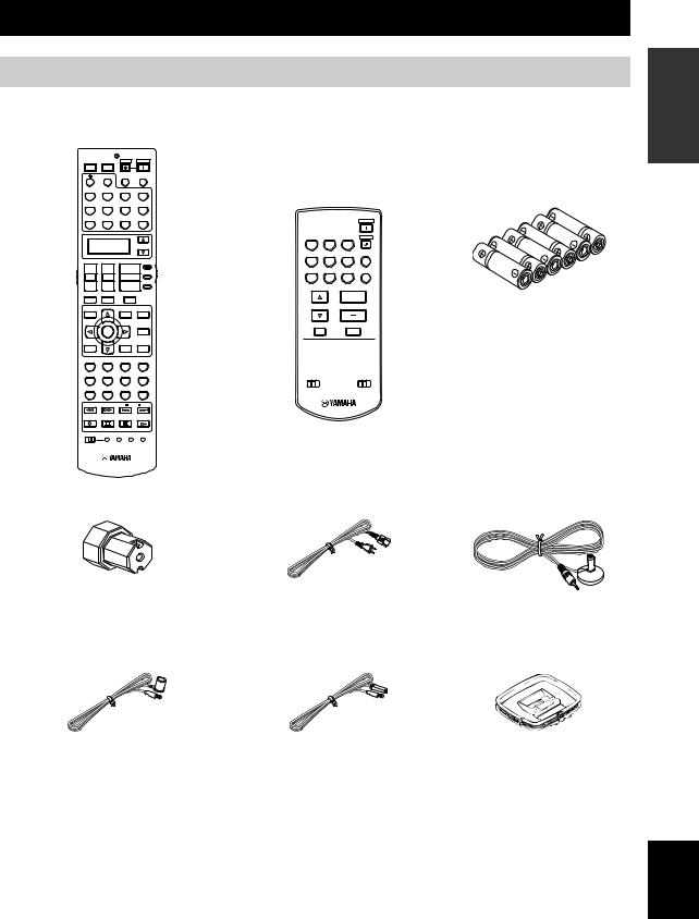
GETTING STARTED
Supplied accessories
Check that you received all of the following parts.
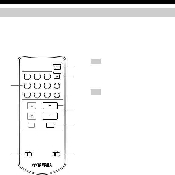
Remote control
POWER
TV
PHONO
V-AUX/DOCK
DTV
+
TV VOL
–
TV MUTE
LEVEL
TITLE
BAND
POWER |
STANDBY |
POWER |
AV |
|
|
NET/USB |
AUDIO SEL |
SLEEP |
TUNER |
CD |
MULTI CH IN |
CBL/SAT |
MD/TAPE |
CD-R |
VCR 1 |
DVR/VCR 2 |
DVD |
SELECT
AMP
++
|
|
SOURCE |
CH |
VOLUME |
|
– |
– |
TV |
|
||
TV INPUT |
MUTE |
|
PRESET/CH
SET MENU PURE DIRECT
MENU
SRCH MODE
|
|
ENTER |
|
|
|
AUDIO |
|
|
|
A/B/C/D/E |
|
||
|
|
|
|
|
STRAIGHT |
|
RETURN |
|
DISPLAY |
|
|
||
MEMORY |
|
|
|
|
EFFECT |
|
CLASSICAL |
LIVE/CLUB |
ENTERTAIN |
|
MOVIE |
||
1 |
|
2 |
3 |
|
4 |
|
STEREO |
SUR. DECODE |
SELECT |
EXTD SUR. |
|||
5 |
|
6 |
7 |
|
|
8 |
1 |
MEMORY 2 |
NIGHT |
ENHANCER |
|||
9 |
|
0 |
+10 |
|
ENT |
|
FREQ/TEXT |
EON |
MODE |
PTY SEEK |
START |
||
NET RADIO |
USB |
|
|
|
|
|
REC |
|
|
|
|
|
|
PC/MCX |
|
|
|
|
|
|
OFF |
ON |
MACRO LEARN |
CLEAR |
RENAME |
||
Zone 2/Zone 3 |
Batteries (6) |
||
remote control |
(AAA, LR03) |
||
|
|
POWER |
|
TUNER |
CD |
CD-R STANDBY |
|
DTV |
CBL/SAT MD/TAPE NET/USB |
|
|
VCR 1 DVR/VCR 2 |
DVD V-AUX/DOCK |
|
|
PRESET VOLUME
A/B/C/D/E
MUTE
ID1 ID2 |
ZONE 2 ZONE 3 |
Speaker terminal wrench |
Power cable |
Optimizer microphone |
Indoor FM antenna |
Indoor FM antenna |
AM loop antenna |
(U.S.A., Canada, China, Asia, General, |
(Europe, U.K. and Australia models) |
|
and Korea models) |
|
|
INTRODUCTION
English
5 En
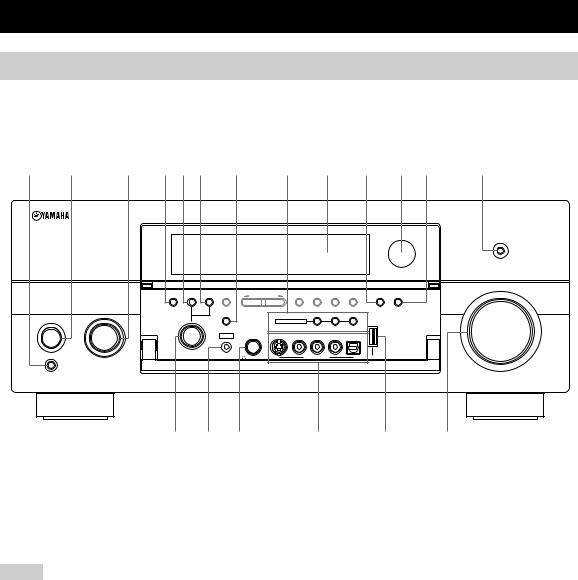
CONTROLS AND FUNCTIONS
Front panel
This section describes only the amplifier controls and functions of this unit. See the following pages for details about other control and functions.
• AM/FM tuning |
.......................................... see page 56 |
|
1 2 |
3 4 5 6 7 8 9 0 A B |
C |
PURE DIRECT
VOLUME
AUDIO |
TONE |
REC OUT/ |
|
|
PRESET/ |
FM/AM |
MEMORY |
TUNING |
ENHANCER |
|
SELECT |
CONTROL |
ZONE2 |
A/B/C/D/E |
PRESET/TUNING |
TUNING |
MAN'L/AUTO FM |
MODE |
NIGHT |
INPUT |
|
|
|
EDIT |
|
|
STRAIGHT |
|
|
|
ZONE ON/OFF |
ZONE CONTROLS |
|
|
|
|
|
|||
MAIN ZONE |
|
|
MULTI ZONE |
|
|
|
|
|
|
|
|
||
|
EFFECT |
|
|
|
ZONE 2 ZONE 3 |
|
ON/OFF |
YPAO |
SILENT CINEMA |
S VIDEO |
VIDEO |
L AUDIO R |
OPTICAL |
|
|
|
|
|
|
|
PROGRAM |
OPTIMIZER |
PHONES |
|
|
VIDEO AUX |
USB |
|
MIC |
|
|
|||
ON 
OFF 
MASTER
D E F
1 MASTER ON/OFF
Turns this unit on or off (see page 34).
2 MAIN ZONE ON/OFF
Turns on the main zone or sets it to the standby mode (see page 34).
Notes
•In the standby mode, this unit consumes a small amount of power in order to receive infrared signals from the remote control.
•When you turn on this unit, there will be a 4 to 5-second delay before this unit can reproduce sound.
•This button is operational only when MASTER ON/OFF is pressed inward to the ON position.
3 INPUT selector
Selects the desired input source (see page 40).
G H I
4 AUDIO SELECT
Toggles the priority for the type of audio input jack between “AUTO”, “HDMI”, “COAX/OPT” and “ANALOG” when one component is connected to two or more input jacks (see page 42).
5 TONE CONTROL
Adjusts the bass/treble balance of the front left, front right and center channels in conjunction with the PROGRAM selector (see page 52).
6 REC OUT/ZONE2
Selects the input source you want to direct to the audio/ video recorder and Zone 2 outputs independently of the input source you are listening to or watching in the main zone (see page 74).
7 STRAIGHT
Turns the sound field programs off or on. When the “STRAIGHT” mode is selected, 2-channel or multichannel input signals are output directly from their respective speakers without effect processing (see page 51).
6 En

8MULTI ZONE buttons
ZONE 2 ON/OFF
Turns on Zone 2 only or sets it to the standby mode (see page 122).
ZONE 3 ON/OFF
Turns on Zone 3 only or sets it to the standby mode (see page 122).
Note
These buttons are operational only when MASTER ON/OFF is pressed inward to the ON position.
ZONE CONTROLS
Switches the zone you want to control between the main zone, Zone 2 and Zone 3 (see page 122).
y
After you press ZONE CONTROLS, the indicator for the currently selected zone flashes in the front panel display for approximately 5 seconds. While the indicator is flashing, perform the desired operation.
9 Front panel display
Shows information about the operational status of this unit (see page 12).
0 ENHANCER
Turns on or off the Compressed Music Enhancer mode (see page 54).
A Remote control sensor
Receives signals from the remote control (see page 11).
B NIGHT
Turns on or off the night listening modes (see page 55).
C PURE DIRECT
Turns on or off the Pure Direct mode (see page 52).
CONTROLS AND FUNCTIONS
D PROGRAM selector
•Selects sound field programs (see page 46).
•Adjusts the bass/treble balance in conjunction with TONE CONTROL (see page 52).
E OPTIMIZER MIC jack
Use to connect and input audio signals from the supplied optimizer microphone in the “Auto Setup” procedure (see page 35).
F  PHONES jack
Outputs audio signals for private listening with headphones (see page 43).
G VIDEO AUX jacks
Input audio and video signals from a portable external source such as a game console or a video camera (see page 29).
y
To reproduce the source signals input at these jacks, select “V-AUX” as the input source.
Note
The audio signals input at the DOCK terminal on the rear panel take priority over the ones input at the VIDEO AUX jacks.
H USB port
Use to connect a USB memory device or a USB portable audio player (see page 72).
I VOLUME
Controls the output level of all audio channels.
y
This does not affect the AUDIO OUT (REC) level.
■ Opening and closing the front panel door
When you want to use the controls behind the front panel door, open the door by gently pressing on the lower part of the panel. Keep the door closed when not using these controls.
To open, press gently on the lower part of the panel.
INTRODUCTION
English
7 En
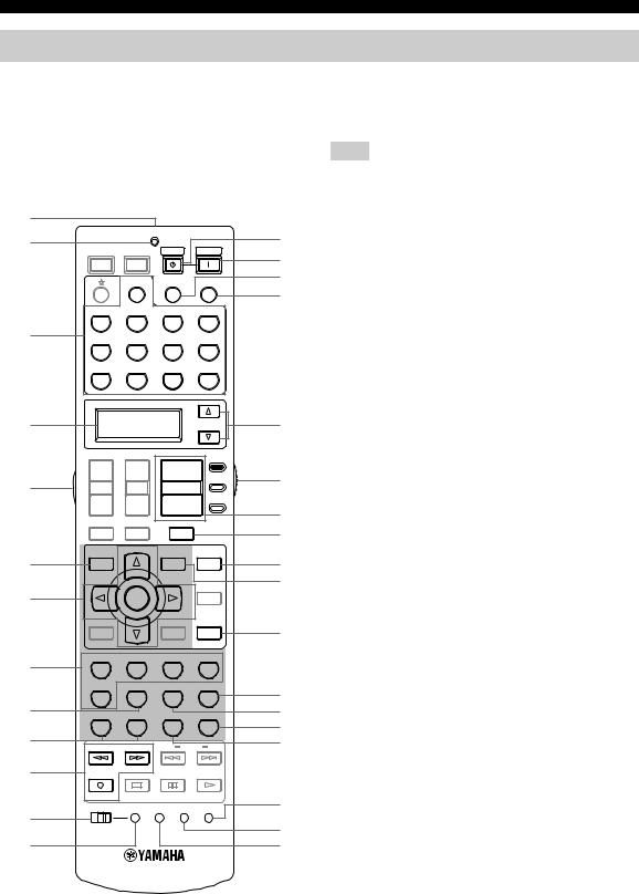
CONTROLS AND FUNCTIONS
Remote control
■ Remote control controls and functions
This section describes only the amplifier controls and functions of this unit. See the following pages for details about other control and functions.
• AM/FM tuning .......................................... |
see page 56 |
• Controlling a TV ..................................... |
see page 109 |
• Controlling other components ................. |
see page 110 |
• Controlling option components ............... |
see page 111 |
Note
The operation mode of the remote control buttons in the shaded area below depends on the operation mode selector position. Set the operation mode selector to AMP to control this unit.
1 |
|
|
|
|
2 |
|
STANDBY |
POWER |
D |
POWER |
POWER |
E |
||
TV |
AV |
|
|
|
|
NET/USB AUDIO SEL SLEEP |
F |
||
|
|
|||
|
|
|
|
G |
|
PHONO |
3 |
V-AUX/DOCK |
|
DTV |
4 |
|
|
+ |
5 |
TV VOL |
|
– |
|
TV MUTE |
6 |
LEVEL |
TITLE |
|
|
BAND |
7 |
|
TUNER |
CD |
MULTI CH IN |
CBL/SAT |
MD/TAPE |
CD-R |
VCR 1 |
DVR/VCR 2 |
DVD |
SELECT |
H |
AMP
++
|
|
SOURCE |
I |
CH |
VOLUME |
|
|
– |
– |
TV |
|
|
J |
||
|
|
|
|
TV INPUT |
MUTE |
|
K |
PRESET/CH |
SET MENU |
PURE DIRECT |
|
|
L |
||
|
MENU |
|
|
|
SRCH MODE |
|
M |
|
|
|
|
ENTER |
|
AUDIO |
|
|
|
|
|
A/B/C/D/E |
|
|
|
|
|
|
|
STRAIGHT |
N |
|
RETURN |
|
|
DISPLAY |
|
|
|
MEMORY |
|
|
|
EFFECT |
|
|
CLASSICAL |
LIVE/CLUB |
ENTERTAIN |
MOVIE |
|
|
8 |
1 |
|
2 |
3 |
4 |
|
|
STEREO |
SUR. DECODE |
SELECT |
EXTD SUR. |
O |
|
|
5 |
|
6 |
7 |
8 |
|
9 |
1 MEMORY |
2 |
NIGHT |
ENHANCER |
P |
|
0 |
9 |
|
0 |
+10 |
ENT |
Q |
FREQ/TEXT |
|
EON |
MODE PTY SEEK START |
R |
||
A |
NET RADIO |
|
USB |
|
|
|
REC |
|
|
|
|
|
|
PC/MCX |
|
OFF ON MACRO LEARN CLEAR RENAME |
S |
B |
t |
|
|
C |
U |
1 Infrared window
Outputs infrared control signals. Aim this window at the component you want to operate (see page 11).
2 TRANSMIT indicator
Flashes while the remote control is sending infrared signals.
3 Input selector buttons
Select the input source you want to control.
y
The selected input source name appears in the display window on the remote control showing which source is currently operational.
4 Display window
Shows the name of the selected input source that you can control.
5 LIGHT
Lights up the remote control buttons and the display window.
6 LEVEL
Selects the speaker channel to be adjusted and sets the output level (see page 53).
7 Cursor buttons k / n / l / h, ENTER
Move the items or cursor and adjust the parameters in the GUI screens or front panel display.
8Sound field program selector buttons
Select sound field programs (see page 46).
9SUR. DECODE
Activates decoders to play back 2-channel sources in surround (see page 75).
0 MEMORY 1/2
Recalls “MEMORY 1” or “MEMORY 2” of “System Memory” (see page 106).
A Network and USB input selector buttons
Select the sub input source of NET/USB (see page 69).
PC/MCX
Selects a PC server or YAMAHA MCX-2000 as the sub input source of NET/USB.
8 En
NET RADIO
Selects the Internet radio as the sub input source of NET/USB.
USB
Selects a USB memory device or a USB portable audio player as the sub input source of NET/USB.
Notes
•Press NET/USB to select “NET/USB” as the input source before you press any of the network and USB input selector buttons stated above to select the corresponding sub input source of NET/USB.
•When you press any of the network and USB input selector buttons, the contents previously played for the corresponding sub input source of NET/USB is automatically played.
B MACRO ON/OFF
Turns on or off the macro function (see page 115).
C MACRO
Programs a series of operations to be controlled with a single button (see page 115).
D STANDBY
Sets the main zone to the standby mode (see page 34).
Note
This button is operational only when MASTER ON/OFF on the front panel is pressed inward to the ON position.
E POWER
Turns on the main zone (see page 34).
Note
This button is operational only when MASTER ON/OFF on the front panel is pressed inward to the ON position.
F AUDIO SEL
Toggles the priority for the type of audio input jack between “AUTO”, “HDMI”, “COAX/OPT” and “ANALOG” when one component is connected to two or more input jacks (see page 42).
G SLEEP
Sets the sleep timer (see page 45).
H SELECT k / n
Selects another input source that you can control independently of the input source selected with the input selector buttons.
I Operation mode selector
Selects the operation mode of the remote control buttons in the shaded area.
AMP
Operates the amplifier function of this unit.
CONTROLS AND FUNCTIONS
SOURCE
Operates the component selected with an input selector button (see page 110).
TV
Operates the TV assigned to either DTV or PHONO (see page 109).
Notes
•To set the remote control codes for other components, see page 111.
•When you set the remote control codes for both DTV and PHONO (see page 111), priority is given to the one set for DTV.
J VOLUME +/–
Increases or decreases the volume level.
K MUTE
Mutes the audio output. Press again to restore the audio output to the previous volume level (see page 43).
L PURE DIRECT
Turns on or off the pure direct mode (see page 52).
M SET MENU
Activates the GUI screen (see page 44).
N STRAIGHT
Turns the sound field programs off or on. When the “STRAIGHT” mode is selected, 2-channel or multichannel input signals are output directly from their respective speakers without effect processing (see page 51).
O EXTD SUR.
Switches between 5.1 and 6.1/7.1-channel playback of multi-channel sources (see page 75).
P SELECT
Selects decoders for 2-channel sources (see pages 75 and 76).
Q ENHANCER
Turns on or off the Compressed Music Enhancer mode (see page 54).
R NIGHT
Turns on or off the night listening modes (see page 55).
S RENAME
Changes the name of the input source in the display window (see page 114).
T CLEAR
Clears remote control functions acquired from the learn, macro and/or rename features (see page 118).
U LEARN
Programs remote control codes of functions from other remote controls (see page 113).
INTRODUCTION
English
9 En
CONTROLS AND FUNCTIONS
Zone 2/Zone 3 remote control
This section describes the function of each control on the Zone 2/Zone 3 remote control used to control the amplifier functions of Zone 2 or Zone 3.
See the following pages for details about other controls and functions.
• AM/FM tuning ........................................ |
|
|
see page 56 |
|
|
|
POWER |
|
|
|
3 |
TUNER |
CD |
CD-R |
STANDBY |
|
|
|
4 |
DTV |
CBL/SAT MD/TAPE |
NET/USB |
|
1 |
|
|
|
VCR 1 DVR/VCR 2 |
DVD |
V-AUX/DOCK |
|
PRESET |
VOLUME |
5 |
A/B/C/D/E |
|
|
|
MUTE |
6 |
ID1 ID2 |
ZONE 2 ZONE 3 |
2 |
7 |
1 Input selector buttons
Select the desired input source of Zone 2 or Zone 3.
2 ID1/ID2 switch
Switches the remote control ID between ID1 and ID2 (see page 112).
3 POWER
Turns on Zone 2 or Zone 3.
Note
This button is operational only when MASTER ON/OFF on the front panel is pressed inward to the ON position.
4 STANDBY
Sets Zone 2 or Zone 3 to the standby mode.
Note
This button is operational only when MASTER ON/OFF on the front panel is pressed inward to the ON position.
5 VOLUME +/–
Increases or decreases the volume level of Zone 2 or Zone 3.
6 MUTE
Mutes the sound of Zone 2 or Zone 3. Press again to restore the audio output to the previous volume level.
7 ZONE 2/ZONE 3 switch
Switches between the operation mode of Zone 2 and that of Zone 3.
10 En
Preparing the remote control
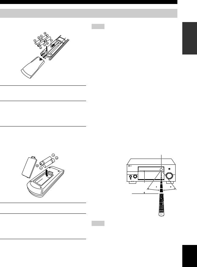
■ Installing batteries in the remote control
1
3
1Press the  part and slide the battery compartment cover off.
2Insert the four supplied batteries (AAA, LR03) according to the polarity markings (+ and –) on the inside of the battery compartment.
3Slide the cover back until it snaps into place.
■Installing batteries in the Zone 2/Zone 3 remote control
1
 3
3
2
1Take off the battery compartment cover.
2Insert the two supplied batteries (AAA, LR03) according to the polarity markings
(+ and –) on the inside of the battery compartment.
3Snap the battery compartment cover back into place.
CONTROLS AND FUNCTIONS
Notes
•Change all of the batteries if you notice the following conditions:
–the operation range of the remote control decreases.
–the TRANSMIT indicator does not flash or its light becomes dim.
•Do not use old batteries together with new ones.
•Do not use different types of batteries (such as alkaline and manganese batteries) together. Read the packaging carefully as these different types of batteries may have the same shape and color.
•We recommend using alkaline batteries.
•If the batteries have leaked, dispose of them immediately. Avoid touching the leaked material or letting it come into contact with clothing, etc. Clean the battery compartment thoroughly before installing new batteries.
•Do not throw away batteries with general house waste; dispose of them correctly in accordance with your local regulations.
•If the remote control is without batteries for more than 2 minutes, or if exhausted batteries remain in the remote control, the contents of the memory may be cleared. When the memory is cleared, insert new batteries, set up the remote control code and program any acquired functions that may have been cleared.
■ Using the remote control
The remote control transmits a directional infrared ray. Be sure to aim the remote control directly at the remote control sensor on this unit during operation.
Remote control sensor
Approximately 6 m |
30 |
30 |
|
Notes
•Do not spill water or other liquids on the remote control.
•Do not drop the remote control.
•Do not leave or store the remote control in the following types of conditions:
–places of high humidity, such as near a bath
–places of high temperatures, such as near a heater or stove
–places of extremely low temperatures
–dusty places
INTRODUCTION
English
11 En
CONTROLS AND FUNCTIONS
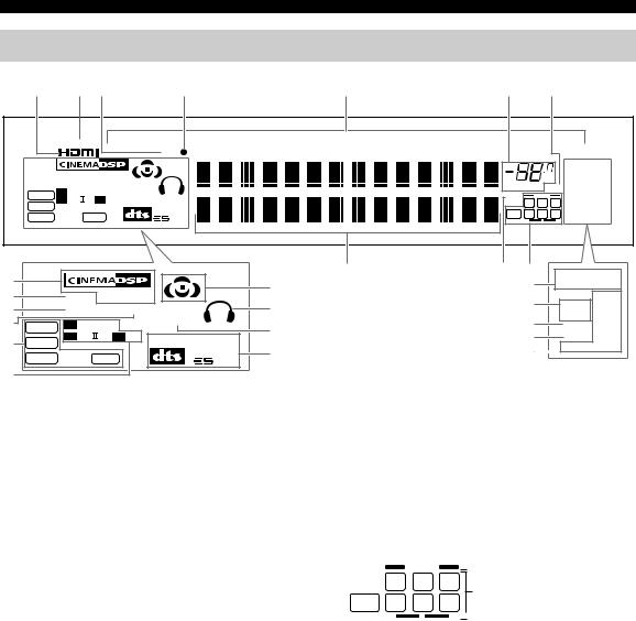
Front panel display
1 |
2 3 |
4 |
5 |
6 |
7 |
RECOUT  NET/USB
  V-AUX
V-AUX 
DOCK
DVR/VCR 2  VCR 1
VCR 1  CBL/SAT
  DTV
DTV  DVD
DVD 
MD/TAPE
 CD-R
CD-R
 CD
CD
 PHONO
PHONO
 MULTI
MULTI
CH 
TUNER
|
|
|
|
|
|
|
|
|
|
|
TUNED STEREO |
|
|
|
VIRTUAL HiFi DSP |
|
|
|
|
|
dB |
AUTO MEMORY |
|||
|
|
|
|
|
|
|
|
PS |
||||
|
|
YPAO ENHANCER SILENT |
|
|
|
|
|
|
||||
|
|
|
|
|
VOLUME MUTE |
ZONE2 PTY |
||||||
|
|
DIGITAL |
CINEMA |
|
|
|||||||
|
DSD |
|
|
96/24 |
|
ZONE3 |
RT |
|||||
|
PL x |
EX |
MATRIX |
DISCRETE |
|
|
|
|||||
|
PCM |
|
|
|
L C R |
NIGHT |
CT |
|||||
|
|
|
|
96 |
|
|
LFE |
SL |
SB SR |
SLEEP |
EON |
|
|
WMA |
MP3 |
|
|
|
|||||||
|
|
24 |
|
|
PTY HOLD |
|||||||
|
|
|
|
|
|
|
||||||
A |
|
|
|
|
|
|
8 |
9 0 |
TUNED STEREO |
|||
|
|
|
|
|
|
G |
|
K |
AUTO MEMORY |
|||
|
|
|
|
|
|
|
|
|||||
B |
|
VIRTUAL HiFi DSP |
|
|
|
|
L |
|
|
PS |
||
C |
|
YPAO ENHANCER |
SILENT |
|
H |
|
|
ZONE2 PTY |
||||
|
|
|
|
|
ZONE3 |
RT |
||||||
D |
|
DIGITAL |
|
CINEMA |
|
|
|
M |
|
|||
DSD |
|
|
I |
|
|
NIGHT |
CT |
|||||
|
|
|
|
|
||||||||
|
|
PL |
x |
EX |
MATRIX |
DISCRETE |
|
N |
|
SLEEP |
EON |
|
E |
PCM |
|
|
|
||||||||
|
|
|
|
96 |
J |
|
O |
|
PTY HOLD |
|||
|
WMA |
|
MP3 |
|
|
|
|
|
|
|||
|
|
|
|
24 |
|
|
|
|
|
|
||
F |
|
|
|
|
|
|
O........ U.K. and Europe models only |
|
|
|
|
|
|
|
|
|
|
|
|
|
|
|
|
||
1 HDMI indicator
Lights up when the signal of the selected input source is input at HDMI IN 1, HDMI IN 2 or HDMI IN 3 jacks (see page 21).
2 RECOUT indicator
Lights up when this unit is in the recording input source selecting mode (see page 74).
3 DOCK indicator
Lights up when you station your iPod in a YAMAHA iPod universal dock (such as the YDS-10, sold separately) connected to the DOCK terminal of this unit
(see page 29).
4 Battery charge indicator
Lights up when this unit charges the battery of the stationed iPod in the standby mode of this unit (see page 66).
5 Input source indicators
The corresponding cursor lights up to show the currently selected input source.
6VOLUME level indicator
Indicates the current volume level.
7MUTE indicator
Flashes while the MUTE function is on (see page 43).
8 Multi-information display
Shows the name of the current sound field program and other information when adjusting or changing settings.
9 96/24 indicator
Lights up when a DTS 96/24 signal is input to this unit.
0 Input channel and speaker indicators
 Presence speaker indicators
L C R
Input channel indicators
LFE SL SB SR
 Surround back speaker indicators
Input channel indicators
Indicate the channel components of the current digital input signal.
Presence and surround back speaker indicators
Light up according to the number of presence and surround back speakers set for “Presence” (see page 97) and “Surround Back” (see page 97) in “Speaker Set” when “Test Tone” in “Basic” is set to “ON” (see page 96).
y
You can make settings for the presence and surround back speakers automatically by running “Auto Setup” (see page 35) or manually by adjusting settings for “Presence” (see page 97) and “Surround Back” (see page 97) in “Speaker Set”.
12 En

A DSP indicators
The respective indicator lights up when any of the DSP sound field programs are selected.
CINEMA DSP indicator
Lights up when you select a CINEMA DSP sound field program (see page 47).
HiFi DSP indicator
Lights up when you select a HiFi DSP sound field program (see page 47).
B VIRTUAL indicator
Lights up when Virtual CINEMA DSP is active (see page 51).
C YPAO indicator
Lights up when you run “Auto Setup” and when the speaker settings set in “Auto Setup” are used without any modifications (see page 35).
D ENHANCER indicator
Lights up when the Compressed Music Enhancer mode is turned on (see page 54).
E Signal format indicators
The respective indicator lights up when this unit is reproducing DSD (Direct Stream Digital), PCM (Pulse Code Modulation), WMA (Windows Media Audio), WAV (RIFF Wave Form Audio) or MP3 (MPEG-1 Audio Layer- 3) audio signals.
F Dolby decoder indicators
The respective indicator lights up when any of the Dolby decoders of this unit function.
G Sound field indicators
Light up to indicate the active DSP sound fields.
Presence DSP sound field
|
Listening position |
Surround left |
Surround right |
DSP sound field |
DSP sound field |
Surround back DSP sound field
CONTROLS AND FUNCTIONS
H Headphones indicator
Lights up when headphones are connected (see page 43).
I SILENT CINEMA indicator
Lights up when headphones are connected and a sound field program is selected (see page 51).
J DTS decoder indicators
The respective indicator lights up when any of the DTS decoders of this unit function.
K Tuner indicators
Lights up when this unit is in the FM or AM tuning mode.
TUNED indicator
Lights up when this unit is tuned into a station (see page 56).
STEREO indicator
Lights up when this unit is receiving a strong signal for an FM stereo broadcast while the AUTO indicator is lit (see page 56).
AUTO indicator
Lights up when this unit is in the automatic tuning mode (see page 56).
MEMORY indicator
Flashes to show that a station can be stored (see page 59).
L ZONE2/ZONE3 indicators
Lights up when Zone 2 or Zone 3 is turned on (see page 122).
M NIGHT indicator
Lights up when you select a night listening mode (see page 55).
N SLEEP indicator
Lights up while the sleep timer is on (see page 45).
ORadio Data System indicators (U.K. and Europe models only)
PS, PTY, RT and CT
Light up according to the selected Radio Data System display mode.
EON
Lights up when the EON data service is being received.
PTY HOLD
Lights up while searching for the Radio Data System stations in the PTY SEEK mode.
INTRODUCTION
English
13 En
CONTROLS AND FUNCTIONS
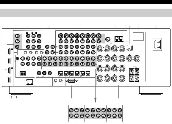
Rear panel
1 |
2 |
3 |
4 |
5 |
6 |
7 |
|
COMPONENTVIDEO |
DVD |
DTV |
CBL/SAT |
VIDEO |
|
|
DVR/VCR 2 OUT |
MONITOR OUT |
ANTENNA |
|
|
||||
MONITOR OUT |
A DVD |
B DTV C CBL/SAT |
IN |
VCR 1 |
OUT |
IN |
|
|
|
|
||||||
Y |
Y |
|
|
|
|
|
|
|
|
|
|
FM |
GND |
AM |
|
|
|
|
|
|
|
|
|
|
|
|
|
|
|
|
|
||
|
|
|
|
|
|
|
|
|
|
|
|
SVIDEO |
|
|
|
|
PB |
PB |
|
|
|
|
|
|
|
|
|
|
|
|
|
|
|
|
|
IN |
OUT |
|
|
|
|
|
|
|
|
VIDEO |
SP1 |
SPEAKERS |
|
|
|
|
|
|
|
|
|
|
|
|
+ |
+ |
|
|
|||
|
|
(PLAY) |
(REC) |
|
|
|
|
|
|
|
R |
PRESENCE |
L |
WRENCH |
||
HDMI |
|
|
|
|
|
|
|
|
|
|
||||||
PR |
MD/ |
L |
|
|
|
|
|
|
|
|
|
|
|
|
||
PR |
|
|
|
|
|
|
|
|
|
|
|
|
HOLDER |
|||
|
|
TAPE |
|
|
|
|
|
|
|
|
|
|
|
|
|
|
IN3 |
|
|
|
|
|
|
|
|
|
|
|
|
|
|
|
|
|
|
|
REMOTE |
IN |
OUT |
IN |
OUT |
|
|
|
|
|
|
|
|
|
|
|
|
|
||
|
|
|
|
|
|
|
|
|
|
|
|
|
|
|
|
|
|
||
CBL/ |
|
|
1 |
|
2 |
|
|
R |
|
|
|
|
|
|
|
SURROUND BACK/ |
|
CENTER |
|
|
|
|
|
|
|
|
|
|
|
|
|
|
|
+ |
+ |
+ |
|||
SAT |
|
|
|
|
|
|
|
|
|
|
|
|
|
|
|||||
|
|
|
|
|
|
|
|
|
|
|
|
|
|
|
BI-AMP |
|
|||
GND |
PHONO |
|
CD |
CD-R |
|
CENTER |
FRONT(6CH) SURROUND |
CENTER |
FRONT |
SURROUND SINGLE(SB) |
ZONE 2 |
ZONE 3 |
ZONE |
|
|
SINGLE |
|
|
|
|
|
VIDEO |
|
|
|
|
|
||||||||||||
IN2 |
L |
|
|
|
|
|
|
|
|
|
|
|
|
|
|
|
|
|
|
DTV |
R |
|
|
|
|
|
|
|
|
|
|
|
|
|
+ |
SURROUND |
+ |
|
|
|
|
|
|
|
|
|
|
|
|
|
|
|
R |
L |
|
||||
|
|
|
|
|
|
|
|
|
|
|
|
|
|
|
|||||
|
|
|
IN(PLAY) OUT(REC) |
|
SUB |
SB(8CH) |
SUB |
|
SUR.BACK/ |
|
|
|
|
|
|
|
R SP2 L |
||
IN1 |
|
|
AUDIO |
|
|
WOOFER |
WOOFER |
|
PRESENCE |
|
|
|
|
|
|
|
|||
|
|
|
|
|
MULTI CH INPUT |
|
PRE OUT |
|
ZONE OUT |
|
|
|
|
|
|
||||
DOCK |
|
|
|
|
|
|
|
|
|
|
|
|
|||||||
|
|
|
|
|
|
DIGITAL INPUT |
|
|
DIGITAL OUTPUT |
|
|
|
|
|
|||||
DVD |
|
|
|
|
|
|
|
|
|
|
|
|
|
|
|
|
|
+ |
|
|
|
|
|
|
|
|
|
|
|
|
|
|
|
+ |
FRONT |
+ |
|
|
|
|
|
|
|
|
|
|
|
COAXIAL |
|
|
|
|
|
OPTICAL R |
L |
|
|||
OUT |
|
|
|
1 |
CD |
2 |
DVD |
3 VCR2DVR/ |
4 CD |
5 DVD |
6 DTV 7 CBL/SAT |
8 TAPEMD/ |
9 CD-R |
|
|
|
|
|
|
|
|
|
NETWORK |
|
|
|
|
|
|
|
|
|
|
|
|
|
|
|
|
|
|
|
|
|
|
|
|
1 |
2 |
|
|
|
|
|
|
|
|
|
|
|
|
|
|
|
|
|
|
CONTROL OUT |
|
RS-232C |
|
|
|
|
|
|
|
|
|
8 9 0 A |
B |
C |
D |
E |
|
|
|
|
F |
|
|
|
|
CENTER |
FRONT(6CH) SURROUND |
CENTER |
FRONT SURROUND SINGLE(SB) |
ZONE 2 ZONE 3 |
ZONE |
|
|
|
|
|
|
|
|
|
VIDEO |
|
|
|
|
SUB |
SB(8CH) |
SUB |
SUR.BACK/ |
|
|
|
|
|
|
WOOFER |
WOOFER |
PRESENCE |
ZONE OUT |
||
|
|
|
|
MULTI CH INPUT |
|
PRE OUT |
|||
AC IN
AC OUTLETS
G
1 COMPONENT VIDEO jacks
See pages 23 and 24 for connection information.
20 Audio component jacks
See page 26 for connection information.
3 Video component jacks
See pages 23 and 24 for connection information.
4 ANTENNA terminals
See page 31 for connection information.
5 WRENCH HOLDER
Use to hook the supplied speaker terminal wrench when not in use (see page 18).
6VOLTAGE SELECTOR
(Asia and General models only)
See page 32 for details.
7 AC IN/OUTLET(S)
See page 32 for connection information.
8 HDMI connectors
See page 21 for connection information.
9 REMOTE jacks
See page 121 for details.
A DOCK terminal
See page 29 for connection information.
H I
B NETWORK port
Use to connect a network cable for network connections. See page 30 for connection information.
CDIGITAL INPUT/OUTPUT jacks
See page 24 for connection information.
DCONTROL OUT jack
This is a control expansion terminal for custom installation.
E RS-232C terminal
This is a control expansion terminal for factory use only. Consult your dealer for details.
F Speaker terminals
See page 16 for connection information.
G MULTI CH INPUT jacks
See page 28 for connection information.
H PRE OUT jacks
See page 27 for connection information.
I ZONE OUT jacks
See page 121 for connection information.
14 En
CONNECTIONS
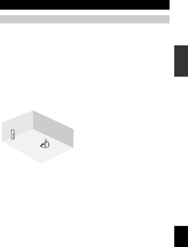
Placing speakers
The speaker layout below shows the speaker setting we recommend. You can use it to enjoy CINEMA DSP and multi-channel audio sources.
PL |
PR |
|
C |
FL |
FR |
30˚
SL |
|
SR |
|
|
60˚ |
SL |
80˚ |
SR |
|
SBL |
SBR |
30 cm or more
|
PR |
PL |
FR |
|
|
FL |
SW |
SR |
|
C |
SBR |
|
SBL |
|
SL |
1.8 m
0.5 to 1 m |
0.5 to 1 m |
PL |
FL
C |
PR |

 FR
FR
1.8 m
Front left and right speakers (FL and FR)
The front speakers are used for the main source sound plus effect sounds. Place these speakers at an equal distance from the ideal listening position. The distance of each speaker from each side of the video monitor should be the same.
Center speaker (C)
The center speaker is for the center channel sounds (dialog, vocals, etc.). If for some reason it is not practical to use a center speaker, you can do without it. Best results, however, are obtained with the full system. Place the center speaker centrally between the front speakers and as close to the monitor as possible, such as directly over or under it.
Surround left and right speakers (SL and SR)
The surround speakers are used for effect and surround sounds. Place these speakers behind your listening position, facing slightly inwards, about 1.8 m above the floor.
Surround back left and right speakers (SBL and SBR)
The surround back speakers supplement the surround speakers and provide more realistic front-to-back transitions. Place these speakers directly behind the listening position and at the same height as the surround speakers. They should be positioned at least 30 cm apart. Ideally, they should be positioned at the same width as that of the front speakers.
Presence left and right speakers (PL and PR)
The presence speakers supplement the sound from the front speakers with extra ambient effects produced by CINEMA DSP (see page 144). These effects include sounds that filmmakers intend to locate a little farther back behind the screen in order to create more theater-like ambience. Place these speakers at the front of the room about 0.5 to 1 m outside the front speakers, facing slightly inward, and about 1.8 m above the floor.
Subwoofer (SW)
The use of a subwoofer with a built-in amplifier, such as the YAMAHA Active Servo Processing Subwoofer System, is effective not only for reinforcing bass frequencies from any or all channels, but also for high fidelity sound reproduction of the LFE (low-frequency effect) channel included in Dolby Digital and DTS sources. The position of the subwoofer is not so critical, because low bass sounds are not highly directional. But it is better to place the subwoofer near the front speakers. Turn it slightly toward the center of the room to reduce wall reflections.
PREPARATION
English
15 En
CONNECTIONS
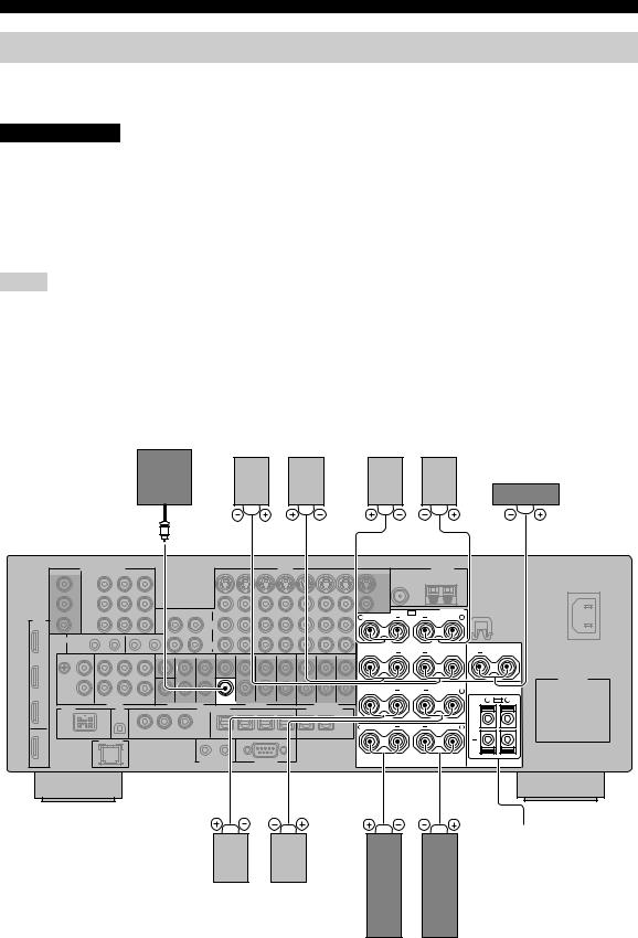
Connecting speakers
Be sure to connect the left channel (L), right channel (R), “+” (red) and “–” (black) properly. If the connections are faulty, no sound will be heard from the speakers, and if the polarity of the speaker connections is incorrect, the sound will be unnatural and lack bass.
CAUTION
•Before connecting the speakers, make sure that this unit is turned off (see page 34).
•Do not let the bare speaker wires touch each other or do not let them touch any metal part of this unit. This could damage this unit and/or speakers.
•Use magnetically shielded speakers. If this type of speaker still creates interference with the monitor, place the speakers away from the monitor.
•If you are to use 6 ohm speakers, be sure to set “SPEAKER IMP.” to “6ΩMIN” before using this unit
(see page 33). 4 ohm speakers can be also used as the front speakers (see page 126).
Notes
•A speaker cord is actually a pair of insulated cables running side by side. Cables are colored or shaped differently, perhaps with a stripe, groove or ridge. Connect the striped (grooved, etc.) cable to the “+” (red) terminals of this unit and your speaker. Connect the plain cable to the “–” (black) terminals.
•The low-frequency signals of other speakers set to “Small” or to “None” in “Speaker Set” (see pages 96 and 97) are directed to the speakers selected in “Bass Out” (see page 98).
•You can connect both surround back and presence speakers to this unit, however they do not output sound simultaneously. You can set to prioritize either set of speakers using the “PR/SB Priority” parameter in “Speaker Set” (see page 98).
•You can use the PRESENCE terminals to connect the Zone 2 or Zone 3 speakers as well as the presence speakers (see page 121).
Subwoofer |
Surround back speakers |
Presence speakers |
||
|
Left |
Right |
Right |
Left |
Center speaker
SUB |
WOOFER |
PRE OUT |
R |
+ |
|
+ |
R |
+ |
R |
+ |
SP1 |
SPEAKERS |
|
+ |
|
|
PRESENCE |
L |
|
SURROUND BACK/ |
+ |
|
BI-AMP |
|
|
|
SINGLE |
|
SURROUND |
+ |
L |
FRONT |
+ |
L |
CENTER +
R SP2 L
+
Zone 2 or Zone 3 speakers
(see page 121)
Right Left
Surround speakers
Right Left
Front speakers
16 En
FRONT terminals
Connect front left and right speakers to these terminals.
CENTER terminals
Connect a center speaker to these terminals.
SURROUND terminals
Connect surround left and right speakers to these terminals.
SURROUND BACK terminals
Connect surround back left and right speakers to these terminals.
Note
When you use a surround back speaker, connect the speaker to the left SURROUND BACK terminal (SINGLE).
PRESENCE terminals
Connect presence left and right speakers to these terminals.
SUBWOOFER jack
Connect a subwoofer with a built-in amplifier (such as the YAMAHA Active Servo Processing Subwoofer System) to this jack.
CONNECTIONS
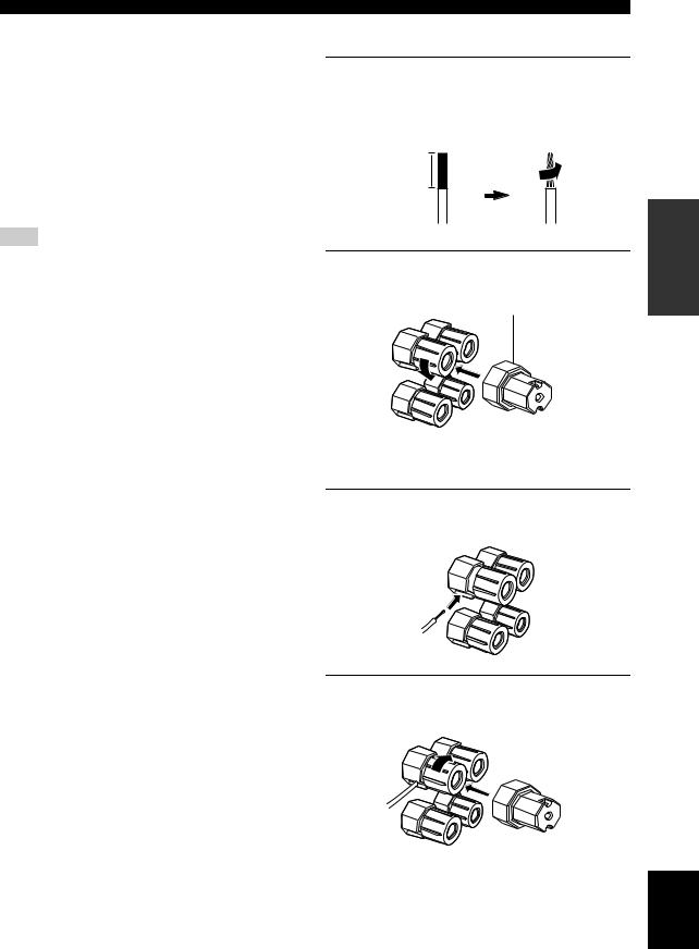
■ Connecting the speaker cable
1Remove approximately 10 mm of insulation from the end of each speaker cable and then twist the exposed wires of the cable together to prevent short circuits.
10 mm
2Loosen the knob using the supplied speaker terminal wrench.
Speaker terminal wrench
Red: positive (+)
Black: negative (–)
3Insert one bare wire into the hole on the side of each terminal.
4Tighten the knob to secure the wire using the supplied speaker terminal wrench.
PREPARATION
English
17 En
CONNECTIONS
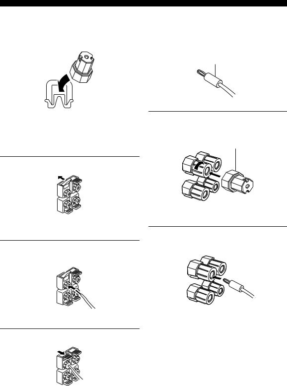
|
■ Connecting the banana plug |
5 Hook the speaker terminal wrench onto the |
(except U.K., Europe, Asia and Korea |
WRENCH HOLDER on the rear panel of this |
models) |
unit when not in use. |
The banana plug is a single-pole electrical connector |
|
widely used to terminate speaker cables. |
|
Banana plug |
■ Connecting to the SP2 speaker terminals
Connect Zone 2 or Zone 3 speakers to these terminals (see page 121).
1Tighten the knob using the supplied speaker terminal wrench.
Speaker terminal wrench
1 Open the tab.
Red: positive (+)
Black: negative (–)
Red: positive (+)
Black: negative (–)
2 Insert the banana plug connector into the end of the corresponding terminal.
2Insert one bare wire into the hole on the terminal.
3 Close the tab to secure the wire.
y
You can also use the banana plug with the SP2 speaker terminals. Open the tab and then insert one banana plug into the hole on the terminal. Do not close the tab after connecting the banana plug.
18 En
Using bi-amplification connections
Some of the speakers have speaker wire connections that allow bi-amplification to enhance the performance of the speaker system. This unit allows you to make biamplification connection to one speaker system. Check if your speakers support bi-amplification. As these speakers are shipped to you, you will note shorting bars or bridges, one connecting the two red input terminals and the other connecting the two black input terminals. Remove these shorting bars or bridges only if you plan to bi-amplify your speakers.
■ Conventional connection
If you want to connect your speakers as traditional loudspeakers using the conventional connection method, connect your speakers using the regular left and right speaker wire connections and ignore the second set of terminals.
This unit
R + |
FRONT |
+ L |
Right |
Left |
Front speakers
Shorting bars |
Shorting bars |
or bridges |
or bridges |
CONNECTIONS
■ Bi-amplification connection
To make the bi-amplification connections, use the FRONT and SURROUND BACK terminals as shown below. To activate the bi-amplification connections, set “BI-AMP” to “ON” in “ADVANCED SETUP” (see page 127).
This unit
+ |
SURROUND BACK/ |
+ |
BI-AMP |
||
|
|
SINGLE |
R + |
FRONT |
+ L |
Right |
Left |
Front speakers
Note
Remove the shorting bars or bridges to separate the LPF (low pass filter) and HPF (high pass filter) crossovers.
PREPARATION
English
19 En
CONNECTIONS
Information on jacks and cable plugs
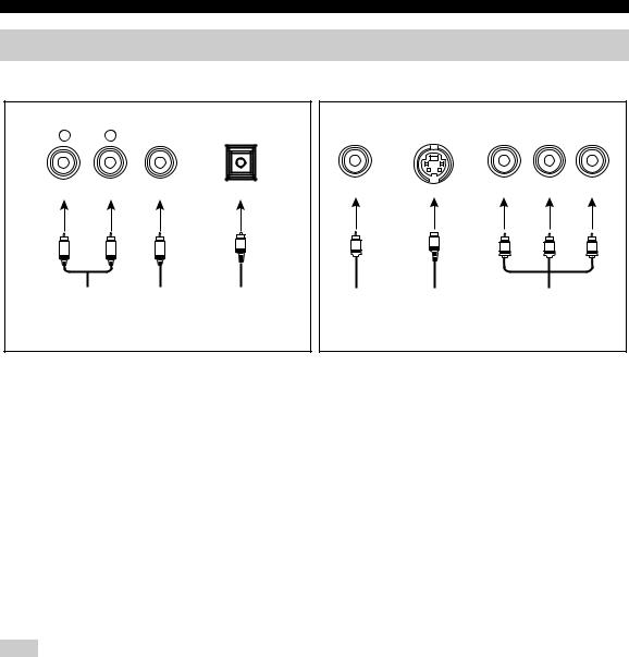
Audio jacks and cable plugs
AUDIO |
DIGITAL |
DIGITAL |
|
L |
R |
COAXIAL |
OPTICAL |
(White) |
(Red) |
(Orange) |
|
L |
R |
C |
O |
|
|||
Left and right |
Coaxial |
Optical |
|
analog audio |
digital audio |
digital |
|
cable plugs |
cable plug |
audio cable |
|
|
|
|
plug |
Video jacks and cable plugs
|
|
COMPONENT VIDEO |
||
VIDEO |
S VIDEO |
Y |
PB |
PR |
(Yellow) |
|
(Green) |
(Blue) |
(Red) |
V |
S |
Y |
PB |
PR |
|
||||
Composite |
S-video |
Component |
||
video cable |
cable plug |
|
video cable |
|
plug |
|
|
plugs |
|
■ Audio jacks
This unit has three types of audio jacks. Connection depends on the availability of audio jacks on your other components.
AUDIO jacks
For conventional analog audio signals transmitted via left and right analog audio cables. Connect red plugs to the right jacks and white plugs to the left jacks.
DIGITAL COAXIAL jacks
For digital audio signals transmitted via coaxial digital audio cables.
DIGITAL OPTICAL jacks
For digital audio signals transmitted via optical digital audio cables.
Note
You can use the digital jacks to input PCM, Dolby Digital and DTS bitstreams. When you connect components to both the COAXIAL and OPTICAL jacks, priority is given to the signals input at the COAXIAL jack. All digital input jacks are compatible with 96-kHz sampling digital signals.
■ Video jacks
This unit has three types of video jacks. Connection depends on the availability of input jacks on your video monitor.
VIDEO jacks
For conventional composite video signals transmitted via composite video cables.
S VIDEO jacks
For S-video signals, separated into the luminance (Y) and chrominance (C) video signals transmitted on separate wires of S-video cables.
COMPONENT VIDEO jacks
For component video signals, separated into the luminance (Y) and chrominance (PB, PR) video signals transmitted on separate wires of component video cables.
y
This unit equips the video conversion function. See pages 22 and 93 for details.
20 En
CONNECTIONS
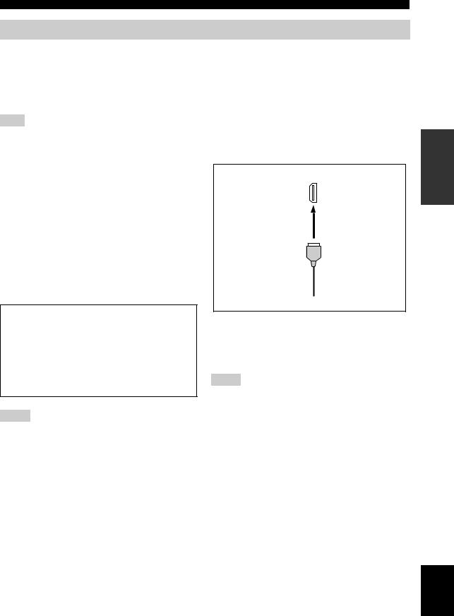
Information on HDMI
This unit has the HDMI IN 1, HDMI IN 2, HDMI IN 3 and HDMI OUT jacks for digital audio and video signal input/ output. Connect the HDMI IN 1, HDMI IN 2 or HDMI IN 3 jack of this unit to the HDMI output jack of other HDMI components (such as a DVD player). Connect the HDMI OUT jack of this unit to the HDMI IN jack of other HDMI components (such as a TV and a projector).
The video or audio signals input at the HDMI IN 1, HDMI IN 2 or HDMI IN 3 jack of the selected input source are output at the HDMI OUT jack of this unit.
Note
You can check the potential problem about the HDMI connection (see page 108).
■ HDMI compatibility with this unit |
■ HDMI jack and cable plug |
Audio signal |
Audio signal |
Compatible |
|
HDMI |
|||
types |
formats |
||
components |
|||
|
|
||
|
|
|
|
2ch Linear |
2ch, 32-192 kHz, |
CD, DVD-Video, |
|
PCM |
16/20/24 bit |
DVD-Audio, etc. |
|
|
|
|
|
Multi-ch |
8ch, 32-192 kHz, |
DVD-Audio, etc. |
|
Linear PCM |
16/20/24 bit |
|
|
|
|
|
|
DSD |
2/5.1ch, |
SACD, etc. |
|
|
2.8224 MHz, 1 bit |
|
|
|
|
|
|
Bitstream |
Dolby Digital, |
DVD-Video, etc. |
|
|
DTS |
|
|
|
|
|
This unit’s HDMI interface is based on the following standards:
•HDMI Version 1.2a (High-Definition Multimedia Interface Specification Version 1.2a) licensed by HDMI Licensing, LLC.
•HDCP Revision 1.1 (High-bandwidth Digital Content Protection System Revision 1.1) licensed by Digital Content Protection, LLC.
Notes
•When CPPM copy-protected DVD audio is played back, video and audio signals may not be output depending on the type of the DVD player.
•This unit is not compatible with HDCP-incompatible HDMI or DVI components.
HDMI
HDMI cable plug
y
•We recommend using an HDMI cable shorter than 5 meters (16 feet) with the HDMI logo printed on it.
•Use a conversion cable (HDMI jack ↔DVI-D jack) to connect this unit to other DVI components.
Notes
•Do not disconnect or connect the cable or turn off the power of the HDMI components connected to the HDMI OUT jack of this unit while data is being transferred. Doing so may disrupt playback or cause noise.
•Audio signals input at input jacks other than the HDMI IN 1, HDMI IN 2 or HDMI IN 3 of this unit cannot be digitally output at the HDMI OUT jack.
•If you turn off the power of the video monitor connected to the HDMI OUT jack via a DVI connection, this unit may fail to establish the connection to the component.
•The analog video signals input at the composite video, S-video and component video jacks can be digitally up-converted to be output at the HDMI OUT jack. Set “Conversion” to “On” in “Video” (see page 93) to activate this feature.
PREPARATION
English
21 En
CONNECTIONS
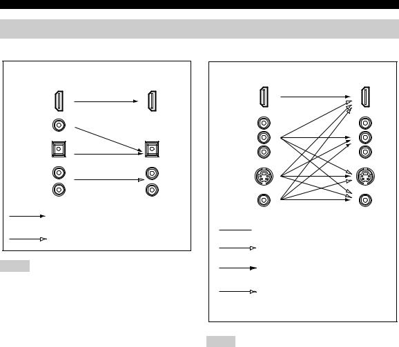
Audio and video signal flow
■ Audio signal flow |
■ Video signal flow |
Input |
Output |
HDMI
DIGITAL AUDIO (COAXIAL)
DIGITAL AUDIO (OPTICAL)
AUDIO
Digital output
Analog output
Notes
•2-channel as well as multi-channel PCM, Dolby Digital and DTS signals input at the HDMI IN 1, HDMI IN 2 or HDMI IN 3 jack can be output at the HDMI OUT jack only when “Support Audio” is set to “Other” (see page 106).
•Audio signals input at the HDMI IN jacks are not output at the analog AUDIO OUT and DIGITAL OUTPUT jacks.
Input |
Output |
HDMI
COMPONENT
VIDEO
S VIDEO
VIDEO
 Through
Video conversion (see page 93)
Component interlace/progressive up-conversion (see page 93)
HDMI interlace/progressive up-conversion and resolution upscaling (see page 93)
Notes
•When the analog video signals are input at the COMPONENT VIDEO, S VIDEO and VIDEO jacks, the priority order of the input signals is as follows:
1.COMPONENT VIDEO
2.S VIDEO
3.VIDEO
•The analog video signals output at the COMPONENT VIDEO jacks can be deinterlaced from 480i (NTSC)/576i (PAL) to 480p/576p. Set “Component I/P” to “On” in “Video” to activate this feature (see page 93).
•Digital video signals input at the HDMI IN 1, HDMI IN 2 or HDMI IN
3jack cannot be output to analog video output jacks.
•The analog component video signals with 480i (NTSC)/576i (PAL) of resolution are converted to the S-video or composite video signals and output at the S VIDEO MONITOR OUT and VIDEO MONITOR OUT jacks.
•Component interlace/progressive conversion (see page 93) and HDMI up-scaling (see page 93) are available only when “Conversion” is set to “On” (see page 93).
•Use the “HDMI Up-Scaling” parameter in “Video” to deinterlace and convert the resolution of the analog video signals output at the HDMI OUT jack (see page 93).
•The GUI screen signal is not output at the VCR 1 OUT and DVR/VCR 2 OUT jacks and is not recorded.
22 En

CONNECTIONS
Connecting a TV monitor or projector
Connect your TV (or projector) to the HDMI OUT jack, the COMPONENT VIDEO MONITOR OUT jacks, the S VIDEO MONITOR OUT jack or the VIDEO MONITOR OUT jack of this unit.
CAUTION
Do not connect this unit or other components to the AC power supply until all connections between components are complete.
y
You can select to play back HDMI audio signals on this unit or on another HDMI component connected to the HDMI OUT jack on the rear panel of this unit. Use the “Support Audio” parameter in “Option” to select the component to play back HDMI audio signals (see page 106).
Notes
•Some video monitors connected to this unit via a DVI connection fail to recognize the HDMI audio/video signals being input if they are in the standby mode. In this case, the HDMI indicator flashes irregularly.
•Set “Conversion” in “Video” to “On” (see page 93) to display the short message displays.
•Set “Wall Paper” in “Video” to “Yes” or “Gray” (see page 95) to display the parameter displays.
•The GUI screen appears with the wall paper or gray background depending on the input video signal format and the setting of the parameters in “Wall Paper” (see page 95).
COMPONENTVIDEO |
MONITOR OUT |
Y |
PB |
HDMI |
PR |
OUT |
MONITOR OUT
SVIDEO
VIDEO |
PREPARATION
Y |
PB |
PR |
V |
S |
|
Component video in |
|
Video in |
HDMI in |
|
S-video in |
|
||
|
|
|
|
TV |
|
|
(or projector) |
|
indicates recommended connections
indicates alternative connections
English
23 En
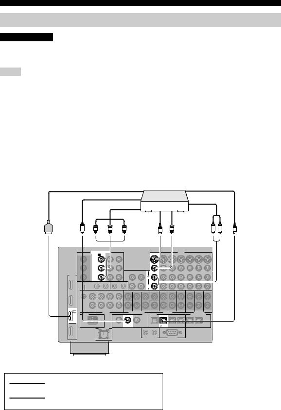
CONNECTIONS
Connecting other components
CAUTION
Do not connect this unit or other components to the AC power supply until all connections between components are complete.
Notes
•When “Conversion” is set to “Off” (see page 93), be sure to make the same type of video connections as those made for your TV (see page 23). For example, if you connected your TV to the VIDEO MONITOR OUT jack of this unit, connect your other components to the VIDEO jacks.
•When “Conversion” is set to “On” (see page 93), the converted video signals are output only at the MONITOR OUT jacks. When recording a source, you must make the same type of video connections between each component.
•To make a digital connection to a component other than the default component assigned to each DIGITAL INPUT or DIGITAL OUTPUT jack, select the corresponding setting for “Option”, “Optical Output”, or “Coaxial Input” in “I/O Assignment” (see page 87).
•If you connect your DVD player to both the DIGITAL INPUT (OPTICAL) and the DIGITAL INPUT (COAXIAL) jacks, priority is given to the signals input at the DIGITAL INPUT (COAXIAL) jack.
•The short message display does not appear when the component video signals with 720p, 1080i or 1080p resolutions are input.
•The short message display does not appear when the component video signals with 480p/576p resolutions are input and output at the VIDEO or S VIDEO MONITOR OUT jack.
■ Connecting a DVD player
|
|
|
|
DVD player |
|
|
|
|
|
|
|
HDMI out |
|
|
Optical out |
|
|
|
|
|
Coaxial out |
|
|
Audio out |
|
|
|
|
|
|
|
|
|
|
|
|
|
Component out |
|
|
|
|
|
|
|
|
|
S-video out |
Video out |
|
|
|
|
C |
PR |
PB |
Y |
S |
V |
R |
L |
O |
|
|
|
||||||
COMPONENTVIDEO
A DVD
Y
PB
HDMI
PR
IN1
DVD
2
DVD
VIDEO
DVD
L
R
DIGITAL INPUT
COAXIAL |
OPTICAL |
5 DVD
indicates recommended connections
indicates alternative connections
24 En

CONNECTIONS
■ Connecting a DVD recorder, PVR or VCR
Note
*1 When you connect another VCR to this unit, connect it to the VCR 1 terminals (S VIDEO IN, VIDEO IN, AUDIO IN, S VIDEO OUT, VIDEO OUT and AUDIO OUT jacks) same as DVR/VCR 2 terminals except the DIGITAL INPUT (COAXIAL) jack.
VIDEO |
|
|
*1 |
IN VCR 1 |
OUT IN |
DVR/VCR 2 OUT |
|
L |
|
|
|
R |
|
|
|
|
IN |
DVR/VCR 2 |
OUT |
DIGITAL INPUT |
DIGITAL OUTPUT |
|
|
COAXIAL |
|
OPTICAL |
|
3 VCR2DVR/ |
9 CD-R |
|
|
PREPARATION
out Coaxial
C
out video-S
S
 out Video
V
out Audio
L |
R |
in Audio
R |
L |
in Video
V
in video-S
S
DVD recorder, PVR or VCR
■ Connecting set-top boxes
out HDMI |
out Component |
O |
Optical |
PR PB |
Y |
out |
|
|
|
|
HDTV decoder
R L |
outAudio |
outVideo |
V |
S |
outvideo-S |
|
|
|
|||
|
|
|
|
||
|
|
|
|
|
S |
video-S |
|
out |
||
|
Satellite receiver, |
|
|
|
|
|||
cable TV receiver |
|
|
HDMI out |
|
|||
|
|
|
|
|
|
|
|
|
|
|
|
|
Component out |
|
|
|
|
|
|
|
Optical out |
|
|
|
Video |
L |
R |
Audio |
|
|
|
V |
out |
out |
O |
PR PB |
Y |
||
|
|
|
|
||||
COMPONENTVIDEO |
VIDEO |
DTV CBL/SAT |
DTV CBL/SAT |
Y |
|
PB |
|
HDMI |
|
PR |
L |
IN3 |
|
R
CBL/
SAT
IN2
DTV
DIGITAL INPUT
|
OPTICAL |
6 DTV |
7 CBL/SAT |
English
25 En
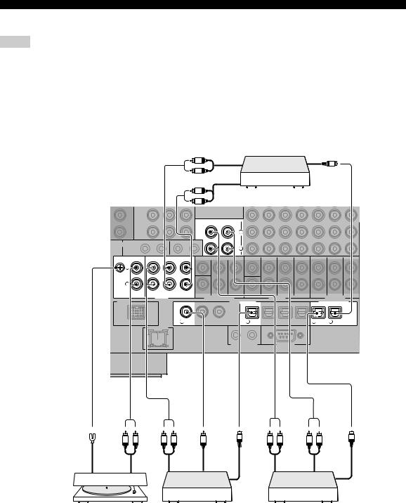
CONNECTIONS
■ Connecting audio components
Notes
•To make a digital connection to a component other than the default component assigned to either the DIGITAL INPUT jack or the DIGITAL OUTPUT jack, select the corresponding setting for “Option”, “Optical Output”, or “Coaxial Input” in “I/O Assignment” (see page 87).
•Connect your turntable to the GND terminal of this unit to reduce noise in the signal. However, you may hear less noise without the connection to the GND terminal for some turntables.
•The PHONO jacks are only compatible with a turntable with an MM or a high-output MC cartridge. To connect a turntable with a lowoutput MC cartridge to the PHONO jacks, use an in-line boosting transformer or an MC-head amplifier.
•When you connect both the DIGITAL INPUT (OPTICAL) jack and the DIGITAL INPUT (COAXIAL) jack to an audio component, the priority is given to the DIGITAL INPUT (COAXIAL) jack.
Audio out |
Optical in |
L |
O |
|
 R
R
L
R
Audio in
CD recorder
IN |
OUT |
|
(PLAY) |
(REC) |
|
MD/ |
L |
|
TAPE |
||
|
R
GND |
PHONO |
CD |
CD-R |
L
R
IN(PLAY) OUT(REC)
AUDIO
|
|
DIGITAL INPUT |
|
DIGITAL OUTPUT |
||
|
|
COAXIAL |
|
|
|
OPTICAL |
1 |
CD |
4 |
CD |
8 |
TAPEMD/ |
9 CD-R |
O O
R L R L C R L R L
Ground |
Audio out |
Audio |
Coaxial |
Optical |
Audio |
Audio |
|
|
out |
out |
out |
out |
in |
Optical in
Turntable |
CD player |
MD recorder or |
|
|
tape deck |
26 En
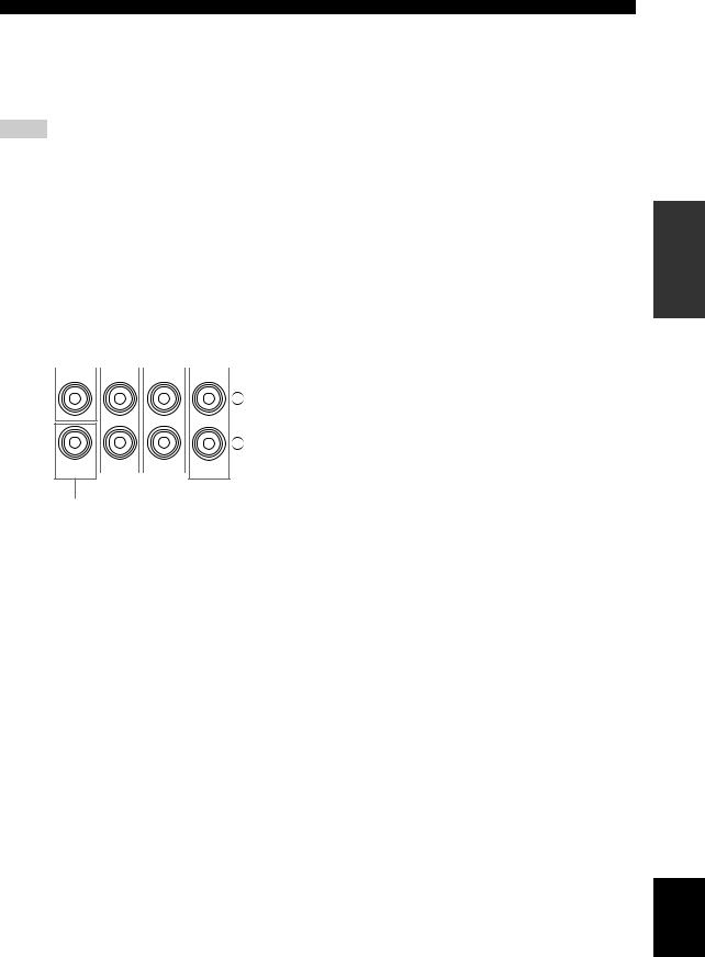
■ Connecting an external amplifier
This unit has more than enough power for any home use. However, if you want to add more power to the speaker output or if you want to use another amplifier, connect an external amplifier to the PRE OUT jacks.
Notes
•When you make connections to the PRE OUT jacks, do not make connections to the SPEAKERS terminals.
•The signals output at the FRONT PRE OUT and CENTER PRE OUT jacks are affected by the TONE CONTROL settings (see page 52).
•Each PRE OUT jack outputs the same channel signals as the corresponding SPEAKERS terminals.
•Adjust the volume level of the subwoofer with the control on the subwoofer (see page 53).
•Some signals may not be output at the SUBWOOFER PRE OUT jack depending on the settings for “Speaker Set” (see page 96) and “Bass Out” (see page 98).
1 |
|
2 |
3 |
|
4 |
|||||
|
|
|
|
|
|
|
|
|
|
|
CENTER |
|
FRONT |
|
SURROUND SINGLE(SB) |
||||||
L
R
SUB |
|
|
|
SUR.BACK/ |
WOOFER |
|
|
|
PRESENCE |
|
|
PRE OUT
5
1CENTER PRE OUT jack
Center channel output jack.
2FRONT PRE OUT jacks
Front channel output jacks.
3SURROUND PRE OUT jacks
Surround channel output jacks.
4SURROUND BACK/PRESENCE PRE OUT jacks
Surround back or presence channel output jacks. When you only connect one external amplifier for the surround back channel, connect it to the SINGLE (SB) jack.
y
•Set the “Surround Back” to “Large x2”, “Large x1”, “Small x2” or “Small x1” and “Presence” to “None” (see page 97) to output the surround back channel signals at SURROUND BACK/ PRESENCE PRE OUT jacks.
•Set the “Presence” to “Yes” and “Surround Back” to “None” (see page 97) to output the presence channel signals at SURROUND BACK/PRESENCE PRE OUT jacks.
5 SUBWOOFER PRE OUT jack
Connect a subwoofer with a built-in amplifier.
CONNECTIONS
PREPARATION
English
27 En
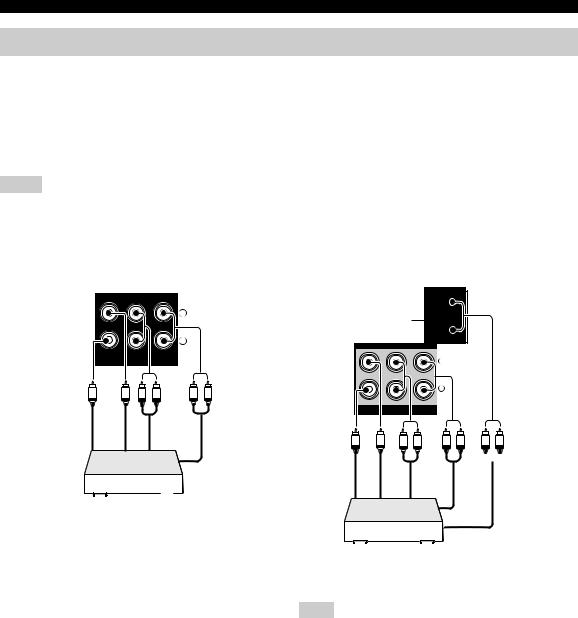
CONNECTIONS
Connecting a multi-format player or an external decoder
This unit is equipped with 6 additional input jacks (left and right FRONT, CENTER, left and right SURROUND and SUBWOOFER) for discrete multi-channel input from a multi-format player, external decoder, sound processor or pre-amplifier.
If you set “Input Channels” to “8ch” in “MULTI CH” (see page 88), you can use the input jacks assigned as “Front Input” in “Multi CH Assign” (see page 88) together with the MULTI CH INPUT jacks to input 8-channel signals. Connect the output jacks on your multi-format player or external decoder to the MULTI CH INPUT jacks. Be sure to match the left and right outputs to the left and right input jacks for the front and surround channels.
Notes
•When you select the component connected to the MULTI CH INPUT jacks as the input source (see page 43), this unit automatically turns off the digital sound field processor, and you cannot select sound field programs.
•This unit does not redirect signals input at the MULTI CH INPUT jacks to accommodate for missing speakers. We recommend that you connect at least a 5.1-channel speaker system before using this feature.
For 6-channel input |
For 8-channel input |
CENTER |
FRONT(6CH) SURROUND |
|
L |
|
R |
SUB |
SB(8CH) |
WOOFER |
MULTI CH INPUT
|
L |
R |
L |
R |
Subwoofer out |
out Center |
|
out Front |
Surround out |
Multi-format player/
External decoder
(PLAY) |
(REC) |
|
|
MD/ |
|
L |
|
TAPE |
|
|
|
*1 |
|
||
UT |
|
||
|
|
R |
|
CENTER |
FRONT(6CH) SURROUND |
CENTER |
|
|
|
|
L |
|
|
|
R |
SUB |
SB(8CH) |
SUB |
|
WOOFER |
WOOFER |
||
MULTI CH INPUT |
|
||
Subwoofer out |
outCenter |
outbackSurround |
L R |
|
L |
R |
|
out Surround
L R
out Front
Multi-format player/
External decoder
Note
*1 The analog audio input jacks assigned as “Front Input” in “Multi CH Assign” (see page 88).
28 En
Loading...