


 Loading...
F
English
Русский
AV Receiver/АВ ресивер
Easy Setup Guide Руководство по быстрой настройке
AV Receiver
Easy Setup Guide
English
This document explains how to set up a 5.1- or 7.1-channel system (RX-V575 only) and play back surround sound from a BD/DVD on the unit.
To reduce the impact on natural resources, the Owner’s Manual for this product is
supplied on CD-ROM. For more information about this product, refer to the
Owner’s Manual on the supplied CD-ROM.
PDF versions of this guide and “Owner’s Manual” can be downloaded from the following website.
http://download.yamaha.com/
[For U.S. customers only]
Visit the following website for additional information, FAQ’s, downloads such as “Owner’s Manual” and product updates.
http://usa.yamaha.com/support/
1 Preparation
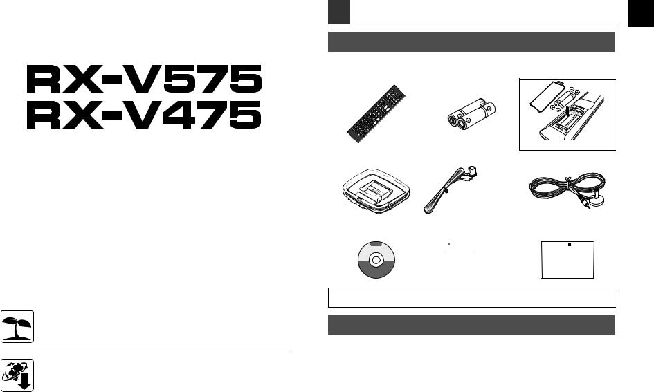
Accessories
Check that the following accessories are supplied with the product.
Remote control |
Batteries |
|
(AAA, R03, UM-4) (x2) |
|
|
Insert the batteries the right way round. |
AM antenna |
FM antenna |
YPAO microphone |
*The supplied FM antenna varies depending on the region of purchase.
CD-ROM |
Safety Brochure |
Easy Setup Guide |
||||||||||||||||||
(Owner’s Manual) |
|
|
|
|
|
|
|
|
|
|
|
|
|
|
||||||
|
|
|
|
|
|
|
|
|
|
|
|
|
|
|
|
|
|
|
|
|
|
|
|
|
|
|
|
|
|
|
|
|
|
|
|
|
|
|
|
|
|
|
|
|
|
|
|
|
|
|
|
|
|
|
|
|
|
|
|
|
|
|
|
|
|
|
|
|
|
|
|
|
|
|
|
|
|
|
|
|
|
|
|
|
|
|
|
|
|
|
|
|
|
|
|
|
|
|
|
|
|
|
|
|
|
|
|
|
|
|
|
|
|
|
|
|
|
|
|
|
|
|
|
|
|
|
|
|
|
|
|
|
|
|
|
|
|
|
|
|
|
|
|
|
|
|
|
|
|
|
|
|
|
|
|
|
|
|
|
|
|
|
|
|
|
|
|
|
|
|
|
|
|
|
|
|
|
|
|
|
|
|
|
|
|
|
|
|
•The illustrations of the main unit and remote control used in this guide are of the RX-V575 (U.S.A. model), unless otherwise specified.
Cables required for connections
The following cables (not supplied) are required to build the system described in this document.
•Speaker cables (depending on the number of speakers)
•HDMI cable (x2)
•Audio pin cable (x1)
•Digital optical cable (x1) (not required if your TV supports ARC [Audio Return Channel])
En 1
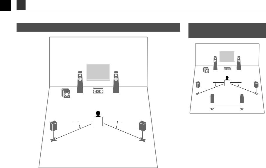
2 Placing speakers
Set up the speakers in the room using the following diagram as a reference.
For information on other speaker systems, refer to “Owner’s Manual”.
5.1-channel system
1 2
9  3
3 
4 
 5
5
10° to 30° |
|
|
|
|
|
10° to 30° |
|
|
|
|
|||
|
|
|
|
|
7.1-channel system (RX-V575 only)
1 2
9  3
3 
4 5
10° to 30° |
|
|
|
|
|
10° to 30° |
6 |
|
|
7 |
|||
30 cm (1 ft) or more
1Front speaker (L)
2Front speaker (R)
3Center speaker
4Surround speaker (L)
5Surround speaker (R)
6Surround back speaker (L)
7Surround back speaker (R)
9Subwoofer
2En

3 Connecting speakers/subwoofer
•(U.S.A. and Canada models only)
Under its default settings, the unit is configured for 8-ohm
speakers. When connecting 6-ohm speakers, set the unit’s speaker impedance to “6 Ω MIN”. For details, see “Setting the speaker impedance” in “Owner’s Manual”.
•(Except for U.S.A. and Canada models)
Use speakers with an impedance of at least 6 Ω.
•Use a subwoofer equipped with built-in amplifier.
•Before connecting the speakers, remove the unit’s power cable from the AC wall outlet and turn off the subwoofer.
•Ensure that the core wires of the speaker cable do not touch each other or come into contact with the unit’s metal areas. This may damage the unit or the speakers. If the speaker cables short circuit, “Check SP Wires” will appear on the front display when the unit is turned on.
1 Connect the front speakers (1/2) |
2 Connect the center speaker (3) to the |
||
to the FRONT (//\) terminals. |
CENTER terminal. |
|
|
The unit (rear) |
The unit (rear) |
||
|
SPEAKERS |
|
SPEAKERS |
FRONT |
CENTER SURROUND |
FRONT |
CENTER SURROUND |
1 |
|
1 |
|
2 |
|
2 |
|
UBWOOFER |
|
SUBWOOFER |
|
PRE OUT |
|
PRE OUT |
|
■ Connecting speaker cables
Speaker cables have two wires. One is for connecting the negative (–) terminals of the unit and the speaker, and the other is for the positive (+) terminals. If the wires are colored to prevent confusion, connect the black wire to the negative and the other wire to the positive terminals.
a Remove approximately 10 |
c |
|
mm (3/8”) of insulation |
||
+ (red) b |
||
from the ends of the |
|
|
speaker cable and twist |
d a |
|
the bare wires of the cable |
||
firmly together. |
– (black) |
b Loosen the speaker terminal.
c Insert the bare wires of the cable into the gap on the side (upper right or bottom left) of the terminal.
d Tighten the terminal.
Using a banana plug |
a |
(U.S.A., Canada, China, |
|
Australia and General |
Banana plug |
|
|
models only) |
|
a Tighten the speaker |
b |
terminal. |
|
b Insert a banana plug into the end of the terminal.
1 |
2 |
|
1 |
2 |
9 |
3 |
|
9 |
3 |
4 |
|
5 |
4 |
5 |
En 3
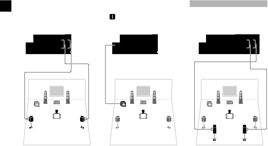
3 Connect the surround speakers (4/ |
4 Connect the subwoofer (9) to the |
5) to the SURROUND (//\) |
SUBWOOFER PRE OUT jack. |
terminals. |
|
|
• Use a subwoofer equipped with built-in amplifier. |
The unit (rear) |
The unit (rear) |
SPEAKERS |
SPEAKERS |
FRONT CENTER SURROUND |
FRONT CENTER SURROUND |
For 7.1-channel system (RX-V575 only)
Connect the surround back speakers (6/ 7) to the SURROUND BACK (//\) terminals.
The unit (rear)
|
|
SPEAKERS |
|
|
SURROUND BACK BI AMP |
FRONT |
CENTER |
/ZONE B |
SURROUND |
||
|
|
SINGLE |
1 |
1 |
1 |
2 |
2 |
2 |
SUBWOOFER |
UBWOOFER |
SUBWOOFER |
PRE OUT |
PRE OUT |
PRE OUT |
Audio pin cable
1 |
2 |
1 |
2 |
1 |
2 |
9 |
3 |
9 |
3 |
9 |
3 |
4 |
5 |
4 |
5 |
4 |
5 |
|
|
|
|
6 |
7 |
4En

4 Connecting external devices
Audio out |
TV |
|
|
|
|
(optical) |
HDMI in |
HDMI out |
|
|
BD/DVD player |
OPTICAL |
HDMI |
HDMI |
O |
HDMI |
HDMI |
|
|
c |
b |
|
|
a |
|
|
|
||
|
|
|
|
|
|
|
|
|
VOLTAGE |
|
|
|
|
SELECTOR |
|
HDMI OUT |
|
|
HDMI 1 jack |
|
jack |
|
|
|
|
HDMI |
HDMI |
110V- |
|
|
|
|
|
120V |
|
HD OUT |
H |
I 1 |
220V- |
|
(B |
VD) |
240V |
|
ARC
|
HDMI OUT |
HDMI 1 |
HDMI 2 |
HDMI 3 |
HDMI 4 |
HDMI 5 |
NETWORK |
|
|
|||
|
(BD DVD) |
|
|
|
|
MHL 5V 1A |
|
NET) |
|
|
||
|
|
|
|
|
|
ANTENNA |
|
|
DC OUT |
|
|
|
|
|
|
|
|
|
(RAD O) FM |
COMPONENT |
V |
0 A |
|
|
|
|
|
|
|
|
|
|
VID O |
|
|
|
|
|
|
PR |
|
|
|
|
|
|
PR |
|
|
|
|
|
|
|
|
|
|
|
|
|
|
|
|
SPEAKERS |
|
|
|
|
|
|
|
|
PB |
|
|
|
SURROUND BACK/BI AMP |
|
|
|
|
|
|
|
|
FRONT |
CENTER |
ZONE B |
||
|
O |
|
|
|
|
|
|
|
SURROUND |
|||
|
|
|
|
|
|
|
|
|
|
|
S NGLE |
|
AV 4 (OPTICAL) jack |
Y |
|
|
OPTICAL |
|
|
|
1 |
|
|
|
|
COMPONENT |
|
|
AV 4 |
|
|
|
|
|
|
|
||
|
|
|
(TV) |
|
|
MONITOR OUT |
|
|
|
|
||
|
VI EO |
|
|
|
|
|
|
|
|
|
|
|
|
OPT C L |
OAX AL |
C AX AL |
O T CAL |
|
|
|
2 |
|
|
|
|
|
|
AV |
|
UBWOO ER |
|
|
|
|
||||
|
AV 1 |
AV 2 |
AV 3 |
( V ) |
AV 5 |
OUT |
UD O |
PRE OU |
|
|
|
|
|
AV 4 |
AV 6 |
|
|
|
|
|
|||||
|
|
|
|
|
|
|
|
|
The unit (rear) |
|
||
Turn on the unit |
|
YPAO M C |
|
|
|
|
|
|
|
|
|
|
|
|
|
|
|
|
INFO |
MEMORY |
PR SET |
FM |
AM |
TUNING |
|
|
|
|
|
|
|
|
|
|
SCENE |
|
|
|
|
|
|
|
|
|
|
|
BD |
TV |
NET |
RADIO |
|
|
|
|
|
|
|
|
|
DVD |
|
|||
VOLTAGE SELECTOR (General model only)
d
To an AC wall outlet
D RECT
VOLUME
|
INPUT |
TONE CONTROL |
|
VIDEO AUX |
|
|
PHONES |
PROGRAM |
STRA GHT |
|
|
||
SILENT C NEMA |
|
|
|
AUD O |
V DEO |
5V 2 1A |
|
|
|
|
|||
The unit (front)
Before connecting the power cable (General model only)
Make sure you set the switch position of
VOLTAGE SELECTOR according to your local voltage. Voltages are AC 110-120/220-240 V, 50/60 Hz.
1 Connect external devices to the unit.
a Connect a BD/DVD player to the unit with an HDMI cable.
If the BD/DVD player is currently connected to the TV directly with an HDMI cable, disconnect the cable from the TV and connect it to this unit.
b Connect a TV to the unit with the other HDMI cable.
c Connect a TV to the unit with a digital optical cable.
This connection is required to play back TV audio on the unit. This connection is not required if your TV supports ARC (Audio Return Channel).
d Connect the power cable to an AC wall outlet.
•For information on how to connect radio antennas or other external devices, see “PREPARATIONS” in “Owner’s Manual”.
2Turn on the unit, the TV and the BD/DVD player.
3Use the TV remote control to change the TV input to video from the unit.
The connections are complete. Proceed to the next page to optimize the speaker settings.
•By connecting a TV to the unit with an HDMI cable, you can configure the unit’s settings with the menu displayed on the TV. In addition, you can select the on-screen menu language from English (default), Japanese, French, German, Spanish, Russian, Italian and Chinese. For details, refer to “Owner’s Manual”. In this guide, illustrations of English menu screens are used as examples.
En 5
Loading...