


Yamaha YP400T, YP400V, YP400W, 2005 YP400T, 2005 YP400V Service Manual
...2005 - 2007
|
|
|
|
|
net |
|
|
|
|
. |
|
|
|
|
ScooterTime |
|
|
MOTORCYCLE |
|
|
|||
|
|
. |
|
|
|
|
|
www |
|
|
|
SERVICE MANUAL |
|
|
|||
Downloaded |
from |
|
|
|
|
|
|
|
|
|
|
Model : YP400T, YP400V, YP400W
5RU281972000 *5RU281972000*

|
|
|
|
net |
|
|
|
. |
|
|
|
|
ScooterTime |
|
|
|
. |
|
|
|
from |
www |
|
|
|
|
|
|
|
DownloadedEAS00000 |
|
|
|
|
|
|
YP400T |
|
|
|
SERVICE MANUAL |
|
||
|
©2004 by Yamaha Motor Co., Ltd. |
|
||
|
First edition, June 2004 |
|
||
|
All rights reserved. |
|
||
|
Any reproduction or unauthorized use |
|
||
|
without the written permission of |
|
||
|
Yamaha Motor Co., Ltd. |
|
||
|
is expressly prohibited. |
|
||
|
|
|
|
|
EAS00002
NOTICE
This manual was produced by the Yamaha Motor Company, Ltd. primarily for use by Yamaha dealers and their qualified mechanics. It is not possible to include all the knowledge of a mechanic in one manual. Therefore, anyone who uses this book to perform maintenance and repairs on Yamaha vehicles should have a basic understanding of mechanics and the techniques to repair these types of vehicles. Repair and maintenance work attempted by anyone without this knowledge is likely to render the vehicle unsafe and unfit for use.
Yamaha Motor Company, Ltd. is continually striving to improve all of its models. Modifications and significant changes in specifications or procedures will be forwarded to all authorized Yamaha dealers and will appear in future editions of this manual where applicable.
NOTE:
Designs and specifications are subject to change without notice.
EAS00005 |
|
from |
||
IMPORTANT MANUAL INFORMATION |
||||
Particularly important information is distinguished in this manual by the following. |
||||
|
|
|
Downloaded |
|
|
|
|
The Safety Al rt Symbol means ATTENTION! BECOME ALERT! YOUR |
|
|
|
|
SAFETY IS INVOLVED! |
|
|
WARNING |
Failure to follow WARNING instructions could result in severe injury or death to |
||
|
|
|
the scooter operator, a bystander or a person checking or repairing the scooter. |
|
|
|
|
||
|
CAUTION: |
|
A CAUTION indicates special precautions that must be taken to avoid damage |
|
|
|
|
to the scooter. |
|
NOTE: |
A NOTE provides key information to make procedures easier or clearer. |
|||

EAS00007
HOW TO USE THIS MANUAL
This manual is intended as a handy, easy-to-read reference book for the mechanic. Comprehensive explanations of all installation, removal, disassembly, assembly, repair and check procedures are laid out with the individual steps in sequential order.
1 The manual is divided into chapters. An abbreviation and symbol in the upper right corner of each page indicate the current chapter.
Refer to “SYMBOLS”.
2 Each chapter is divided into sections. The current section title is shown at the top of each page, except in Chapter 3 (“PERIODIC CHECKS AND ADJUSTMENTS”), where the sub-section title(s) appears.
3 Sub-section titles appear in smaller print than the section title.
4 To help identify parts and clarify procedure steps, there are exploded diagrams at the start of each removal and disassembly section.
5 Numbers are given in the order of the jobs in the exploded diagram. A circled number indicates a
disassembly step. |
. |
|
|
||
ScooterTime |
net |
|
6 Symbols indicate parts to be lubricated or replaced. |
|
|
Refer to “SYMBOLS”.
7 A job instruction chart accompanies the exploded diagram, p oviding the order of jobs, names of parts, notes in jobs, etc.
8 Jobs requiring more information (such as special tools and technical data) are described sequen-
tially. |
|
|
|
|
. |
|
from |
www |
Downloaded |
|
|
|
|

1 |
2 |
GEN |
SPEC |
|
INFO |
||
|
||
3 |
4 |
|
CHK |
CHAS |
|
ADJ |
||
|
||
5 |
6 |
|
ENG |
COOL |
|
7 |
8 |
|
FI |
ELEC – + |
|
9 |
0 |
TRBL
SHTG
A B
C |
|
D |
from |
|
|
Downloaded |
|
|
|
T |
|
|
|
. |
|
|
|
R |
|
|
|
. |
|
E |
F |
G |
|
EAS00008
SYMBOLS
The following symbols are not relevant to every vehicle.
Symbols 1 to 9 indicate the subject of each chapter.
1 General information
2Specifications
3Periodic checks and adjustments
4Chassis
5Engine
6Cooling system
7Fuel injection system
8Electrical system
9Troubleshooting
|
net |
. |
|
ScooterTime |
|
Symbols 0 to G indicate the following. |
|
0 Servic able with engine mounted |
|
A Filling fluid |
|
B Lubricant |
|
C Spe ial tool |
|
. |
|
D Tightening torque |
|
www |
|
E Wear limit, clearance |
|
F Engine speed |
|
G Electrical data |
|
H I J
E G M
K L M
B |
LS |
M |
N O
New
LT
Symbols H to M in the exploded diagrams indicate the types of lubricants and lubrication points.
H Engine oil I Gear oil
JMolybdenum-disulfide oil
KWheel-bearing grease
LLithium-soap-based grease
MMolybdenum-disulfide grease
Symbols N to O in the exploded diagrams indicate the following.
N Apply locking agent (LOCTITE®) O Replace the part

GEN
INFO
CHAPTER 1
GENERAL INFORMATION
SCOOTER IDENTIFICATION.......................................................................... |
|
|
|
|
1-1 |
|
VEHICLE IDENTIFICATION NUMBER ..................................................... |
|
|
|
1-1 |
||
MODEL LABEL.......................................................................................... |
|
|
|
|
|
1-1 |
FEATURES...................................................................................................... |
|
|
|
|
|
1-2 |
OUTLINE OF THE FI SYSTEM................................................................. |
|
|
|
|
1-2 |
|
FI SYSTEM................................................................................................ |
|
|
|
|
|
1-3 |
INSTRUMENT FUNCTIONS ..................................................................... |
|
|
|
|
1-4 |
|
IMPORTANT INFORMATION ....................................................................... |
|
|
|
|
1-10 |
|
PREPARATION FOR REMOVAL AND DISASSEMBLY |
......................... |
|
1-10 |
|||
REPLACEMENT PARTS................................................... |
|
|
|
|
...............1-10 |
|
GASKETS, OIL SEALS AND O-RINGS |
|
. net |
1-10 |
|||
|
|
|
||||
LOCK WASHERS/PLATES AND COTTER PINS ................................... |
|
|
1-11 |
|||
BEARINGS AND OIL SEALS .................................................................. |
|
|
|
|
1-11 |
|
CIRCLIPS ................................................................................................ |
|
|
|
|
|
1-11 |
CHECKING THE CONNECTIONS ............ |
|
..............................................1-12 |
||||
|
|
. |
|
|
|
|
|
|
www |
ScooterTime |
|
|
|
SPECIAL TOOLS .......................................................................................... |
|
|
|
|
1-13 |
|
|
from |
|
|
|
|
|
Downloaded |
|
|
|
|
|
|
|
|
|
|
|
|
|

GEN
SCOOTER IDENTIFICATION INFO
 1
1
1
Downloaded |
from |
|
EAS00015
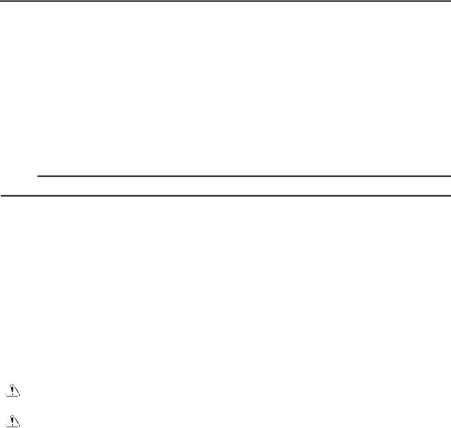
GENERAL INFORMATION
SCOOTER IDENTIFICATION
EAS00017
VEHICLE IDENTIFICATION NUMBER
The vehicle identification number 1 is stamped into the frame.
EAS00018 |
|
|
MODEL LABEL |
|
|
The model label 1 is affixed inside the storage |
||
box. Record the information on this label in the |
||
space provided. This information will be |
||
|
|
net |
needed when ordering spare parts. |
||
|
. |
|
|
ScooterTime |
|
|
|
|
. |
|
|
www |
|
|
1 - 1
FEATURES
EAS00896
FEATURES
OUTLINE OF THE FI SYSTEM
GEN INFO
The main function of a fuel supply system is to provide fuel to the combustion chamber at the optimum air-fuel ratio in accordance with the engine operating conditions and the atmospheric temperature. In the conventional carburetor system, the air-fuel ratio of the mixture that is supplied to the combustion chamber is created by the volume of the intake air and the fuel that is metered by the jet used in the respective carburetor.
Despite the same volume of intake air, the fuel volume requirement varies by the engine operating conditions, such as acceleration, deceleration, or operating under a heavy load. Carburetors that meter the fuel through the use of jets have been provided with various auxiliary devices, so that an optimum air-fuel ratio can be achieved to accommodate the constant changes in the operating conditions of the engine.
As the requirements for the engine to deliver more performance and cleaner exhaust gases increase, it becomes necessary to control the air-fuel ratio in a more precise and finely tuned manner. To accommodate this need, this model has adopted an electronicallynetcontrolled fuel injection (FI) system, in place of the conventional carburetor system. This syst .m can achieve an optimum air-fuel ratio required by the engine at all times by using a microprocessor that regulates the fuel injection volume according to the engine operating conditions detected by various sensors.
The adoption of the FI system has resulted in a highly pr cise fuel supply, improved engine
response, better fuel economy, and reduced exhaust emissi |
ns. |
|
|||||
|
|
3 |
|
|
ScooterTime |
|
|
|
|
|
|
|
|
||
|
|
|
|
. |
|
|
|
|
|
|
|
7 9 |
A |
B |
|
|
2 |
|
|
www |
8 |
0 |
|
|
|
|
|
|
|
||
|
|
|
|
|
|
|
|
|
|
|
|
6 |
|
|
|
1 |
|
|
4 |
|
|
|
|
|
Downloaded |
from |
|
|
|
|
|
|
|
5 |
|
|
|
|
|
|
|
|
|
|
|
|
|
|
H |
F |
|
D |
C |
|
I |
G |
E |
|
|
|
|
|
|||
|
|
|
|
||
1 ECU |
5 Fuel hose |
0 ISC (idle speed con- |
E Crankshaft position |
||
2 Fuel injection system |
6 Ignition coil |
trol) valve |
|
|
sensor |
relay |
7 Fuel injector |
A Intake air temperature |
F Coolant temperature |
||
3 Engine trouble warn- |
8 Intake air pressure |
sensor |
|
|
sensor |
ing light |
sensor |
B Battery |
|
|
G Spark plug |
4 Lean angle cut-off |
9 Throttle position sen- |
C Air filter case |
|
H Fuel tank |
|
switch |
sor |
D Catalytic converter |
|
I Fuel pump |
|
1 - 2

FEATURES
EAS00897
FI SYSTEM
GEN INFO
The fuel pump delivers fuel to the fuel injector via the fuel filter. The pressure regulator maintains the fuel pressure that is applied to the fuel injector at only 250 kPa (2.5 kg/cm2, 35.6 psi). Accordingly, when the energizing signal from the ECU energizes the fuel injector, the fuel passage opens, causing the fuel to be injected into the intake manifold only during the time the passage remains open. Therefore, the longer the length of time the fuel injector is energized (injection duration), the greater the volume of fuel that is supplied. Conversely, the shorter the length of time the fuel injector is energized (injection duration), the lesser the volume of fuel that is supplied.
The injection duration and the injection timing are controlled by the ECU. Signals that are input from the throttle position sensor, crankshaft position sensor, intake air pressure sensor, intake temperature sensor and coolant temperature sensor enable the ECU to determine the injection duration. The injection timing is determined through the signals from the crankshaft position sensor. As a
|
|
|
|
|
|
net |
imes in accordance |
|
result, the volume of fuel that is required by the engine can be supplied at all |
||||||||
with the driving conditions. |
|
|
|
|
. |
|
|
|
|
|
|
|
|
|
|
|
|
|
|
|
|
|
ScooterTime |
C |
|
|
|
|
|
|
|
|
|
|
|
|
|
|
|
Ê |
|
B |
|
|
|
|
|
|
4 |
|
|
||
|
|
|
|
|
|
|
|
|
|
|
|
2 |
. |
|
|
|
|
|
|
È |
|
|
|
|
||
|
|
|
www |
|
|
|
|
|
|
1 |
|
from |
|
3 |
|
|
|
|
|
|
|
|
|
|||
A |
|
|
|
|
|
|
5 |
|
|
|
|
|
|
|
|
||
|
É |
|
|
|
|
|
|
|
|
Downloaded |
|
|
|
|
|
|
|
|
0 |
9 |
|
|
|
|
|
|
|
|
8 |
|
|
|
6 |
|
|
|
|
|
|
|
|
|
|
|
|
|
|
|
|
|
7 |
|
|
Illustration is for reference only.
1 Fuel pump |
7 Crankshaft position |
A Air filter case |
È Fuel system |
2 Fuel injector |
sensor |
B Throttle position sen- |
É Air system |
3 Ignition coil |
8 Intake air pressure |
sor |
Ê Control system |
4 ECU |
sensor |
C ISC (idle speed con- |
|
5 Catalytic converter |
9 Throttle body |
trol) valve |
|
6 Coolant temperature |
0 Intake air temperature |
|
|
sensor |
sensor |
|
|
1 - 3

GEN
FEATURES INFO
1 |
2 |
3 |
4 |
5 |
6 |
1 |
2 |
3 |
4 |
Downloaded |
from |
|
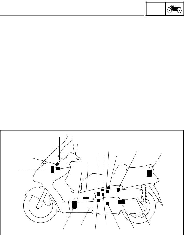
INSTRUMENT FUNCTIONS
Multifunction display
 WARNING
Be sure to stop the vehicle before making any setting changes to the multifunction display.
1 Clock/ambient temperature display
2 Coolant temperature meter
3 Fuel meter
4Odometer/tripmeters
5“SELECT” button
6“RESET” button
1 V-belt replacement indicator “V-BELT” |
|||||||||
2 Fuel level warning symbol “ |
|
|
” |
|
|||||
|
|
|
|||||||
|
|
|
|||||||
|
|
|
net |
|
|
|
|
|
|
3 Coolant temperature symbol “ |
|
|
” |
||||||
|
|
. |
|
|
|
|
|
|
|
4 Oil change indicator “OIL” |
|
||||||||
|
ScooterTime |
|
|
|
|
|
|
|
|
The multifunction display is equipped with the |
|||||||||
following: |
|
|
|
|
|
|
|
||
|
• a fuel meter |
|
|
|
|
|
|
|
|
|
• a coolant temperature meter |
|
|||||||
|
• an |
d meter (which shows |
the total dis- |
||||||
|
tan |
e traveled) |
|
|
|
|
|
|
|
. |
|
|
|
|
|
|
|
|
|
www |
• two tripmeters (which show the distance |
||||||||
traveled since they were last set to zero)
• a fuel reserve tripmeter (which shows the distance traveled since the bottom segment of the fuel meter and fuel level warning symbol started flashing)
• a self-diagnosis device
• a clock
• an ambient temperature display
• an oil change indicator
• a V-belt replacement indicator
NOTE:
•Be sure to turn the key to “ON” before using the “SELECT” and “RESET” buttons.
•When the key is turned to “ON”, all of the display segments of the multifunction display will appear one after the other and then dis-
appear, in order to test the electrical circuit.
CAUTION:
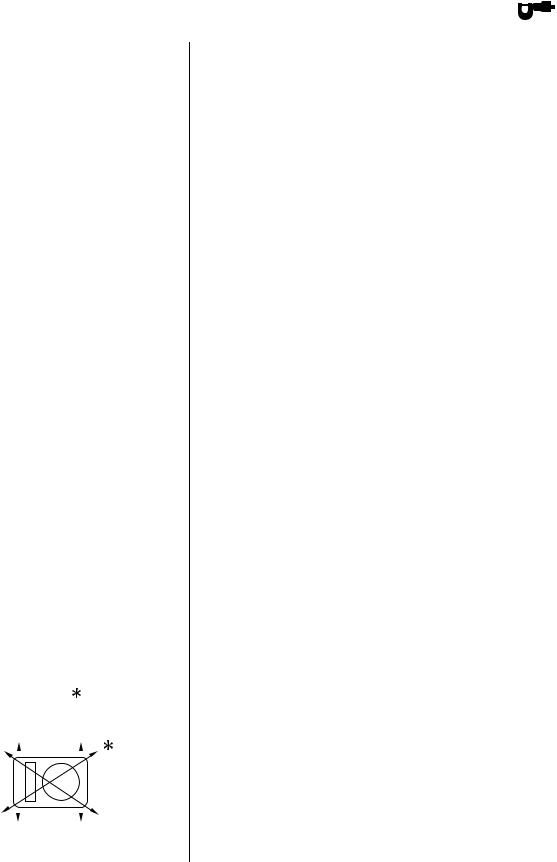
If bars 1 appear where the odometer and tripmeters are normally displayed, the multi-function display is malfunctioning.
Replace the entire multi-function display.

 1
1
1 - 4


 1
1
|
|
|
|
|
|
|
|
|
|
|
|
|
|
|
|
|
|
|
|
|
|
|
|
FEATURES |
|
|
GEN |
|
|
||||
|
|
|
|
|
|
|
|
|
INFO |
|
|
|||||
|
|
|
|
|
|
|
|
|
|
|
|
|
|
|
|
|
|
|
|
|
|
|
|
Odometer and tripmeter modes |
|||||||||
|
|
|
|
|
|
|
Pushing the “SELECT” button switches the |
|||||||||
|
|
|
|
|
|
|
display between the odometer mode “ODO” |
|||||||||
|
|
|
|
|
|
|
and the tripmeter modes “TRIP” in the follow- |
|||||||||
|
|
|
|
|
|
|
ing order: |
|
|
|
|
|
|
|||
|
|
|
|
|
|
|
ODO → TRIP (top) → TRIP (bottom) → ODO |
|||||||||
|
|
|
|
|
|
When approximately 2.8 L (0.62 Imp gal, |
||||||||||
|
|
|
|
|
|
0.74 US gal) of fuel remains in the fuel tank, the |
||||||||||
|
|
|
|
|
|
bottom segment of the fuel meter and fuel level |
||||||||||
|
|
|
|
|
|
warning symbol will start flashing, and the dis- |
||||||||||
|
|
|
|
|
|
play will automatically change to the fuel reserve |
||||||||||
|
|
|
|
|
|
tripmeter mode “TRIP F” and start counting the |
||||||||||
|
|
|
|
|
|
distance traveled from that point. In that case, |
||||||||||
|
|
|
|
|
|
pushing the “SELECT” button switches the dis- |
||||||||||
|
|
|
|
|
|
|
|
|
|
|
net |
|||||
|
|
|
|
|
|
play between the various |
|
ripmeter and odome- |
||||||||
|
|
|
|
|
|
ter modes in the followi g order: |
||||||||||
|
|
|
|
|
|
. |
→ TRIP (bottom) → |
|||||||||
|
|
|
|
|
|
|
ScooterTime |
|
||||||||
|
|
|
|
|
|
TRIP F → TRIP (top) |
||||||||||
|
|
|
|
|
|
ODO → TRIP F |
|
|
|
|
|
|
||||
|
|
|
|
|
|
|
1 Fuel rese ve tripmeter |
|
|
|
|
|
||||
|
|
|
|
|
|
|
To reset a t ipmeter, select it by pushing the |
|||||||||
|
|
|
|
|
|
|
“SELECT” button, until “TRIP” or “TRIP F” |
|||||||||
|
|
|
|
|
|
|
||||||||||
|
|
|
|
|
|
begins flashing (“TRIP” or “TRIP F” will only |
||||||||||
|
|
|
|
|
|
. |
|
|
|
|
|
|
|
|
|
|
|
|
|
|
|
|
flash for five seconds). While “TRIP” or “TRIP F” |
||||||||||
|
|
|
|
|
|
www |
|
|
|
|
|
|
||||
|
|
|
|
|
|
is flashing, push the “RESET” button for at least |
||||||||||
|
|
|
|
|
|
one second. If you do not reset the fuel reserve |
||||||||||
|
|
|
from |
tripmeter manually, it will reset itself automati- |
||||||||||||
|
|
|
cally and the display will return to the prior |
|||||||||||||
|
|
|
|
|
|
|||||||||||
Downloaded |
|
|
|
mode after refueling and traveling 5 km (3 mi). |
||||||||||||
|
|
|
NOTE: |
|
|
|
|
|
|
|
|
|
||||
|
|
|
|
|
|
|
The display cannot be changed back to “TRIP |
|||||||||
|
|
|
|
|
|
|
||||||||||
|
|
|
|
|
|
|
F” after pushing the “RESET” button. |
|||||||||
|
|
|
|
|
|
|
|
|
|
|
|
|
|
|
|
|
|
|
|
|
|
|
|
Fuel meter |
|
|
|
|
|
|
|||
|
|
|
|
|
|
|
With the key in the “ON” position, the fuel |
|||||||||
|
|
|
|
|
|
|
meter indicates the amount of fuel in the fuel |
|||||||||
|
|
|
|
|
|
|
tank. The display segments of the fuel meter |
|||||||||
|
|
|
|
|
|
|
disappear towards “E” (Empty) as the fuel level |
|||||||||
|
|
|
|
|
|
|
decreases. When the fuel level reaches the |
|||||||||
|
|
|
|
|
|
|
bottom segment near “E”, the fuel level warn- |
|||||||||
|
|
|
|
|
|
|
ing symbol and the bottom segment will flash. |
|||||||||
|
|
|
|
|
|
|
Refuel as soon as possible. |
|||||||||
|
|
|
|
|
|
|
||||||||||
|
|
|
|
|
|
|
|
|
|
|
|
|
|
|||
|
|
|
|
|
|
|
CAUTION: |
|
|
|
|
|
|
|
|
|
|
|
|
|
|
|
|
If the fuel level is not displayed and the fuel |
|||||||||
|
|
|
|
|
|
|
level warning symbol, triangular mark, “E” |
|||||||||
|
|
|
|
|
|
|
line, and “F” line flash in the fuel meter, the |
|||||||||
|
|
|
|
|
|
|
fuel level monitoring system is malfunc- |
|||||||||
|
|
|
|
|
|
|
tioning. Check the fuel sender and the elec- |
|||||||||
|
|
|
|
|
|
|
trical circuit. |
|
|
|
|
|
|
|||
|
|
|
|
|
|
|
|
|
|
|
|
|
||||
|
|
|
|
|
|
|
|
|
|
|
|
|
|
|
|
|
|
|
|
|
|
|
|
|
|
|
|
|
|
|
|
|
|
1 - 5
GEN
FEATURES INFO
Coolant temperature meter
With the key in the “ON” position, the coolant temperature meter indicates the temperature of the coolant. The coolant temperature varies with changes in the weather and engine load. If the top segment and coolant temperature symbol flash, stop the vehicle and let the engine cool.
CAUTION:
Downloaded
from
Do not operate the engine if it is overheated.
Oil change indicator “OIL”
This indicator flashesnetat he initial 1,000 km (600 mi), then at 5,000 km (3,000 mi) and
change indicator. Refer to “To reset the oil change indicator”. If the engine oil is changed before the oil change indicator comes on (i.e.
every 5,000 km (3,000. mi) thereafter to indicateScooterTimethat the engine oil should be changed. After changing the engine oil, reset the oil
before the periodic oil change interval has . wwwbeen reached), the indicator must be reset
after the oil change for the next periodic oil change to be indicated at the correct time. The electrical circuit of the indicator can be checked according to the following procedure.
1.Set the engine stop switch to “  ” and turn the key to “ON”.
2.Check that the indicator comes on for a few seconds and then goes off.
3.If the indicator does not come on, check the electrical circuit. Refer to “SIGNALING SYSTEM” in chapter 8.
NOTE:
The oil change indicator may flash when the engine is revved with the scooter on the centerstand, but this does not indicate a malfunction.
1 - 6
GEN
FEATURES INFO
 1
1
Downloaded |
from |
|
|
1 |
|
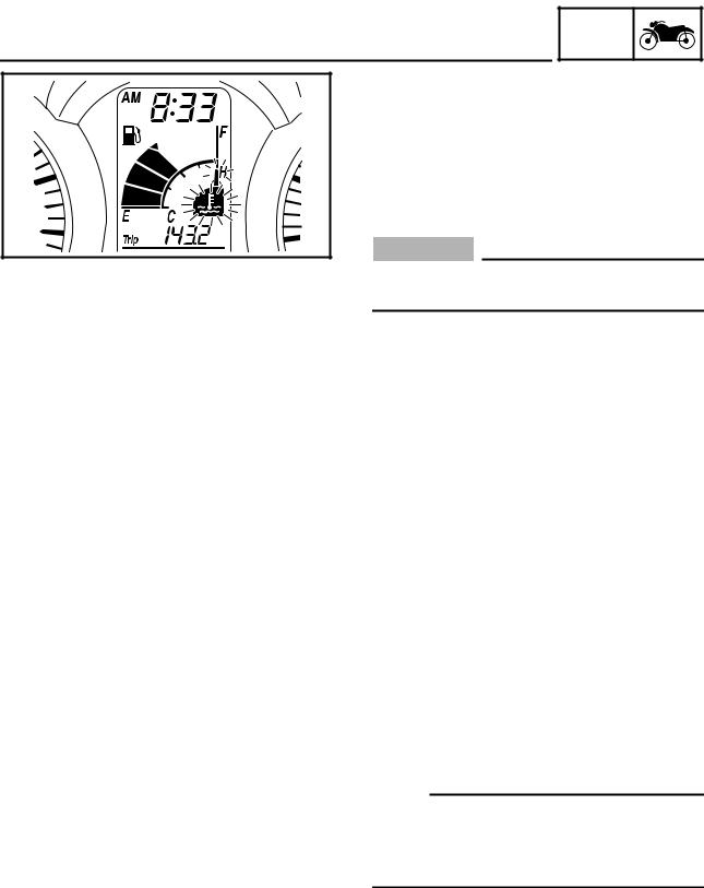
To reset the oil change indicator
1.Turn the key to “ON”.
2.Hold the reset button pushed for two to
eight seconds.
1 Reset button “OIL CHANGE”
3.Release the reset button, and the oil change indicator will go off.
NOTE:
If the engine oil is changed before the oil change indicator comes on (i.e. before the periodic oil change interval has been reached), the indicator must be reset after the oil change
|
for the next periodic oil change to be indicated |
|||
|
at the correct time. To reset the oil change |
|||
|
indicator before the periodic oil change interval |
|||
|
has been reached, follow the above proce- |
|||
. |
|
|
|
|
|
ScooterTime |
|
|
|
|
dure, but note that thenetindicator will come on |
|||
|
for 1.4 seconds after releasing the reset but- |
|||
|
ton, otherwise repeat the procedure. |
|
||
|
V-belt replacement indicator “V-BELT” |
|
||
|
This indicator flashes |
every |
20,000 |
km |
. |
V-belt |
needs to |
be |
|
|
(12,500 mi) when the |
|||
www |
|
|
|
|
|
replaced. |
|
|
|
The electrical circuit of the indicator can be checked according to the following procedure.
1.Turn the key to “ON” and make sure that the engine stop switch is set to “  ”.
”.
2.If the indicator does not come on, check the electrical circuit. Refer to “SIGNALING SYSTEM” in chapter 8.
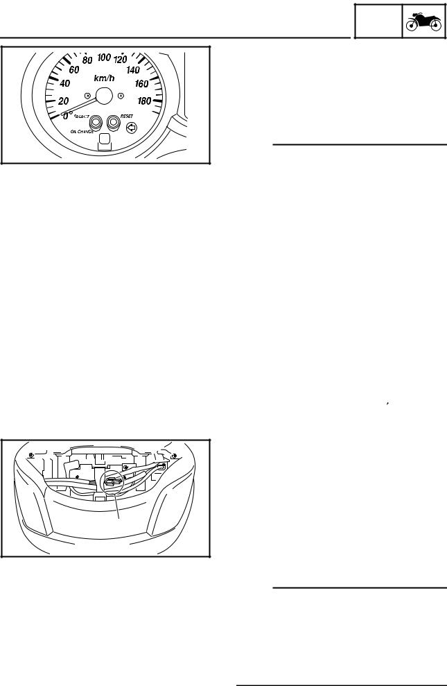
To reset the V-belt replacement indicator
1.Turn the key to “ON” and make sure that the engine stop switch is set to “ON”.
2.Disconnect the V-belt replacement reset coupler 1 for two to ten seconds.
3.And then, connect the V-belt replacement reset coupler, the V-belt replacement indicator will come on for 1.4 seconds.
And the V-belt replacement indicator will go
off.
NOTE:
If the V-belt is replaced before the V-belt replacement indicator comes on (i.e. before the V-belt replacement interval has been reached), the indicator must be reset after the V-belt replacement for the next periodic V-belt replacement to be indicated at the correct time.
1 - 7

GEN
FEATURES INFO
Self-diagnosis device
This model is equipped with a self-diagnosis device for various electrical circuits.
If any of those circuits are defective, the multifunction display will indicate a two-digit error code (e.g., 12, 13, 14).
If the multifunction display indicates an error code, note the code number, and then check the vehicle. Refer to “FUEL INJECTION SYSTEM” in chapter 7.
CAUTION:
Downloaded
from
If the multifunction display indicates an |
||
error code, the vehicle should be checked |
||
as soon as possible in order to avoid |
||
engine damage. |
|
net |
|
. |
|
ScooterTime |
|
|
Clock m de |
|
|
To set the clock: |
|
|
. |
|
|
1 Push the “SELECT” button and “RESET” |
||
button together for at least two seconds. |
||
2. When the hour digits start flashing, push |
||
www the “RESET” button to set the hours. |
||
3.Push the “SELECT” button, and the minute digits will start flashing.
4.Push the “RESET” button to set the minutes.
5.Push the “SELECT” button and then release it to start the clock. Pushing the “RESET” button for at least two seconds switches the clock display to the ambient
temperature display.
1 - 8
GEN
FEATURES INFO
Ambient temperature display
This display shows the ambient temperature from –10 °C to 50 °C in 1 °C increments. The temperature displayed may vary from the ambient temperature. Pushing the “RESET” button for at least two seconds switches the ambient temperature display to the clock display.
•When the ambient temperature falls below
–10.0 °C, “–10.0 °C” is displayed.
•When the ambient temperature climbs above 50.0 °C, “50.0” is displayed.
Downloaded |
from |
|
NOTE:
• If “– – °C” is displayed or “50.0” flashes while the ambient temperaturenet is between –10.0 °C
• The accu acy of the temperature reading may be aff cted when riding slowly (approximately under 20 km/h) or when stopped at
and 50.0 °C, there.is a problem with the elec- ScooterTimetrical circuit. Ch ck or repair the electric circuit or replace the thermistor.
traffic signals, railroad crossings, etc. . www
1 - 9

GEN
IMPORTANT INFORMATION INFO
EAS00020
IMPORTANT INFORMATION
PREPARATION FOR REMOVAL AND
DISASSEMBLY
1.Before removal and disassembly, remove all dirt, mud, dust and foreign material.
Downloaded |
from |
|
2. |
Use only the proper tools and cleaning |
||
|
equipment. |
|
|
|
Refer to “SPECIAL TOOLS”. |
||
3. |
When disassembling, always keep mated |
||
|
|
net |
|
|
parts together. This includes gears, cylin- |
||
|
. |
||
|
ders, pistons and other parts that have been |
||
ScooterTime |
|
||
|
“mated” through normal wear. Mated parts |
||
|
must always be reused or replaced as an |
||
|
assembly. |
|
|
4. |
During disassembly, clean all of the parts |
||
|
and place them in trays in the order of dis- |
||
|
assembly. This will speed up assembly and |
||
. |
|
||
www |
allow for the correct installation of all parts. |
||
Keep all parts away from any source of fire. |
|||
5. |
|||
EAS00021
REPLACEMENT PARTS
Use only genuine Yamaha parts for all replacements. Use oil and grease recommended by Yamaha for all lubrication jobs. Other brands may be similar in function and appearance, but inferior in quality.
EAS00022
GASKETS, OIL SEALS AND O-RINGS
1.When overhauling the engine, replace all gaskets, seals and O-rings. All gasket surfaces, oil seal lips and O-rings must be cleaned.
2.During reassembly, properly oil all mating parts and bearings and lubricate the oil seal lips with grease.
1 - 10

GEN
IMPORTANT INFORMATION INFO
EAS00023
LOCK WASHERS/PLATES AND COTTER PINS
After removal, replace all lock washers/plates 1 and cotter pins. After the bolt or nut has been tightened to specification, bend the lock tabs along a flat of the bolt or nut.
Downloaded |
from |
|
EAS00024
BEARINGS AND OIL SEALS
Install bearings and oil seals so that the manufacturer’s marks or numbers are visible. When
installing oil seals, lubricate the oil seal lips |
|
|
net |
with a light coat of lithium-soap-based grease. |
|
. |
|
Oil bearings liberally when installing, if appro- |
|
ScooterTime |
|
priate.
1 Oil seal
CAUTION:
Do n t spin the bearing with compressed
air because this will damage the bearing . surfaces.
www2 Bearing
EAS00025
CIRCLIPS
Before reassembly, check all circlips carefully and replace damaged or distorted circlips. Always replace piston pin clips after one use. When installing a circlip 1, make sure the sharp-edged corner 2 is positioned opposite the thrust 3 that the circlip receives.
4 Shaft
1 - 11
GEN
CHECKING THE CONNECTIONS INFO
EAS00026
CHECKING THE CONNECTIONS
Check the leads, couplers, and connectors for stains, rust, moisture, etc.
1.Disconnect:
•lead
•coupler
•connector
Downloaded |
from |
|
2. Check: |
|
|
|
• lead |
|
|
|
• coupler |
|
|
|
• connector |
|
net |
|
|
|
|
|
Moisture → Dry with an air blower. |
|||
|
|
. |
|
Rust/stains → Co ect and disconnect sev- |
|||
ScooterTime |
|
||
eral times. |
|
|
|
3. Check: |
|
|
|
• all onnections |
|
|
|
. |
|
|
|
Loose connection → Connect properly. |
|||
wwwup. |
|
|
|
NOTE: |
|
|
|
If the pin 1 on the terminal is flattened, bend it |
|||
4.Connect:
•lead
•coupler
•connector
NOTE:
Make sure all connections are tight.
5.Check:
•continuity
(with the pocket tester)
Pocket tester 90890-03112, YU-03112-C
NOTE:
•If there is no continuity, clean the terminals.
•When checking the wire harness, perform steps (1) to (3).
•As a quick remedy, use a contact revitalizer
available at most part stores.
1 - 12

SPECIAL TOOLS
EAS00027
SPECIAL TOOLS
GEN INFO
The following special tools are necessary for complete and accurate tune-up and assembly. Use only the appropriate special tools as this will help prevent damage caused by the use of inappropriate tools or improvised techniques. Special tools, part numbers or both may differ depending on the country.
When placing an order, refer to the list provided below to avoid any mistakes.
NOTE:
•For U.S.A. and Canada, use part number starting with “YM-”, “YU-”, or “ACC-”.
•For others, use part number starting with “90890-”.
Tool No. |
Tool name/Function |
|
|
Illustration |
||
|
|
|
|
|
|
|
|
Rotor holding tool |
|
|
|
|
|
90890-01235 |
|
|
|
|
. |
|
|
|
|
|
|
||
YU-01235 |
|
|
|
|
|
net |
|
|
|
|
|
|
|
|
This tool is used to hold the primary fixed |
|
|
|||
|
sheave and clutch shoe assembly. |
|
|
|
||
|
|
|
|
|
|
|
|
Ring nut wrench |
|
|
|
|
|
90890-01268 |
|
|
. |
|
|
|
YU-01268 |
|
|
|
|
||
|
|
|
|
|
||
|
|
|
|
ScooterTime |
|
|
|
This tool is used to loosen or tighten the |
|
|
|||
|
steering ring nuts. |
|
|
|
|
|
|
|
|
|
|
|
|
|
Piston pin puller set |
www |
|
|
|
|
|
|
from |
|
|
|
|
90890-01304 |
|
|
|
|
|
|
YU-01304 |
|
|
|
|
|
|
|
|
|
|
|
|
|
|
This tool is us d to remove the piston |
|
|
|||
|
pins. |
|
|
|
|
|
|
|
|
|
|
|
|
Radiator cap tester |
Radiator cap tester |
|
|
|
|
|
90890-01325 |
Radiator cap tester adapter |
|
|
|
|
|
YU-24460-01 |
|
|
|
|
|
|
Radiator cap tester |
|
|
|
|
|
|
adapter |
These tools are used to check the cooling |
|
|
|||
90890-01352 |
|
|
||||
Downloaded |
|
|
|
|
|
|
YU-33984 |
system. |
|
|
|
|
|
|
|
|
|
|
|
|
|
T-handle |
|
|
|
|
|
T-handle |
Damper rod holder |
|
|
|
|
|
90890-01326 |
|
|
|
|
|
|
Damper rod holder |
These tools are used to hold the damper |
|
|
|||
90890-01460 |
rod when removing or installing the |
|
|
|
||
|
|
|
|
|||
|
damper rod. |
|
|
|
|
|
|
|
|
|
|
|
|
|
Locknut wrench |
|
|
|
|
|
90890-01348 |
|
|
|
|
|
|
YM-01348 |
|
|
|
|
|
|
|
This tool is used to remove or install the |
|
|
|||
|
clutch shoe assembly nut. |
|
|
|
|
|
|
|
|
|
|
|
|
1 - 13

|
|
|
|
|
|
|
|
|
|
|
SPECIAL TOOLS |
|
GEN |
|
|||
|
|
|
INFO |
|
||||
|
|
|
|
|
||||
Tool No. |
Tool name/Function |
|
|
Illustration |
||||
|
|
|
|
|
|
|
|
|
Flywheel puller |
Flywheel puller |
|
|
|
|
|
|
|
Flywheel puller attachment |
|
|
|
|
|
|
|
|
90890-01362 |
|
|
|
|
|
|
|
|
Flywheel puller |
|
|
|
|
|
|
|
|
attachment |
|
|
|
|
|
|
|
|
90890-04089 |
This tool is used to remove the generator |
|
|
|
|
|
||
YM-33282 |
|
|
|
|
|
|||
rotor. |
|
|
|
|
|
|
|
|
|
|
|
|
|
|
|
|
|
|
|
|
|
|
|
|
|
|
Fork seal driver weight |
Fork seal driver weight |
|
|
|
|
|
|
|
90890-01367 |
Fork seal driver attachment (41 mm) |
|
|
|
|
|
||
YM-A9409-7 |
|
|
|
|
|
|
|
|
Fork seal driver |
These tools are used to install the oil |
|
|
|
|
|
||
attachment |
|
|
|
|
|
|||
seal, dust seal, and the outer tube bush- |
|
|
|
|
|
|||
90890-01381 |
|
|
|
|
|
|||
YM-A5142-2 |
ing of a front fork leg. |
|
|
|
|
|
|
|
|
|
|
|
|
|
|
|
|
|
Oil seal guide |
|
|
|
net |
|
|
|
90890-01396 |
|
|
ScooterTime |
|
|
|||
|
|
|
|
|
|
|||
|
This tool is used for protecting the oil seal |
. |
|
|
|
|||
|
lip when installing the secondary sliding |
|
|
|
|
|
||
|
sheave. |
|
|
|
|
|
|
|
|
|
|
|
|
|
|
|
|
|
Steering nut wrench |
|
|
|
|
|
|
|
90890-01403 |
|
|
|
|
|
|
|
|
YU-A9472 |
|
. |
|
|
|
|
|
|
|
|
|
|
|
|
|
||
|
This tool is used to loosen or tighten the |
|
|
|
|
|
||
|
steering ring nuts. |
|
|
|
|
|
|
|
|
|
|
|
|
|
|
|
|
Pivot shaft wrench |
Pivot shaft wrench |
www |
|
|
|
|
|
|
Pivot shaft wrench adapter |
|
|
|
|
|
|
||
90890-01471 |
|
|
|
|
|
|
||
YM-01471 |
|
|
|
|
|
|
|
|
Pivot shaft wrench |
Downloadedrotor and clutch housing. |
|
|
|
|
|
|
|
adapter |
These tools are usedfromto tighten the sub- |
|
|
|
|
|
||
90890-01476 |
frame adjusting bolt. |
|
|
|
|
|
|
|
|
|
|
|
|
|
|
|
|
|
|
|
|
|
|
|
|
|
|
Sheave h lder |
|
|
|
|
|
|
|
90890-01701 |
|
|
|
|
|
|
|
|
YS-01880-A |
|
|
|
|
|
|
|
|
|
This tool is used to hold the generator |
|
|
|
|
|
||
|
|
|
|
|
|
|
|
|
Compression gauge |
Compression gauge |
|
|
|
|
|
|
|
90890-03081 |
Adapter (compression gauge) |
|
|
|
|
|
|
|
YU-33223 |
|
|
|
|
|
|
|
|
Adapter (compres- |
|
|
|
|
|
|
|
|
sion gauge) |
These tools are used to measure engine |
|
|
|
|
|
||
90890-04082 |
|
|
|
|
|
|||
compression. |
|
|
|
|
|
|
|
|
|
|
|
|
|
|
|
|
|
|
|
|
|
|
|
|
|
|
|
Pocket tester |
|
|
|
|
|
|
|
90890-03112 |
|
|
|
|
|
|
|
|
YU-03112-C |
|
|
|
|
|
|
|
|
|
This tool is used to check the electrical |
|
|
|
|
|
||
|
system. |
|
|
|
|
|
|
|
|
|
|
|
|
|
|
|
|
1 - 14
|
|
|
|
|
|
|
|
SPECIAL TOOLS |
|
GEN |
|
|
|
|
|
INFO |
|
|
||
|
|
|
||||
Tool No. |
Tool name/Function |
Illustration |
||||
|
|
|
|
|
|
|
|
Timing light |
|
|
|
|
|
90890-03141 |
|
|
|
|
|
|
YU-03141 |
|
|
|
|
|
|
|
This tool is used to check the ignition tim- |
|
|
|
|
|
|
ing. |
|
|
|
|
|
|
|
|
|
|
|
|
|
Pressure gauge |
|
|
|
|
|
90890-03153 |
|
|
|
|
|
|
YU-03153 |
|
|
|
|
|
|
|
This tool is used to measure fuel pres- |
|
|
|
|
|
|
sure. |
|
|
|
|
|
|
Adapter |
|
|
net |
90890-03181 |
|
|
|
|
|
|
. |
||
YM-03181 |
|
|
||
|
|
ScooterTime |
|
|
90890-01243 |
|
|
|
|
|
This tool is used to measure fuel pres- |
|
||
|
sure. |
|
|
|
Valve spring compres- Valve spring compressor |
|
|
|
|
sor |
Valve spring compressor attachment |
|
||
90890-04019 |
|
|||
YM-04019 |
|
|
|
|
Valve spring compres- |
|
. |
|
|
sor attachment |
|
|
||
These tools are used to remove or install |
|
|||
|
|
|||
YM-01253-1 |
the valve assemblies. |
|
|
|
Middle driven shaft |
Middle driven shaft bearing driver |
|
|
|
bearing driver |
Mechanical seal installer |
www |
|
|
90890-04058 |
|
|
|
|
YM-04058 |
|
|
|
|
Mechanical seal |
Downloadedvalve guides. |
|
|
|
installer |
These tools are usedfromto install the water |
|
||
90890-04145 |
pump seal. |
|
|
|
YM-04145 |
|
|
|
|
|
Valve guide remover (5 mm) |
|
|
|
90890-04097 |
|
|
|
|
YM-04097 |
|
|
|
|
|
This tool is used to remove or install the |
|
||
Valve guide installer (5 mm)
90890-04098 YM-04098
This tool is used to install the valve guides.
Valve guide reamer (5 mm)
90890-04099 YM-04099
This tool is used to rebore the new valve guides.
1 - 15

|
|
|
|
|
|
|
|
|
|
|
|
|
SPECIAL TOOLS |
|
GEN |
|
|||
|
|
|
|
INFO |
|
||||
|
|
|
|
|
|
||||
Tool No. |
|
Tool name/Function |
|
|
Illustration |
||||
|
|
|
|
|
|
|
|
|
|
|
|
Valve lapper |
|
|
|
|
|
|
|
90890-04101 |
|
|
|
|
|
|
|
|
|
|
|
This tool is needed to remove and install |
|
|
|
|
|
||
|
|
the valve lifters. |
|
|
|
|
|
|
|
|
|
|
|
|
|
|
|
|
|
Sheave spring com- |
Sheave spring compressor |
|
|
|
|
|
|
|
|
pressor |
|
Sheave fixed block |
|
|
|
|
|
|
|
90890-04134 |
|
|
|
|
|
|
|
|
|
YM-04134 |
|
This tool is used to hold the compression |
|
|
|
|
|
||
Sheave fixed block |
|
|
|
|
|
|
|||
|
spring when removing or installing the |
|
|
|
|
|
|||
90890-04135 |
|
|
|
|
|
|
|||
YM-04135 |
|
clutch shoe assembly nut. |
|
|
|
|
|
|
|
|
|
|
|
|
|
|
|
|
|
|
|
Plane bearing installer/remover |
|
|
net |
|
|
||
90890-04146 |
|
|
|
|
|
|
|
||
|
|
|
|
. |
|
|
|
||
YM-04146 |
|
|
|
|
|
|
|
||
|
|
|
ScooterTime |
|
|
|
|
||
|
|
|
|
|
|
|
|
||
|
|
This tool is used to install or remove the |
|
|
|
|
|
||
|
|
crankshaft journal bearings. |
|
|
|
|
|
|
|
|
|
|
|
|
|
|
|
|
|
|
|
Ignition checker |
|
|
|
|
|
|
|
90890-06754 |
|
|
|
|
|
|
|
|
|
YM-34487 |
|
|
. |
|
|
|
|
|
|
|
|
|
|
|
|
|
|
||
|
|
This tool is used to check the ignition sys- |
|
|
|
|
|
||
|
|
tem components. |
|
|
|
|
|
|
|
|
|
|
|
|
|
|
|
|
|
ACC-11001-05-01 |
|
Yamaha bond No. 1215 |
|
|
|
|
|
|
|
|
This bond is used tofromseal two mating sur- |
|
|
|
|
|
|||
Bond |
|
Sealant (Quick Gasket®) |
www |
|
|
|
|
|
|
90890-85505 |
|
|
|
|
|
|
|
|
|
Sealant |
|
Downloaded |
|
|
|
|
|
|
|
|
|
|
|
|
|
|
|
|
|
|
|
faces (e.g., crankcase mating surfaces). |
|
|
|
|
|
||
|
|
|
|
|
|
|
|
|
|
1 - 16

SPEC
CHAPTER 2
SPECIFICATIONS
GENERAL SPECIFICATIONS ........................................................................ |
|
|
|
|
2-1 |
|
ENGINE SPECIFICATIONS ........................................................................... |
|
|
|
|
|
2-2 |
CHASSIS SPECIFICATIONS |
........................................................................ |
|
|
|
|
2-10 |
ELECTRICAL SPECIFICATIONS ................................................................. |
|
|
|
net |
2-14 |
|
CONVERSION TABLE |
|
|
|
|
2-17 |
|
|
|
|
|
|
||
|
|
|
|
|
. |
|
|
|
|
|
ScooterTime |
|
2-17 |
GENERAL TIGHTENING TORQUE SPECIFICATIONS |
|
|||||
TIGHTENING TORQUES .............................................................................. |
|
|
|
|
|
2-18 |
ENGINE TIGHTENING TORQUES......................................................... |
|
|
|
2-18 |
||
CHASSIS TIGHTENING TORQUES....................................................... |
|
|
|
2-21 |
||
|
|
|
. |
|
|
|
|
|
www |
|
|
2-23 |
|
LUBRICATION POINTS AND LUBRICANT TYPES .................................... |
|
|||||
ENGINE LUBRICATION POINTS AND LUBRICANT ................TYPES |
2-23 |
|||||
CHASSIS LUBRICATION POINTS AND LUBRICANT .............TYPES |
2-25 |
|||||
|
from |
|
|
|
|
2-26 |
COOLING SYSTEM DIAGRAMS .................................................................. |
|
|
|
|
||
Downloaded |
|
|
|
|
|
2-28 |
CABLE ROUTING ......................................................................................... |
|
|
|
|
|
|

GENERAL SPECIFICATIONS SPEC
SPECIFICATIONS
GENERAL SPECIFICATIONS
Item |
|
|
|
Standard |
|
|
Model code |
|
5RU4 (USA) |
|
|
||
|
|
5RUC (CDN) |
|
|
||
Dimensions |
|
|
|
|
|
|
Overall length |
|
2,230 mm (87.8 in) |
|
|
||
Overall width |
|
780 mm (30.7 in) |
|
|
||
Overall height |
|
1,380 mm (54.3 in) |
|
|
||
Seat height |
|
750 mm (29.5 in) |
|
|
||
Wheelbase |
|
1,565 mm (61.6 in) |
|
|
||
Minimum ground clearance |
|
120 mm (4.72 in) |
|
net |
||
Minimum turning radius |
|
2,600 mm (102.4 in) |
|
|||
|
|
|
||||
Weight |
|
|
|
|
. |
|
|
|
|
|
|
||
Wet (with oil and a full fuel tank) |
|
|
|
ScooterTime |
|
|
|
212 kg (467 lb) |
|
|
|||
Maximum load (total of cargo, rider, |
196 kg (432 lb) |
|
|
|||
passenger, and accessories) |
|
|
|
|
|
|
|
|
|
. |
|
|
|
|
from |
www |
|
|
|
|
Downloaded |
|
|
|
|
||
|
|
|
|
|
|
|
Limit
----
----
----
----
----
----
----
----
----
----
----
2 - 1

ENGINE SPECIFICATIONS SPEC
ENGINE SPECIFICATIONS
|
|
|
|
|
|
|
|
Item |
|
|
|
|
|
|
|
|
|
|
|
Standard |
Limit |
|||
|
|
|
|
|
|
|
|
|
|
|
|
|
|
|
|
|
|
|
|
|
|
|
|
|
Engine |
|
|
|
|
|
|
|
|
|
|
|
|
|
|
|
|
|
|
|
|
|
|
||
Engine type |
|
|
|
|
|
|
|
|
|
|
|
|
Liquid-cooled, 4-stroke, DOHC |
---- |
||||||||||
Displacement |
|
|
|
|
|
|
|
|
|
|
|
|
394.9 cm3 (24.10 cu.in) |
|
---- |
|||||||||
Cylinder arrangement |
|
|
|
|
|
|
|
|
|
Forward-inclined single cylinder |
---- |
|||||||||||||
Bore × stroke |
|
|
|
|
|
|
|
|
|
|
|
|
83.0 × 73.0 mm (3.27 × 2.87 in) |
---- |
||||||||||
Compression ratio |
|
|
|
|
|
|
|
|
|
10.6 : 1 |
|
|
---- |
|||||||||||
Engine idling speed |
|
|
|
|
|
|
|
|
|
1,300 ~ 1,500 r/min |
|
---- |
||||||||||||
Vacuum pressure at engine idling |
|
35.0 ~ 41.0 kPa |
|
---- |
||||||||||||||||||||
speed |
|
|
|
|
|
|
|
|
|
|
|
|
|
|
|
|
|
(263 ~ 308 mmHg, 10.4 ~ 12.1 inHg) |
|
|||||
Compression pressure (at sea level) |
|
|
|
net |
---- |
|||||||||||||||||||
Standard |
|
|
|
|
|
|
|
|
|
|
|
|
|
|
|
|
|
2 |
---- |
|||||
|
|
|
|
|
|
|
|
|
|
|
|
|
|
|
1,400 kPa (14.0 kg/cm2, 199.1 psi) at |
|||||||||
|
|
|
|
|
|
|
|
|
|
|
|
|
|
|
|
|
|
|
|
500 r/min |
|
. |
|
|
Minimum |
|
|
|
|
|
|
|
|
|
|
|
|
|
|
|
1,100 kPa (11.0 kg/cm |
---- |
|||||||
|
|
|
|
|
|
|
|
|
|
|
|
|
|
|
, 156.5 psi) |
|||||||||
Maximum |
|
|
|
|
|
|
|
|
|
|
|
|
|
|
|
|
|
ScooterTime |
---- |
|||||
|
|
|
|
|
|
|
|
|
|
|
|
|
|
|
1,650 kPa (16.5 kg/cm2, 234.7 psi) |
|||||||||
Fuel |
|
|
|
|
|
|
|
|
|
|
|
|
|
|
|
|
|
|
|
|
|
|
|
|
Recommended fuel |
|
|
|
|
|
|
|
|
|
Unleaded gasoline only (USA) |
---- |
|||||||||||||
|
|
|
|
|
|
|
|
|
|
|
|
|
|
|
|
|
|
|
|
Regular unleaded gasoline only (CDN) |
---- |
|||
Fuel tank capacity |
|
|
|
|
|
|
|
|
|
|
. |
|
|
|||||||||||
Total |
|
|
|
|
|
|
|
|
|
|
|
|
|
|
|
|
|
|
|
---- |
||||
|
|
|
|
|
|
|
|
|
|
|
|
|
|
|
|
|
14.0 L (3.08 Imp gal, 3.70 US gal) |
|||||||
Engine oil |
|
|
|
|
|
|
|
|
|
|
|
|
|
|
|
|
|
|
|
|
||||
Lubrication system |
|
|
|
|
|
|
|
|
|
Wet sump |
|
|
---- |
|||||||||||
Recommended oil |
|
|
|
|
|
|
|
|
from |
www |
|
|
|
|||||||||||
|
|
|
|
|
|
|
|
|
|
|
|
|
||||||||||||
0 |
10 |
30 |
50 |
70 |
90 |
|
110 130 ˚F |
|
Refer to the chart for the engine oil grade. |
---- |
||||||||||||||
|
|
|
|
|
|
|
|
|
|
|
|
|
|
|
|
|
|
|
|
|||||
|
|
|
|
|
|
|
|
|
|
|
|
|
|
|
|
|
|
|
||||||
|
|
|
|
|
|
|
|
|
|
|
|
|
|
|
|
|
|
|||||||
|
|
|
|
|
|
|
|
|
|
Downloaded |
|
|
|
|
|
|
|
|||||||
|
|
|
|
|
YAMALUBE 4 (20W40) |
|
|
|
|
|
|
|
||||||||||||
|
|
|
|
|
|
or SAE 20W40 |
|
|
|
|
|
|
|
|
|
|
|
|||||||
|
|
|
|
|
|
|
|
|
|
|
|
|
|
|
|
|
|
|
|
|
|
|
|
|
|
|
|
|
|
|
|
|
|
|
|
|
|
|
|
|
|
|
|
|
|
|
|
|
|
|
|
|
|
|
|
|
|
|
|
|
|
|
|
|
|
|||||||||
|
|
YAMALUBE 4 (10W30) |
|
|
|
|
|
|
|
|
|
|
|
|
||||||||||
|
|
or SAE 10W30 |
|
|
|
|
|
|
|
|
|
|
|
|
|
|
||||||||
–20 |
–10 |
0 |
10 |
20 |
30 |
|
40 |
50 ˚C |
|
|
|
|
|
|
||||||||||
Recommended engine oil grade |
|
API service SE, SF, SG type or higher |
---- |
|||||||||||||||||||||
Quantity |
|
|
|
|
|
|
|
|
|
|
|
|
|
|
|
|
|
|
|
|
|
|
||
Total amount |
|
|
|
|
|
|
|
|
|
|
|
|
1.70 L (1.50 Imp qt, 1.80 US qt) |
---- |
||||||||||
Without oil filter element replace- |
|
1.50 L (1.32 Imp qt, 1.59 US qt) |
---- |
|||||||||||||||||||||
ment |
|
|
|
|
|
|
|
|
|
|
|
|
|
|
|
|
|
|
|
|
|
|
||
With oil filter element replacement |
|
1.70 L (1.50 Imp qt, 1.80 US qt) |
---- |
|||||||||||||||||||||
Engine oil temperature |
|
|
|
|
|
|
70 ~ 80 °C (158 ~ 176 °F) |
---- |
||||||||||||||||
|
|
|
|
|
|
|
|
|
|
|
|
|
|
|
|
|
|
|
|
|
|
|||
Final transmission oil |
|
|
|
|
|
|
|
|
|
|
|
|
|
|
||||||||||
Type |
|
|
|
|
|
|
|
|
|
|
|
|
|
|
|
|
|
SAE10W-30 type SE motor oil |
---- |
|||||
Quantity |
|
|
|
|
|
|
|
|
|
|
|
|
|
|
|
|
|
0.25 L (0.22 Imp qt, 0.26 US qt) |
---- |
|||||
|
|
|
|
|
|
|
|
|
|
|
|
|
|
|
|
|
|
|
|
|
|
|
|
|
2 - 2
|
|
|
|
|
|
|
|
|
|
|
|
|
|
|
ENGINE SPECIFICATIONS |
|
SPEC |
|
|||
|
|
|
|
|
|
|
|
|
|
|
|
|
|
|
|
|
|
|
|
|
|
|
Item |
|
|
Standard |
|
|
|
|
Limit |
|
|
|
|
|
|
|
|
|
|
|
|
Oil pump |
|
|
|
|
|
|
|
|
||
Oil pump type |
|
Trochoid |
|
|
|
---- |
||||
Inner-rotor-to-outer-rotor-tip clear- |
|
0.07 mm |
|
|
|
0.15 mm |
||||
ance |
|
(0.0028 in) |
|
|
|
(0.0059 in) |
||||
Outer-rotor-to-oil-pump-housing |
|
0.013 ~ 0.036 mm |
|
|
|
0.106 mm |
||||
clearance |
|
(0.0005 ~ 0.0014 in) |
|
|
|
(0.0042 in) |
||||
Oil-pump-housing-to-inner-and-outer |
0.040 ~ 0.096 mm |
|
|
|
0.166 mm |
|||||
rotor clearance |
|
(0.0016 ~ 0.0038 in) |
|
|
|
(0.0065 in) |
||||
|
|
|
|
|
|
|
|
|
|
|
Cooling system |
|
|
|
|
|
|
|
|
||
Radiator capacity |
|
1.57 L (1.38 Imp qt, 1.66 US qt) |
|
---- |
||||||
Radiator cap opening pressure |
|
110.0 ~ 140.0 kPa |
|
|
|
---- |
||||
|
|
|
|
(1.10 ~ 1.40 kg/cm2, 15.6 ~ 19.9 psi) |
|
|
|
|||
Radiator core |
|
|
|
net |
|
|
|
|||
Width |
|
260 mm (10.24 in) |
. |
|
|
---- |
||||
Reduction ratio |
|
37/22 × 25/37ScooterTime(1.136) |
|
---- |
||||||
Height |
|
148 mm (5.83 in) |
|
|
|
---- |
||||
Depth |
|
24 mm (0.94 in) |
|
|
|
---- |
||||
Coolant reservoir |
|
|
|
|
|
|
|
|
||
Capacity |
|
0.32 L (0.28 Imp q , 0.34 US qt) |
|
---- |
||||||
Water pump |
|
|
|
|
|
|
|
|
||
Water pump type |
|
Single-suction centrifugal pump |
|
---- |
||||||
|
|
|
|
|
. |
|
|
|
|
|
Coolant temperature |
|
|
www |
|
|
|
---- |
|||
|
80 ~ 90 °C (176 ~ 194 °F) |
|
|
|
||||||
Starting system type |
|
Electric starter |
|
|
|
---- |
||||
Electric fuel injection |
from |
|
|
|
|
|
|
|||
|
|
|
|
|
|
|
|
|||
Type |
|
1100-87C00-A |
|
|
|
---- |
||||
Maximum warpageDownloaded |
|
---- |
|
|
|
|
0.05 mm |
|||
Manufacturer |
|
AISAN |
|
|
|
---- |
||||
Spark plug |
|
|
|
|
|
|
|
|
||
Model (manufacturer) × qu ntity |
|
CR7E (NGK) × 1 |
|
|
|
---- |
||||
Spark plug gap |
|
0.7 ~ 0.8 mm (0.028 ~ 0.031 in) |
|
---- |
||||||
Cylinder head |
|
|
|
|
|
|
|
|
||
Volume |
|
30.3 ~ 31.1 cm3 (1.85 ~ 1.90 cu.in) |
|
---- |
||||||
|
|
|
|
|
|
|
|
|
(0.002 in) |
|
|
|
|
|
|
|
|
|
|
|
|
|
|
|
|
|
|
|
|
|
|
|
|
|
|
|
|
|
|
|
|
|
|
2 - 3
ENGINE SPECIFICATIONS SPEC
Item
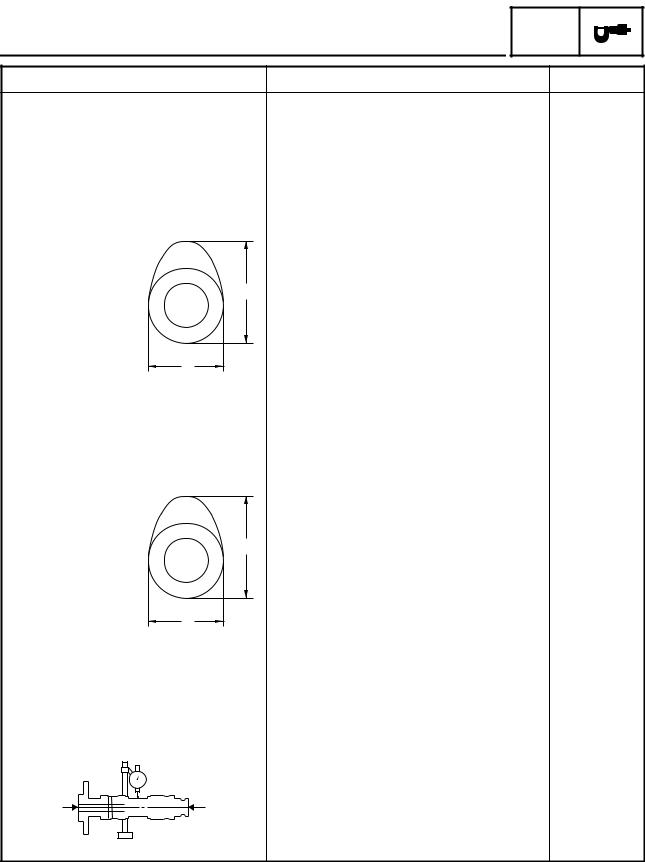
Camshafts
Drive system
Camshaft cap inside diameter Camshaft journal diameter Camshaft-journal-to-camshaft-cap clearance
Intake camshaft lobe dimensions
A
B
Measurement A
Measurement B
Exhaust camshaft lobe dimensions
A
Measurement ADownloadedB Measurement B
Maximum camshaft runout
Standard |
Limit |
Chain drive (right) |
---- |
24.500 ~ 24.521 mm (0.9646 ~ 0.9654 in) |
---- |
24.459 ~ 24.472 mm (0.9630 ~ 0.9635 in) |
---- |
0.028 ~ 0.062 mm (0.0011 ~ 0.0024 in) |
0.08 mm |
|
(0.0031 in) |
|
|
|
net |
|
|
|
. |
|
|
|
|
ScooterTime |
|
34.250 mm |
34.350 ~ 34.450 mm (1.352 ~ 1.356 in) |
||||
|
|
|
|
(1.3484 in) |
24.950 ~ 25.050 mm (0.982 ~ 0.986 in) |
24.850 mm |
|||
|
|
|
|
(0.9783 in) |
|
. |
|
|
|
from |
www |
|
|
|
|
|
|
|
|
33.450 ~ 33.550 mm (1.317 ~ 1.321 in) |
33.350 mm |
|||
|
|
|
|
(1.3130 in) |
24.956 ~ 25.056 mm (0.983 ~ 0.986 in) |
24.856 mm |
|||
|
|
|
|
(0.9786 in) |
---- |
|
|
|
0.03 mm |
|
|
|
|
(0.0012 in) |
2 - 4

|
|
|
|
|
|
|
|
|
|
|
|
|
|
|
|
|
|
|
|
|
ENGINE SPECIFICATIONS |
|
SPEC |
|
|||||
|
|
|
|
|
|
|
|
|
|
|
|
|
|
|
|
|
|
|
|
|
|
|
|
|
|
|
|
|
|
|
|
|
|
Item |
|
|
|
Standard |
|
|
|
|
|
Limit |
|
|
|
|
|
|
|
|
|
|
|
|
|
|
|
Timing chain |
|
|
|
|
|
|
|
|
|
|
|
|||
Model/number of links |
|
|
DID SCR-0409 SV/136LE |
|
|
|
|
---- |
||||||
Tensioning system |
|
|
Automatic |
|
|
|
|
---- |
||||||
|
|
|
|
|
|
|
|
|
|
|
|
|
||
Valves, valve seats, valve guides |
|
|
|
|
|
|
|
|
|
|||||
Valve clearance (cold) |
|
|
|
|
|
|
|
|
|
|
||||
|
Intake |
|
|
|
0.15 ~ 0.20 mm (0.0059 ~ 0.0079 in) |
|
---- |
|||||||
|
Exhaust |
|
|
|
0.25 ~ 0.30 mm (0.0098 ~ 0.0118 in) |
|
---- |
|||||||
Valve dimensions |
|
|
|
|
|
|
|
|
|
|
||||
|
|
|
|
|
|
B |
|
C |
|
|
|
|
|
|
|
|
A |
|
|
|
|
|
|
|
net |
|
|
D |
|
|
|
|
|
|
|
|
|
|
|
|
||||
|
|
|
|
|
|
|
|
|
|
|
|
|||
|
|
|
|
|
|
|
|
|
|
|
|
|||
Head Diameter |
|
Face Width |
|
Seat Width |
|
Margin Thickness |
||||||||
|
|
. |
|
|||||||||||
Valve seat width C |
|
|
|
|
|
|
|
|
||||||
|
|
|
|
|
|
|
|
|||||||
|
|
|
.ScooterTime |
|
|
|
|
|
||||||
Valve head diameter A |
|
|
|
|
|
|
|
|
|
|
||||
|
Intake |
|
|
|
30.9 ~ 31.1 mm (1.2165 ~ 1.2244 in) |
|
---- |
|||||||
|
Exhaust |
|
|
|
27.9 ~ 28.1 mm (1.0984 ~ 1.1063 in) |
|
---- |
|||||||
Valve face width B |
|
|
|
|
|
|
|
|
|
|
||||
|
Intake |
|
|
|
1.838 ~ 2.687 mm (0.0724 ~ 0.1058 in) |
---- |
||||||||
|
Exhaust |
|
|
|
1.697 ~ 2.828 mm (0.0668 ~ 0.1113 in) |
---- |
||||||||
|
Intake |
|
|
|
|
www |
|
|
|
|
1.6 mm |
|||
|
|
|
|
1.0 ~ 1.2 mm (0.0394 ~ 0.0472 in) |
|
|||||||||
|
|
|
|
|
|
|
|
|
|
|
|
|
(0.06 in) |
|
|
Exhaust |
|
|
|
1.0 ~ 1.2 mm (0.0394 ~ 0.0472 in) |
|
1.6 mm |
|||||||
|
|
|
|
Downloaded |
from |
|
|
|
|
|
(0.06 in) |
|||
|
|
|
|
|
|
|
|
|
|
|
||||
Valve margin thickness D |
|
|
|
|
|
|
|
|
||||||
|
Intake |
|
|
|
0.85 ~ 1.15 mm (0.0335 ~ 0.0453 in) |
|
---- |
|||||||
|
Exhaust |
|
|
|
0.85 ~ 1.15 mm (0.0335 ~ 0.0453 in) |
|
---- |
|||||||
Valve stem diameter |
|
|
|
|
|
|
|
|
|
|
||||
|
Intake |
|
|
|
4.975 ~ 4.990 mm (0.1959 ~ 0.1965 in) |
4.945 mm |
||||||||
|
|
|
|
|
|
|
|
|
|
|
|
|
(0.1947 in) |
|
|
Exhaust |
|
|
|
4.960 ~ 4.975 mm (0.1953 ~ 0.1959 in) |
4.930 mm |
||||||||
|
|
|
|
|
|
|
|
|
|
|
|
|
(0.1941 in) |
|
Valve guide inside diameter |
|
|
|
|
|
|
|
|
|
|
||||
|
Intake |
|
|
|
5.000 ~ 5.012 mm (0.1969 ~ 0.1973 in) |
5.050 mm |
||||||||
|
|
|
|
|
|
|
|
|
|
|
|
|
(0.1988 in) |
|
|
Exhaust |
|
|
|
5.000 ~ 5.012 mm (0.1969 ~ 0.1973 in) |
5.050 mm |
||||||||
|
|
|
|
|
|
|
|
|
|
|
|
|
(0.1988 in) |
|
Valve-stem-to-valve-guide clearance |
|
|
|
|
|
|
|
|
||||||
|
Intake |
|
|
|
0.010 ~ 0.037 mm (0.0004 ~ 0.0015 in) |
0.080 mm |
||||||||
|
|
|
|
|
|
|
|
|
|
|
|
|
(0.0031 in) |
|
|
Exhaust |
|
|
|
0.025 ~ 0.052 mm (0.0010 ~ 0.0020 in) |
0.100 mm |
||||||||
|
|
|
|
|
|
|
|
|
|
|
|
|
(0.0039 in) |
|
|
|
|
|
|
|
|
|
|
|
|
|
|
|
|
2 - 5
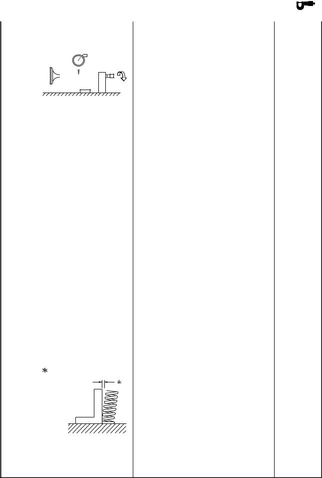
|
|
|
|
|
|
|
|
|
|
|
|
|
|
|
|
|
|
|
|
|
|
|
|
|
|
|
|
|
|
|
|
|
|
ENGINE SPECIFICATIONS |
|
SPEC |
|
|
|
|
|
|
|
|
|
|
|
|
|
|
|
|
|
|
|
|
|
|
|
|
|
|
|
|
|
|
|
|
|
|
|
|
|
|
|
|
|
|
|
|
|
|
Item |
|
|
|
|
|
|
|
|
Standard |
|
|
Limit |
||||
|
|
|
|
|
|
|
|
|
|
|
|
|
|
|
|
|
|||
Valve stem runout |
---- |
|
0.01 mm |
|
|||||||||||||||
|
|
|
|
|
|
|
|
|
|
|
|
|
|
|
|
(0.0004 in) |
|||
|
|
|
|
|
|
|
|
|
|
|
|
|
|
|
|
||||
|
|
|
|
|
|
|
|
|
|
|
|
|
|
|
|
|
|
|
|
|
|
|
|
|
|
|
|
|
|
|
|
|
|
|
|
|
|
|
|
|
|
|
|
|
|
|
|
|
|
|
|
|
|
|
|
|
|
|
|
|
|
|
|
|
|
|
|
|
|
|
|
|
|
|
|
|
|
|
|
Valve seat width |
|
|
|
|
|
|
|
|
|
Intake |
|
|
1.0 ~ 1.2 mm (0.0394 ~ 0.0472 in) |
1.6 mm |
|||||
|
|
|
|
|
|
|
|
(0.06 in) |
|
Exhaust |
|
|
1.0 ~ 1.2 mm (0.0394 ~ 0.0472 in) |
1.6 mm |
|||||
|
|
|
|
|
|
|
|
(0.06 in) |
|
|
|
|
|
|
|
|
|
|
|
Valve springs |
|
|
|
|
|
|
|
|
|
Free length |
|
|
|
|
|
ScooterTime |
|
||
Intake |
|
|
|
|
|
44.13 mm |
|||
|
|
46.45 mm (1.83 in) |
.net |
||||||
|
|
|
|
|
|
|
|
(1.74 in) |
|
Exhaust |
|
|
46.45 mm (1.83 in) |
|
44.13 mm |
||||
|
|
|
|
|
|
|
|
(1.74 in) |
|
Installed length (valve closed) |
|
|
|
|
|
|
|
||
Intake |
|
|
35.10 mm (1.38 in) |
|
---- |
||||
Exhaust |
|
|
|
|
. |
|
---- |
||
|
|
35.10 mm (1 38 in) |
|
||||||
Spring rate (K1) |
|
|
|
www |
|
|
|
||
|
|
|
|
|
|
|
|
||
Intake |
|
|
15.21 |
N/mm (1.55 kg/mm, 86.77 lb/in) |
---- |
||||
Exhaust |
|
|
from |
|
N/mm (1.55 kg/mm, 86.77 lb/in) |
---- |
|||
|
|
15.21 |
|||||||
Spring rate (K2) |
|
|
|
|
|
|
|
|
|
Intake |
Downloaded |
19.84 |
N/mm (2.02 kg/mm, 113.28 lb/in) |
---- |
|||||
Exhaust |
19.84 |
N/mm (2.02 kg/mm, 113.28 lb/in) |
---- |
||||||
|
|
||||||||
Compressed spring force (inst |
lled) |
|
|
|
|
|
|
||
Intake |
|
|
160.5 |
~ 184.7 N at 35.10 mm |
---- |
||||
|
|
|
(16.37 ~ 18.83 kg at 35.10 mm, |
|
|||||
|
|
|
36.08 |
~ 41.52 lb at 1.38 in) |
|
|
|||
Exhaust |
|
|
160.5 |
~ 184.7 N at 35.10 mm |
---- |
||||
|
|
|
(16.37 ~ 18.83 kg at 35.10 mm, |
|
|||||
|
|
|
36.08 |
~ 41.52 lb at 1.38 in) |
|
|
|||
Spring tilt |
|
|
|
|
|
|
|
|
|
Intake |
---- |
2.0 mm |
|
|
(0.08 in) |
Exhaust |
---- |
2.0 mm |
|
|
(0.08 in) |
2 - 6
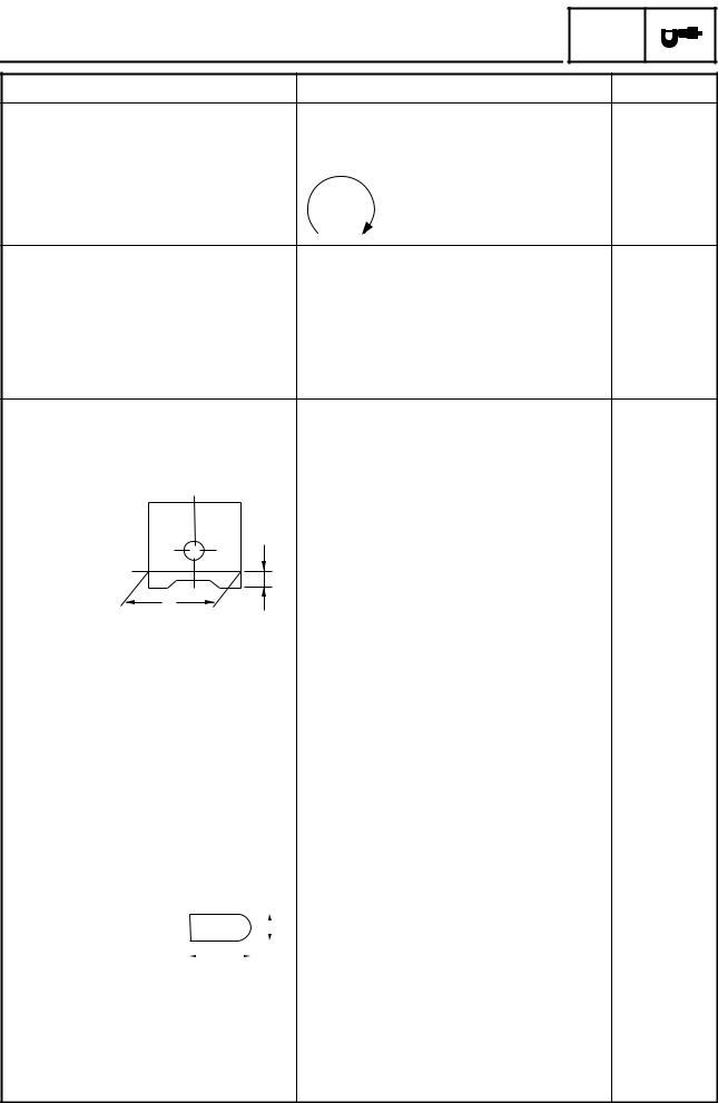
ENGINE SPECIFICATIONS SPEC
Item |
Standard |
Winding direction (top view) |
|
Intake |
Clockwise |
Exhaust |
Clockwise |
Cylinder |
|
|
|
|
|
|
|
|
|
|
|
Cylinder arrangement |
|
Forward-inclined single cylinder |
|||||||||
Bore × stroke |
|
|
|
|
|
|
|
|
83.0 × 73.0 mm (3.27 × 2.87 in) |
||
Compression ratio |
|
10.6 : 1 |
|
||||||||
Bore |
|
|
|
|
|
|
|
|
83.000 ~ 83.010 mm (3.2677 ~ 3.2681 in) |
||
Maximum taper |
|
|
|
|
|
|
|
|
---- |
|
.net |
Piston |
|
|
|
|
|
|
|
|
|
|
|
Piston-to-cylinder clearance |
|
|
|
ScooterTime |
|||||||
|
0.060 ~ 0.075 mm (0.0024 ~ 0.0030 in) |
||||||||||
Diameter D |
|
|
|
|
|
|
|
|
82.930 ~ 82.945 mm (3.2650 ~ 3.2656 in) |
||
|
|
|
|
|
|
|
|
|
|
. |
|
|
|
|
|
|
|
|
|
|
|
||
|
|
|
|
|
|
|
|
|
|
||
|
|
|
|
|
|
|
H |
|
www |
|
|
|
|
|
|
|
|
|
|
|
|
||
|
D |
from |
|
|
|||||||
|
|
|
|
|
|||||||
Height H |
|
|
|
|
|
|
|
|
5.0 mm (0.20 in) |
||
Piston pin bore (in the piston) |
|
|
|
|
|||||||
Diameter |
Downloaded |
|
20.004 ~ 20.015 mm |
||||||||
|
|
|
|
|
|
|
|
||||
|
|
|
|
|
|
|
|
|
(0.7876 ~ 0.7880 in) |
||
Offset |
|
|
|
|
|
|
|
|
1.0 mm (0.0394 in) |
||
Offset direction |
|
|
|
|
|
|
|
|
Intake side |
|
|
Piston pin |
|
|
|
|
|
|
|
|
|
|
|
Outside diameter |
|
19.991 ~ 20.000 mm |
|||||||||
|
|
|
|
|
|
|
|
|
(0.7870 ~ 0.7874 in) |
||
Piston-pin-to-piston-pin-bore clear- 0.004 ~ 0.024 mm (0.0002 ~ 0.0009 in) |
|||||||||||
ance |
|
|
|
|
|
|
|
|
|
|
|
Piston rings |
|
|
|
|
|
|
|
|
|
|
|
Top ring |
|
|
|
|
|
|
|
|
|
|
|
|
|
|
|
|
|
|
|
|
|
|
|
|
|
|
|
|
|
|
|
B |
|
|
|
Ring type |
|
T |
|
|
|
|
Barrel |
|
|||
|
|
|
|||||||||
|
|
|
|
|
|
|
|
|
|||
|
|
|
|
|
|
|
|
|
|||
Dimensions (B × T) |
|
1.00 × 2.70 mm (0.04 × 0.11 in) |
|||||||||
End gap (installed) |
|
0.20 ~ 0.35 mm (0.0079 ~ 0.0138 in) |
|||||||||
Ring side clearance |
|
0.030 ~ 0.070 mm (0.0012 ~ 0.0028 in) |
|||||||||
Limit
----
----
----
----
----
----
0.05 mm
(0.002 in)
0.15 mm
(0.0059 in)
----
----
20.045 mm
(0.7892 in)
----
----
19.971 mm
(0.7863 in)
0.074 mm
(0.0029 in)
----
----
0.50 mm
(0.0197 in)
0.100 mm
(0.0039 in)
2 - 7
 Loading...