


FTDX9000 Contest
Operation Manual
GENERAL DESCRIPTION
We wish to take this opportunity to thank you for your purchase of the FT DX 9000 Series Transceiver!
The FT DX 9000 is the culmination of a four-year design project. But it also is the product of our company’s fifty years of engineering, design, and manufacturing know how. As pioneers in the development of SSB, we have led the technological advances in Amateur Radio communications over the last half century. And now, with the introduction of the FT DX 9000 Series, we again lead the way with a no-compromise 21st-century design that will make your operating dreams come true. More importantly, it is a radio that will let your skills and experience find expression, as you harness the excitement of HF operating like you’ve never done before!
ABOUT THIS MANUAL. . .
The FT DX 9000 Series is a leading-edge transceiver with a number of new and exciting features, some of which may be unfamiliar to you. In order to gain the most enjoyment and operating efficiency from your FT DX 9000, we recommend that you read this manual in its entirety, and keep it handy for reference as you explore the many capabilities of your new transceiver.
Before using your FT DX 9000, be sure to read and follow the instructions in the “Before You Begin” section of this manual.
CONVENTIONS USED IN THIS MANUAL
Please note the conventions, described below, for operational commands and texts included in this manual.
(# ) ..... |
This refers to a switch or knob used for controlling a particular function. The name or number inside the |
|
|
brackets designate the name of the switch/knob, or its reference number within this manual. |
|
XX ........... |
In the texts, you may be advised to press a button momentarily, or press and hold it in for a time interval (such |
|
|
as two seconds). Please be sure to observe the proper procedure when pressing a button. |
|
OO ........... |
This indicates the pressing of a button when a “momentary” press is the only selection available. |
|
Note ......................................... |
|
This is used for a note as to a particular point of interest. |
Advice ..................................... |
|
This is used to amplify or expand on instructions, so as to recommend a way to gain |
|
|
maximum benefit from a feature or function. |
Example .................................. |
|
This is used to demonstrate an example of how a feature or function should work or be |
|
|
programmed. |
Quick Note / Quick Point |
This is used for a brief explanation of a particular aspect of operation. |
|
Terminology ........................... |
An explanation of a term or expression used in this manual. |
|
FT DX 9000 CONTEST OPERATION MANUAL |
Page 1 |

TABLE OF CONTENTS
General Description ........................................... |
1 |
About This Manual. . . ........................................................................ |
1 |
Conventions Used in This Manual ...................................................... |
1 |
Before You Begin. . . ........................................... |
4 |
1. Connecting AC Power ..................................................................... |
4 |
2. Configuring Your FT DX 9000 Using the Menu ............................ |
4 |
3. Connecting and Selecting the Microphone ..................................... |
5 |
4. Extending the Front Feet ................................................................. |
5 |
5. Adjusting the Main Dial Torque ..................................................... |
6 |
6. Restarting Power after a Voltage Fluctuation .................................. |
6 |
7. Resetting the Microprocessor .......................................................... |
7 |
Resetting Memories (Only) .......................................................... |
7 |
Menu Resetting ............................................................................ |
7 |
Full Reset ...................................................................................... |
7 |
Features .............................................................. |
8 |
Accessories ...................................................... |
10 |
Options .............................................................. |
11 |
Installation and Interconnections .................... |
12 |
Antenna Considerations .................................................................... |
12 |
About Coaxial Cable ......................................................................... |
12 |
Grounding .......................................................................................... |
13 |
Connection of Antenna and Power Cables ........................................ |
14 |
Connection of Microphone, Headphones and |
|
FH-2 Remote Control Keypad ............ |
15 |
Key, Keyer, and Computer-Driven Keying Interconnections ........... |
16 |
VL-1000 Linear Amplifier Interconnections .................................... |
17 |
Interfacing to Other Linear Amplifiers .............................................. |
18 |
Plug/Connector Pinout Diagrams ................... |
19 |
Front Panel Controls ........................................ |
20 |
Rear Panel ......................................................... |
34 |
Frequency Display ............................................ |
36 |
FH-2 Operation ................................................. |
37 |
Basic Operation: |
|
Receiving on Amateur Bands ......... |
38 |
Operation ........................................................................................... |
39 |
Operation on 60-Meter (5 MHz) Band (U.S. Version only) ............. |
41 |
CLAR (Clarifier) Operation on Main (VFO-A) ................................ |
42 |
LOCK ................................................................................................ |
43 |
DIM ................................................................................................... |
43 |
B-DISP OFF ...................................................................................... |
43 |
Convenient Features ........................................ |
44 |
P.BACK (Audio Playback) from VFO-A Receiver ........................... |
44 |
"MY Bands" Operation ..................................................................... |
45 |
Band Stack Operation ....................................................................... |
46 |
C.S (Custom Switch) ......................................................................... |
46 |
Rotator Control Functions ................................................................. |
47 |
More Frequency Navigation Techniques .......................................... |
48 |
ANTENNA SELECTION .................................................................. |
49 |
Receiver Operation (Front End Block Diagram) .............................. |
50 |
IPO (Intercept Point Optimization) ................................................... |
51 |
ATT .................................................................................................... |
52 |
RF Gain (SSB/CW/AM Modes) ....................................................... |
53 |
Advanced Interference |
|
-Suppression Features .................. |
54 |
Using the VRF (Variable RF Front-end Filter) ................................. |
54 |
Interference Rejection ...................................... |
55 |
ROOFING (Roofing Filters) ............................................................. |
55 |
Contour Control Operation ............................................................... |
56 |
IF SHIFT Operation (SSB/CW/RTTY/PKT Modes) ......................... |
57 |
WIDTH (IF DSP Bandwidth) Tuning |
|
(SSB/CW/RTTY/PKT Modes) ........................ |
58 |
Using IF Shift and Width Together ............................................ |
58 |
IF Notch Filter Operation (SSB/CW/RTTY/PKT/AM Modes) ........ |
59 |
Digital Noise Reduction (DNR) Operation ....................................... |
60 |
NARROW (NAR) One-Touch IF Filter Selection ............................ |
61 |
Digital Notch Filter (D.NOTCH) Operation ..................................... |
62 |
IF Noise Blanker (NB) Operation ..................................................... |
62 |
Tools for Comfortable and |
|
Effective Reception................... |
63 |
AGC (Automatic Gain Control) ........................................................ |
63 |
SLOPED AGC Operation ........................................................... |
64 |
Audio Limiter (AFL) Feature ............................................................ |
65 |
SSB/AM Mode Transmission ........................... |
66 |
Phantom Voltage for Condenser Microphones ................................. |
67 |
Using the Automatic Antenna Tuner ............... |
68 |
ATU Operation .................................................................................. |
68 |
About ATU Operation ....................................................................... |
69 |
Lithium Battery Replacement ........................................................... |
70 |
SSB/AM Mode Transmission ........................... |
72 |
Using the Speech Processor - SSB, AM Mode - ............................ |
72 |
Adjusting the SSB Transmitted Bandwidth ...................................... |
73 |
Signal Quality Enhancement Using the |
|
Parametric Microphone Equalizer ................................... |
74 |
LowDistortion CLASS-A Operation ............................................... |
76 |
Voice Memory ................................................................................... |
78 |
Convenient Transmitter Accessories .............. |
80 |
VOX: Automatic TX/RX Switching using Voice Control |
|
SSB/AM/FM Modes ............. |
80 |
Using the MONITOR ........................................................................ |
80 |
Split Operation Using the TX Clarifier (VFO-A Operation) ........... |
81 |
Clarifier Offset Bar Indicator ..................................................... |
81 |
Split-Frequency Operation ................................................................ |
82 |
Quick Split Operation ................................................................ |
83 |
CW Mode Operation ......................................... |
84 |
Setup for Straight Key (and Straight Key emulation) Operation ...... |
84 |
Using the Built-in Electronic Keyer .................................................. |
85 |
Full Break-in (QSK) Operation ......................................................... |
85 |
Setting the Keyer Weight (Dot/Space:Dash ) Ratio .......................... |
86 |
Selecting the Keyer Operating Mode ................................................ |
86 |
CW Convenience Features .............................. |
87 |
CW Spotting (Zero-Beating) ............................................................. |
87 |
Using CW Reverse ............................................................................ |
88 |
CW Delay Time Setting .................................................................... |
89 |
CW Pitch Adjustment ........................................................................ |
89 |
Contest Memory Keyer ..................................................................... |
90 |
Message Memory ....................................................................... |
90 |
TEXT Memory ........................................................................... |
92 |
Page 2 |
FT DX 9000 CONTEST OPERATION MANUAL |

TABLE OF CONTENTS
FM Mode Operation .......................................... |
94 |
Operation ..................................................................... |
94 |
Repeater Operation ...................................................... |
95 |
Convenient Memory Functions ....................... |
96 |
QMB (Quick Memory Bank) ............................. |
97 |
QMB Channel Storage ...................................................................... |
97 |
QMB Channel Recall ........................................................................ |
97 |
Memory Groups ................................................ |
98 |
Memory Group Assignment .............................................................. |
98 |
Choosing the Desired Memory Group .............................................. |
98 |
Memory Operation ............................................ |
99 |
Memory Storage ................................................................................ |
99 |
Memory Channel Recall .................................................................... |
99 |
Checking a Memory Channel’s Status ..................................... |
100 |
Erasing Memory Channel Data ....................................................... |
100 |
Moving Memory Data to the Main (VFO-A) Band ........................ |
101 |
Memory Tune Operation .......................................................... |
101 |
Operation on Alaska Emergency Frequency: |
|
5167.5 kHz (U.S. Version Only) ............. |
102 |
Operation on the 60-Meter Band (U.S. Version) ............................ |
103 |
VFO and Memory Scanning ........................... |
104 |
VFO Scanning ................................................................................. |
104 |
Memory Scan .................................................................................. |
104 |
PMS ................................................................. |
105 |
Packet Operation ............................................ |
106 |
RTTY (Radio TeleType) Operation ................. |
107 |
Miscellaneous AFSK-based Data Modes ...... |
108 |
About the Transverter Output Terminal ........ |
109 |
Menu Mode ..................................................... |
110 |
Using the Menu ............................................................................... |
110 |
Menu Mode Reset .................................................................... |
110 |
Menu Mode Setting Table ................................................................ |
111 |
Menu Mode Setting ......................................................................... |
115 |
Customized Option ........................................ |
133 |
About Customized Option .............................................................. |
133 |
Dual Receive Unit (RXU-9000) ....................... |
134 |
Front Panel Controls ........................................................................ |
134 |
Dual Receive ................................................................................... |
136 |
Dial Swap Configuration (AF/RF GAIN Controls) ........................ |
115 |
Changing the Speaker Output Configuration ................................. |
141 |
Adjacent Channel Monitor (ACM) -- CW Mode Only -- ............... |
142 |
RF Gain -- SSB/CW/AM Modes -- ................................................. |
143 |
Using the VRF (Variable RF Front-end Filter) ............................... |
144 |
ROOFING/R.FLT (Roofing Filters) ................................................ |
145 |
CONTOUR/CONT (Contour) Control Operation ........................... |
146 |
IF SHIFT Operation -- SSB/CW/RTTY/PKT Modes -- .................. |
147 |
WIDTH (IF DSP Bandwidth) Tuning |
|
-- SSB/CW/RTTY/PKT Modes -- ............................. |
148 |
IF Notch Filter Operation -- SSB/CW/RTTY/PKT/AM Modes -- |
. 149 |
NR/DNR (Digital Noise Reduction) Operation .............................. |
150 |
Digital Notch Filter (DNF) Operation ............................................. |
151 |
IF Noise Blanke (NB) Operation .................................................... |
152 |
AGC (Automatic Gain Control) ...................................................... |
153 |
Mute Feature -- VFO-A -- ............................................................... |
153 |
Audio Limiter (AFL) Feature .......................................................... |
154 |
ATT .................................................................................................. |
154 |
RF μ-Tuning Units |
|
(MTU-160, MTU-80/40, MTU-30/20) .......... |
156 |
Optional Data Management Unit (DMU-9000)/ |
|
TFT Display Unit (TFT-9000) .......... |
158 |
Front Panel Controls ........................................................................ |
158 |
TFT Feature / Control Details ......................................................... |
160 |
Rear Panel Connections .................................................................. |
161 |
Connecting a GPS Receiver ............................................................ |
161 |
Specifications ................................................. |
162 |
FT DX 9000 CONTEST OPERATION MANUAL |
Page 3 |
Before You Begin. . .
1. Connecting AC Power
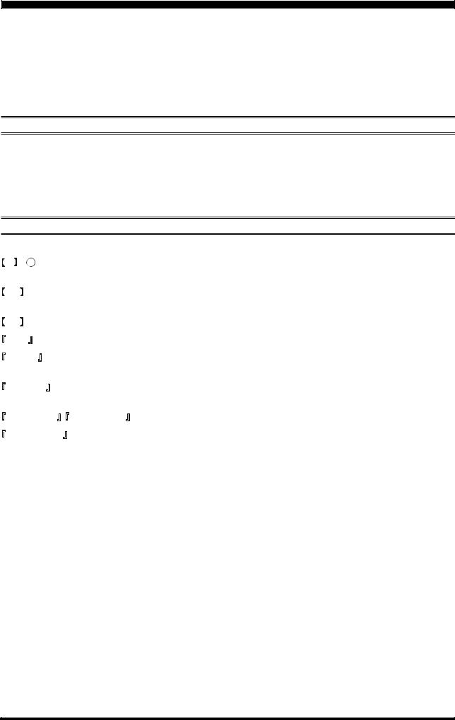
There are two power switches on this transceiver, one each on the rear and front panels. If the rear panel’s Power switch is not turned on, the front panel Power switch will not function.
Push the rear panel’s Power switch to the I position to apply power from the power supply to the OCXO (Reference Crystal Oven) and to enable the front panel power switch.
Press and hold in the front panel Power switch for two seconds to turn the transceiver on.
Note
The self-check function of the CPU inside the radio will begin. Then, if the optional RF μ-Tuning Unit is installed, the μ-Tuning circuitry will receive the data from the CPU and it will perform its own self-check, and will preset itself to the proper settings for the current operating frequency.
While the μ-Tuning circuitry is obtaining the data, the drive mechanism will move from one end of its range to the other end (fast), and this will cause a temporary “motor” noise that can be heard; this, does not represent any trouble or problem.
When the optional μ-Tuning Unit and/or the Data Management Unit are installed, the initialization process for the transceiver will take about 10 seconds, after which operation may begin.
2. Configuring Your FT DX 9000 Contest Using the Menu
The FT DX 9000 Contest is configured, at the factory, with its various functions set up in a manner typical for most operation. Via the “Menu” system, you may change these settings to match the way you want your transceiver to operate.
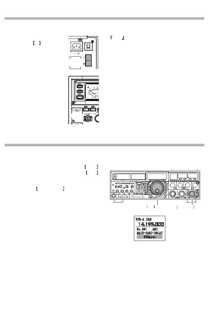
Menu programming is enabled by pressing the MNU (Menu) key momentarily. You may then rotate the Main Tuning Dial to display the desired Menu item, in the menu list, on the LCD. Each of the settings can be changed or customized via the CLAR/VFO-B knob, as you like, in this mode.
Once you have made a change to the configuration of a Menu item or items, you must press and hold in the  MNU
MNU (Menu) key for two seconds to save the new settings and exit to normal operation.
If you wish to cancel a change to a Menu item or items, just press the MNU
MNU key momentarily. If you do not press and hold in the
 MNU
MNU key in for two seconds, any changes you have made will not be saved.
 MNU
MNU key
key
Main Tuning Dial |
CLAR/VFO-B Knob |
 MENU ITEM
 MENU SETTING
Page 4 |
FT DX 9000 CONTEST OPERATION MANUAL |
Before You Begin. . .
3. Connecting and Selecting the Microphone
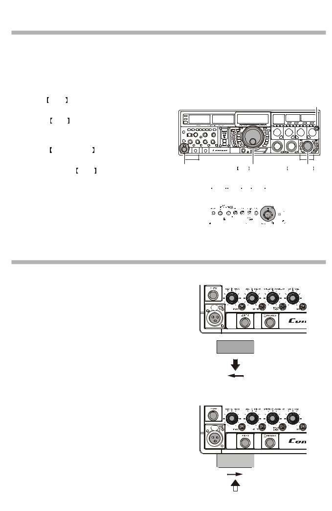
The FT DX 9000 Contest comes equipped with two microphone connectors: the front panel includes a “Cannon” (XLR) three-pin connector, while the rear panel provides an eight-pin (round) connector.
As shipped from the factory, the front panel XLR connector is engaged for operation, and the rear panel 8-pin microphone jack is not connected. If you wish to enable the 8-pin connector instead of the XLR connector, use the Menu to accomplish this. Note that you may leave microphones connected to both jacks, and may select the microphone you want for operation on a particular operating mode (SSB, AM, FM, etc.), as well!
Press the MNU (Menu) key momentarily to enter the Menu Mode.
Rotate the Main Tuning Dial to select Menu Item #069, located within the “MODE SSB” group: SSB MIC SELECT.
Rotate the CLAR/VFO-B knob to change the setting of Menu #069 from “FRONT” to “REAR.”
Press and hold in the MNU (Menu) key for two seconds to save the new setting and exit to normal operation.
In a similar manner, you may use Menu #040 (AM MIC SELECT) in the MODE-AM Menu Group to select the microphone jack to be used during AM operation, and Menu #059 (FM MIC SELECT) in the MODE-FM Menu Group to select the microphone to be used during FM transmission.
 MNU
MNU key
key
“FRONT” |
|
|
Main Tuning Dial |
|
|
|
|
CLAR/VFO-B Knob |
|||||||||||||
Cannon (XLR) |
|
|
|
|
|
|
|
|
|
|
|
|
|
|
|
||||||
three-pin connector |
|
|
|
|
|
|
|
|
|
|
|
|
|
|
|
||||||
|
|
|
|
|
|
|
|
|
|
|
|
|
|
|
|
|
|
|
|
|
|
|
|
|
|
|
|
|
|
|
|
|
|
|
|
|
|
|
|
|
|
|
|
|
|
|
|
|
|
|
|
|
|
|
|
|
|
|
|
|
|
|
|
|
|
|
|
|
|
|
|
|
|
|
|
|
|
|
|
|
|
|
|
|
|
|
|
|
|
|
|
|
|
|
|
|
|
|
|
|
|
|
|
|
|
|
|
|
|
|
|
|
|
|
|
|
|
|
|
|
|
|
|
|
|
|
|
|
|
|
|
“REAR”
8-pin microphone jack
4. Extending the Front Feet
In order to elevate the front panel for easy viewing, the front left and right feet of the bottom case may be extended.
Pull the front legs outward from the bottom panel.
Rotate the legs counter-clockwise to lock them in the extended position. Be sure the legs have locked securely in place, because the transceiver is quite heavy and an unlocked leg could result in damage, should the transceiver move suddenly.
EXTEND
Retracting the Front Feet
Rotate the legs clockwise, and push them inward while rotating to the right.
The front feel should now be locked in the retracted position.
RETRACT
FT DX 9000 CONTEST OPERATION MANUAL |
|
Page 5 |
|

Before You Begin. . .
5. Adjusting the Main Dial Torque
The torque (drag) of the Main Tuning Dial may be adjusted according to your preferences. Simply hold down the rear skirt of the knob, and while holding it in place rotate the Main Dial itself to the right to reduce the drag, or to the left to increase the drag.
HOLD THE SKIRT
TIGHTEN |
TOOSEN |
6. Restarting Power after a Voltage Fluctuation
If your AC mains power should suffer a significant fluctuation or interruption, we recommend that you go through a complete power-up cycle, in order to ensure that all circuits are properly initialized. To do this, be sure the front panel Power switch is turned off, then set the rear-panel Power switch to the “O” position. Now unplug the AC cable from the rear panel of the transceiver, and wait ten seconds. Plug the AC cable back in, set the rear-panel Power switch to “O,” and now press and hold in the front-panel Power switch for two seconds to turn the transceiver on. After about 50 seconds, all circuits will be initialized, and normal operation may resume.
Page 6 |
FT DX 9000 CONTEST OPERATION MANUAL |
Before You Begin. . .
7. Resetting the Microprocessor
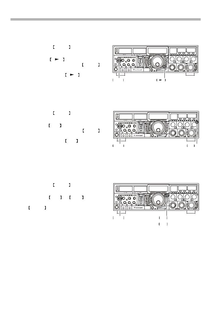
Resetting Memories (Only)
Use this procedure to reset (clear out) the Memory channels previously stored, without affecting any configuration changes you may have made to the Menu settings.
1.Press the front panel’s POWER switch to turn the transceiver off.
2. Press and hold in the A M switch; while holding it in, press and hold in the front panel’s POWER switch to turn the transceiver on. Once the transceiver comes on, you may release the A M switch.
POWER switch |
A M switch |
Menu Resetting
Use this procedure to restore the Menu settings to their factory defaults, without affecting the memories you have programmed.
1.Press the front panel’s POWER switch to turn the transceiver off.
2. Press and hold in the MNU (Menu) key; while holding it in, press and hold in the front panel’s POWER switch to turn the transceiver on. Once the transceiver comes on, you may release the MNU (Menu) key.
POWER switch |
MNU key |
Full Reset
Use this procedure to restore all Menu and Memory settings to their original factory defaults. All Memories will be cleared out by this procedure.
1.Press the front panel’s POWER switch to turn the transceiver off.
2. Press and hold in the FAST and LOCK switches; while holding them in, press and hold in the front panel’s POWER switch to turn the transceiver on. Once the transceiver comes on, you may release the other two switches.
POWER switch |
FAST |
switch |
|
& |
|
|
LOCK |
switch |
FT DX 9000 CONTEST OPERATION MANUAL |
Page 7 |

FEATURES
Superior Visibility and Logical, Fatigue-reducing Panel Layout
The front panel layout is logically crafted, with the large-aperture main frequency display squarely in the middle of the front panel; the two large S-meters to the left providing instant recognition of signal strength.
Just as in an aircraft cockpit, the panel meters and the LCD are canted slightly toward the center for maximum visibility.
Large, Multi-colored VFD Fluorescent Display
A proprietary, high-brightness VFD (fluorescent) display is incorporated in the FT DX 9000 Series, providing outstanding visibility and easy reading of the important frequency information, whether in dim or bright lighting environments.
Function-Indicating LEDs
The many function status indications on the front panel are clearly identified by the operator, thanks to the innovative multi-color LEDs incorporated in design. A Red LED indicates that a function is engaged on the VFO-A, while an Orange LED shows that the function is engaged on the VFO-B.
Indirect Illumination
To assist with operation in a dark environment, indirect illumination of the front panel’s knobs and switches is provided via lamps installed beneath the meters and the  BAND
BAND switch.
Aluminum-Die-Cast Oversized Main Tuning Dial
The Main Tuning Dial is a large-diameter (3.2”/81 mm) dial directly coupled to the magnetic rotary encoder which drives the HRDDS via microprocessor control. Its heavy weight (7 oz./200 g) and quality mounting and construction provide a smooth “flywheel” effect during operation, ideal for quick cruising up and down a band.
Oversized Knobs for Most Important Functions
The concentric AF/RF Gain, SHIFT/WIDTH, and CLAR/VFO-B knobs are conveniently located at the right-bottom side of the Front Panel, for ease of access to these important controls.
World’s First 400 MHz HRDDS Local Oscillator
So as to optimize spurious-free dynamic range in a multi-signal environment, Yaesu’s engineers have introduced the world’s first HRDDS (High Resolution Direct Digital Synthesizer) as the first local oscillator of the FT DX 9000 Contest. Dividing directly from this high frequency, this local oscillator design ensures extraordinarily low noise, resulting in improved weak-signal reception even on a crowded band during a weekend contest.
New-design Large-area OCXO Reference Oscillator
Serving as the master reference oscillator for the transceiver, the 10 MHz OCXO (Oven Controlled Crystal Oscillator) is a large-area (50 x 50 mm/2” x 2”) oven-stabilized oscillator operating at high temperature, for industry-leading frequency stability rated at 0.03 ppm over the temperature range –10 °C to +60 °C (–14 °F to +140 °F).
Triple-conversion Design with Optimized Gain Distribution
Taking into account the most efficient transceiver design concept consistent with high performance we have adopted a triple-conversion IF structure, utilizing a first IF at 40 MHz, a second IF at 455 kHz, and the third IF at 30 kHz (for FM, the 3rd IF is at 24 kHz). Gain distribution through all stages is carefully optimized, for preservation of high system dynamic range.
Ultra-strong Receiver Front End
YAESU’s outstanding RF-stage filtering establishes a clean performance that allows the rest of the receiver to perform at a high level. By reducing the ingress of energy from very strong sources like Shortwave Broadcast, local AM/FM/TV stations, and other signal sources, the overall purity of the spectrum delivered to the RF Amplifier first mixer, and subsequent stages is maintained, and the system Blocking Dynamic Range is also enhanced.
Professional-Grade Cannon (XLR) Microphone Connector
The FT DX 9000 Contest incorporates, for the first time ever in an Amateur Radio transceiver, a balanced-input “Cannon” (XLR) microphone connector on the front panel, for use with studio-grade professional microphones. A round 8-pin microphone jack is also provided on the rear panel.
Two High-precision Analog Meters (Page 27)
The FT DX 9000 Contest incorporates two large (3.4”/86 mm) high-precision analog meters, for the utmost accuracy in measuring transceiver performance. Visibility is enhanced by the oversized meter scales, making the meters easy to read at all times.
Separated Clarifier Display (Pages 42, 81)
A clearly-separated display window within the main frequency display area contains receiver and/or transmitter frequency offset (“Clarifier”) data, for quick comprehension by the operator.
YAESU Custom-designed 32-Bit Floating Point IF DSP (Page 50)
The new IF DSP system, utilizing a TI TMS320C6711 device, is a high-speed 32-bit floating point circuit designed with a unique objective: to do away with the “digital” sound of many DSP filtering systems, and emulate the “Analog Sound” so familiar and comfortable to HF DX and Contest operators. The result is a leading-edge receiver that has the “feel” of a traditional analog receiver, but with the flexibility and superb filtering capability of a modern digital filtering system.
Page 8 |
FT DX 9000 CONTEST OPERATION MANUAL |
FEATURES
VRF (Variable RF Filter) Preselector Filter (Page 54)
Yaesu’s robust VRF (Variable RF Filter) preselector provides a relay-selected RF selectivity much tighter than that afforded by traditional bandpass filter networks. Sealed relays select heavy-duty inductors and capacitors, providing a tracking RF filter that protects the RF amplifier and following stages from strong out-of-band energy.
First IF 3 kHz Roofing Filter (Page 24, 55)
In the 40 MHz 1st IF, three selectable roofing filters are provided, in bandwidths of 3 kHz, 6 kHz, and 15 kHz, to protect the following stages from strong signals that could degrade dynamic range in the first IF amplifier and subsequent stages. The roofing filters are automatically assigned according to the operating mode, but the operator may override the automatic selections on the fly.
CONTOUR Filter Enhances “Analog Feeling” of DSP Filters (Page 29, 56)
The DSP-based Contour system is a unique five-band filter that may be used to roll off or peak the IF response. It is chiefly useful for modifying the response of the ultra-sharp DSP filters, allowing you to roll off (or emphasize) certain frequency components. Often times, the result is that a difficult-to-understand signal suddenly will pop out of the background noise as solid copy.
SLOPED AGC Circuitry (Page 64)
In traditional AGC systems, all signals rising above a certain RF level are then clamped together at the same audio output, so as to prevent distortion throughout the IF and AF stages. In the FT DX 9000, however, you can engage the “Sloped” AGC capability to provide an AGC response whereby ever-increasing signal strength results in a slightly-louder audio response, still without accompanying distortion. This lets you use your brain to sort out weak signals from strong ones more effectively.
Receiver AF Limiter Circuit (Page 30, 65)
Occasionally a noise burst or a sudden transmission from a loud station may startle you if you have the AF Gain turned up, and may even damage your hearing temporarily. The FT DX 9000 Contest provides an AF Limiter (AFL) circuit which, once engaged, clamps an upper limit on the available audio output power, much like the AGC circuit does in the RF and IF stages.
Parametric Microphone Equalizer Circuit (Page 74)
For unmatched flexibility in tailoring your microphone’s audio to match your voice, Yaesu’s engineers have incorporated the industry’s first Three-Band Parametric Microphone Equalizer, which allows you to enhance or suppress frequency components in three different audio bands. Equalization may be applied independently to microphones attached to the front and rear panel microphone jacks.
Ultra-linear Class-A Operation Capability (Page 76)
The FT DX 9000 Contest’s Class-A capability provides ultra-linear amplifier operation at 75 Watts of power output. Typically, 3rd-order IMD products are suppressed more than 50 dB, while 5thand higher-order distortion products are at least 70 dB down during Class-A operation.
Rugged, High-Output Final Amplifier Design (Page 77)
The final amplifier stage of the FT DX 9000 Contest utilizes push-pull SD2931 MOS FET devices in a conservative, high-stability design. The large-area die-cast aluminum heat sink is monitored thermostatically, and a quiet cooling fan will engage when the heat sink temperature rises during long periods of high-power transmission.
Customization of Your FT DX 9000 Contest
A wide range of custom configuration options (other than a better location or taller tower!) are available for your FT DX 9000 Contest, allowing you to build a Dream Station from the basic “Contest” version foundation.
Because these options involve high-technology modules, please consult WDXC regarding factory installation of these items.
Dual Receive Unit (RXU-9000)
The Dual Receive Unit (model RXU-9000) not only permits simultaneous reception on two frequencies (in the same band or on different bands), but also it enables Full Duplex operation, whereby you may be transmitting on 20 meters while, simultaneously, receiving on 40 meters or any band other than 14 MHz. The RXU-9000 is a fully-equipped replica of the VFO-A receiver, so reception is not compromised when using the VFO-B.
RF μ-Tuning Units (MTU-160, MTU-80/40, MTU-30/20)
On the 14 MHz and lower bands, the μ-Tuning Units provide extraordinarily high Q; the resulting steep shape factor is a powerful aid for reducing off-frequency interference. Separate modules are available for the 1.8 MHz, 3.5/7 MHz, and 10.1/14 MHz bands, and they may be installed on the Main Receiver only (not in the RXU-9000).
Thanks to the large (1.1"/28 mm) inductor through which a stack of ferrite cores is adjusted, the narrow RF bandwidth of the μ- Tuning system provides unmatched protection for the receiver front end and following circuits.
Variable RF Preselector Unit (VRF-9000)
The VRF-9000 provides outstanding protection against out-of-band interference, with a bandwidth much narrower than the standard fixed bandpass filter network. Adding the VRF-9000 can be particularly useful if your station is located near a broadcast station, or if you use Dual Receive a lot in a multi-transmitter environment.
Data Management Unit (DMU-9000)/TFT Display Unit (TFT-9000)
In order to enable the World Clock, Spectrum Scope, Audio Scope/Oscilloscope, Logbook, Rotator Control, and Temperature/SWR Status Display functions, you may install the Data Management Unit (DMU-9000), which actually is a mini-computer that fits inside your transceiver. These various functions may then be displayed on a user-supplied external display screen, such as a plasma or TFT display. Furthermore, if the TFT Display Unit (TFT-9000) is installed, an external display becomes unnecessary. The TFT-9000 includes a 6.5", 800 x 480 dot screen which provides high resolution and easy viewing, as well as quick access to the control options available on each TFT display page.
FT DX 9000 CONTEST OPERATION MANUAL |
Page 9 |
ACCESSORIES
SUPPLIED ACCESSORIES
FH-2 |
AC Power Cord |
Remote Control Keypad |
Microphone Extend Cable |
|
(T9101549: 8 Pin Ù Modular) |
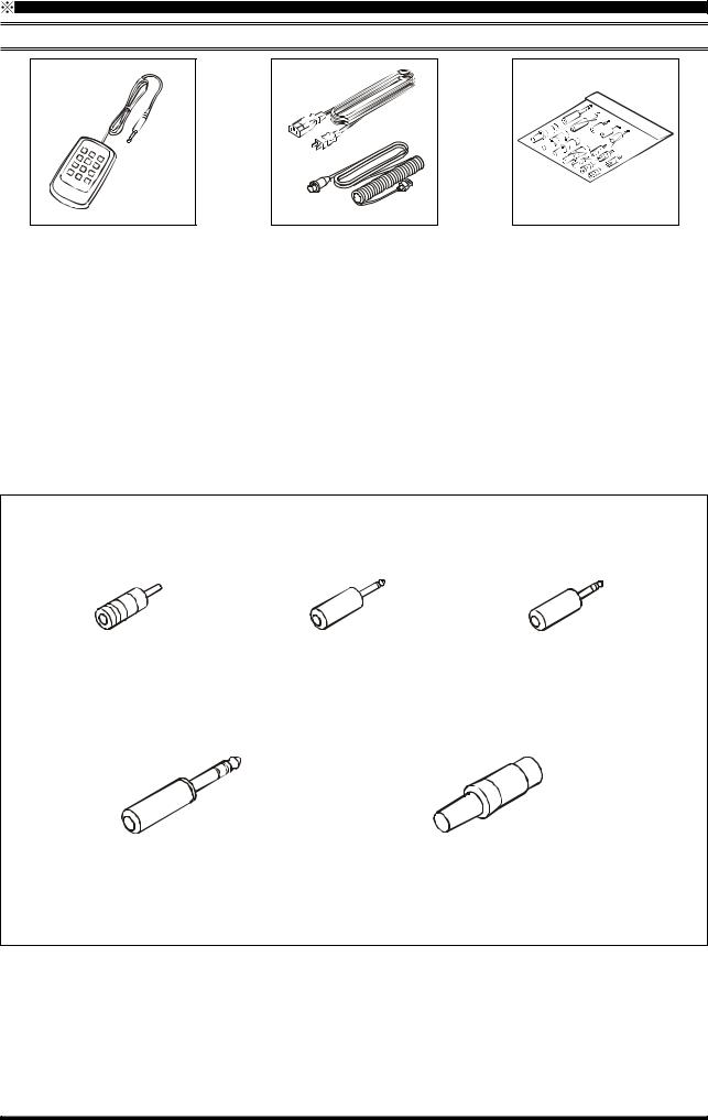
Plugs |
Operating Manual
Warranty Card
1 |
AC Power Cord |
|
|
USA: |
T9017882 |
|
Europe: |
T9013285 |
|
Australia: |
T9013283A |
|
UK: |
T9013285 |
2 |
This microphone cable is for use with the optional |
|
|
MD-200A8X, MD-100A8X, or MH-31B8 micro- |
|
|
phones. |
|
Plug Details and Part Numbers
RCA Plug (P0091365) |
3.5 mm 2-contact Plug |
3.5 mm 3-contact Plug |
6 pcs |
(P0090034) |
(P0091046) |
|
2 pcs |
1 pc |
1/4-inch 3-contact Plug |
4-pin DIN Plug (P0091004) 1 pc |
(P0090008) |
5-pin DIN Plug (P0091006) 1 pc |
2 pcs |
7-pin DIN Plug (P0091419) 1 pc |
|
8-pin DIN Plug (P0090651) 1 pc |
Items are shown for illustrative purposes only, and may vary slightly in appearance.
Page 10 |
FT DX 9000 CONTEST OPERATION MANUAL |
OPTIONS
AVAILABLE OPTIONS
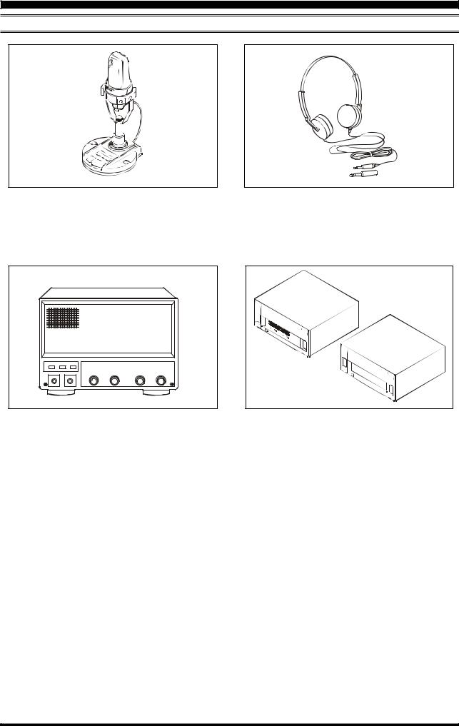
MD-200A8X
Ultra-High-Fidelity Desk-Top Microphone
MD-200A8X
Desk-Top Microphone
MD-100A8X
External Speaker with Dual Speakers and Audio Filter SP-9000
Lightweight Stereo Headphones
YH-77STA
Linear Amplifier / AC Power Supply
VL-1000 / VP-1000
Customization Options
Dual Receive Unit |
RXU-9000 |
Sub Band VRF Unit |
VRF-9000 |
RF μ-Tuning Unit A |
MTU-160 (160 m Band) |
RF μ-Tuning Unit B |
MTU-80/40 (80/40 m Bands) |
RF μ-Tuning Unit C |
MTU-30/20 (30/20 m Bands) |
Data Management Unit |
DMU-9000 |
TFT Display Unit |
TFT-9000 |
FT DX 9000 CONTEST OPERATION MANUAL |
Page 11 |

INSTALLATION AND INTERCONNECTIONS
ANTENNA CONSIDERATIONS
The FT DX 9000 Contest is designed for use with any antenna system providing a 50 Ohm resistive impedance at the desired operating frequency. While minor excursions from the 50-Ohm specification are of no consequence, the transceiver’s Automatic Antenna Tuner may not be able to reduce the impedance mismatch to an acceptable value if the Standing Wave Ratio (SWR) present at the Antenna jack is greater than 3:1.
Every effort should, therefore, be made to ensure that the impedance of the antenna system utilized with the FT DX 9000 Contest be as close as possible to the specified 50-Ohm value.
Any antenna to be used with the FT DX 9000 Contest must, ultimately, be fed with 50 Ohm coaxial cable. Therefore, when using a “balanced” antenna such as a dipole, remember that a balun or other matching/balancing device must be used so as to ensure proper antenna performance.
The same precautions apply to any additional (receive-only) antennas connected to the RX ANT jack; if your receive-only antennas do not have an impedance near 50 Ohms at the operating frequency, you may need to install an external antenna tuner to obtain optimum performance.
ABOUT COAXIAL CABLE
Use high-quality 50-Ohm coaxial cable for the lead-in to your FT DX 9000 Contest transceiver. All efforts at providing an efficient antenna system will be wasted if poor quality, lossy coaxial cable is used. This transceiver utilizes standard “M” (“PL-259”) type connectors, except for the “RX OUT” BNC connectors used for special filters, etc.
1/16" |
Adapter |
3/4" |
|
1 1/8" |
3/4'' |
|
1/8'' |
3/8'' |
5/8'' |
Typical PL-259 Installation
Page 12 |
FT DX 9000 CONTEST OPERATION MANUAL |
INSTALLATION AND INTERCONNECTIONS
GROUNDING
The FT DX 9000 Contest HF transceiver, like any other HF communications apparatus, requires an effective ground system for maximum electrical safety and best communications effectiveness. A good ground system can contribute to station efficiency in a number of ways:
It can minimize the possibility of electrical shock to the operator.
It can minimize RF currents flowing on the shield of the coaxial cable and the chassis of the transceiver; such currents may lead to radiation which can cause interference to home entertainment devices or laboratory test equipment.
It can minimize the possibility of erratic transceiver/accessory operation caused by RF feedback and/or improper current flow through logic devices.
An effective earth ground system make take several forms; for a more complete discussion, see an appropriate RF engineering text. The information below is intended only as a guideline.
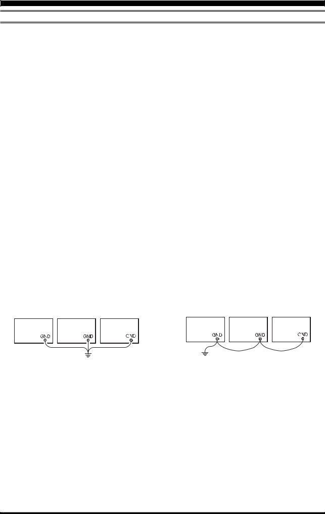
Typically, the ground connection consists of one or more copper-clad steel rods, driven into the ground. If multiple ground rods are used, they should be positioned in a “V” configuration, and bonded together at the apex of the “V” which is nearest the station location. Use a heavy, braided cable (such as the discarded shield from type RG-213 coaxial cable) and strong cable clamps to secure the braided cable(s) to the ground rods. Be sure to weatherproof the connections to ensure many years of reliable service. Use the same type of heavy, braided cable for the connections to the station ground bus (described below).
Inside the station, a common ground bus consisting of a copper pipe of at least 25 mm (1”) diameter should be used. An alternative station ground bus may consist of a wide copper plate (single-sided circuit board material is ideal) secured to the bottom of the operating desk. Grounding connections from individual devices such as transceivers, power supplies, and data communications devices (TNCs, etc.) should be made directly to the ground bus using a heavy, braided cable.
Do not make ground connections from one electrical device to another, and thence to the ground bus. This so-called “DaisyChain” grounding technique may nullify any attempt at effective radio frequency grounding. See the drawing below for examples of proper grounding techniques.
Inspect the ground system - inside the station as well as outside - on a regular basis so as to ensure maximum performance and safety.
Besides following the above guidelines carefully, note that household or industrial gas lines must never be used in an attempt to establish an electrical ground. Cold water pipes may, in some instances, help in the grounding effort, but gas lines represent a significant explosion hazard, and must never be used.
Transceiver |
Linear |
Power |
Transceiver |
Linear |
Power |
|
Amplifier |
Supply |
|
Amplifier |
Supply |
|
|
|
|
"Daisy Chain" |
|
PROPER GROUND CONNECTION |
IMPROPER GROUND CONNECTION |
||||
FT DX 9000 CONTEST OPERATION MANUAL |
Page 13 |
INSTALLATION AND INTERCONNECTIONS
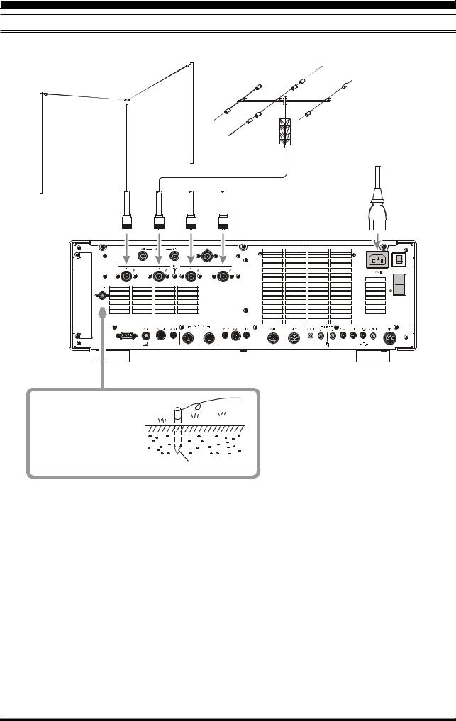
CONNECTION OF ANTENNA AND POWER CABLES
Please follow the outline in the illustration regarding the proper connection of antenna coaxial cables, as well as the AC power cable.
ANTENNA "1" |
ANTENNA "2" |
ANTENNA "3" |
ANTENNA "4" |
1 |
2 |
Use a short, thick, braided cable to connect your sta-
tion equipment to the buried ground rod (or alternative earth ground system).
Ground Rod
 Advice
Do not position this apparatus in a location with direct exposure to sunshine.
Do not position this apparatus in a location exposed to dust and/or high humidity.
Ensure adequate ventilation around this apparatus, so as to prevent heat build-up and possible reduction of performance due to high heat.
Do not install this apparatus in a mechanically-unstable location, or where objects may fall onto this product from above.
To minimize the possibility of interference to home entertainment devices, take all precautionary steps including separation of TV/FM antennas from Amateur transmitting antennas to the greatest extent possible, and keep transmitting coaxial cables separated from cables connected to home entertainment devices.
Ensure that the AC power cord is not subject to undue stress or bending, which could damage the cable or cause it to be accidentally unplugged from the rear panel AC input jack.
Be absolutely certain to install your transmitting antenna(s) such that they cannot possibly come in contact with TV/FM radio or other antennas, nor with outside power or telephone lines.
Page 14 |
FT DX 9000 CONTEST OPERATION MANUAL |
INSTALLATION AND INTERCONNECTIONS
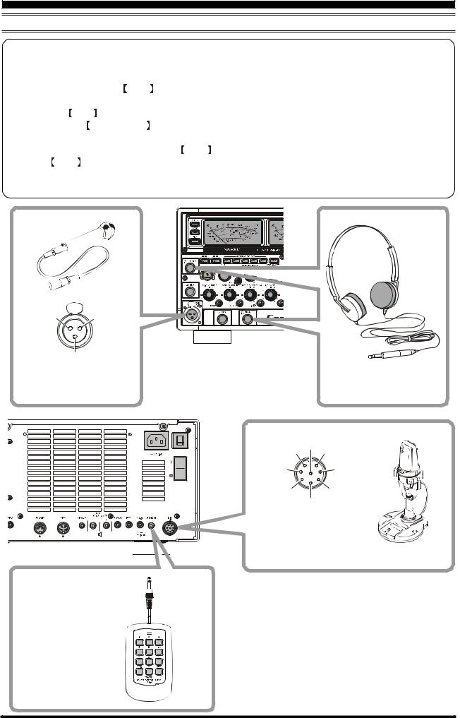
CONNECTION OF MICROPHONE, HEADPHONES AND FH-2 REMOTE CONTROL KEYPAD
This transceiver was shipped from the factory in configuration for a microphone input via the Front Panel XLR connector. To use the Rear Panel microphone with an 8-pin round connector, please change the microphone set up via the Menu.
1. |
To do this, first press the MNU key. |
2. |
The Menu list will appear on the LCD display screen. |
3. |
Rotate the Main tuning dial to select menu item “MODE-SSB 069 SSB MIC SELECT.” |
4. |
Now rotate the CLAR/VFO-B knob to change the setting to Rear. |
|
The available selections are FRONT-REAR-DATA-PC. |
5. |
To save the set-up, press and hold in the MNU key for 2 seconds. |
|
If the MNU key is not held for 2 seconds, the set-up will not be saved. |
 Note
Note : To use the AM or FM mode, please select Menu items 040 for AM and 059 for FM, and follow the same procedure above.
MIC-Hot |
MIC-GND |
|
|
MIC-Cold |
|
XLR connector Type Microphone |
1/4-inch 3-contact jack |
|
|
|
Stereo Headphones |
|
MIC |
UP |
MIC GND |
+5V |
PTT |
DOWN |
GND |
|
|
|
FAST |
8-pin Connector Type Microphone
LOCK
ON


 OFF
OFF
FH-2 Remote Control
Keypad
FT DX 9000 CONTEST OPERATION MANUAL |
Page 15 |

INSTALLATION AND INTERCONNECTIONS
KEY, KEYER, AND COMPUTER-DRIVEN KEYING INTERCONNECTIONS
The FT DX 9000 Contest includes a host of features for the CW operator, the functions of which will be detailed in the “Operation” section later. Besides the built-in Electronic Keyer, two key jacks are provided, one each on the front and rear panels, for convenient connection to keying devices.
The Menu system allows you to configure the front and rear panel KEY jacks according to the device you wish to connect. For example, you may connect your keyer paddle to the front panel KEY jack, and use Menu #42 for paddle input, while connecting the rear panel’s KEY jack to the keying line from your personal computer (which emulates a “straight key” for connection purposes), and configure the rear panel jack using Menu #44.
Both KEY jacks on the FT DX 9000 Contest utilize “Positive” keying voltage. Key-up voltage is approximately +5V DC, and key-down current is approximately 1 mA.
2
DOT DASH COMMON
DOT DASH
COMMON
 Advice
When connecting a key or other device to the KEY jacks, use only a 3-pin (“stereo”) 1/4” phone plug; a 2-pin plug will place a short between the ring and (grounded) shaft of the plug, resulting in a constant “key-down” condition in some circumstances.
Page 16 |
FT DX 9000 CONTEST OPERATION MANUAL |
INSTALLATION AND INTERCONNECTIONS
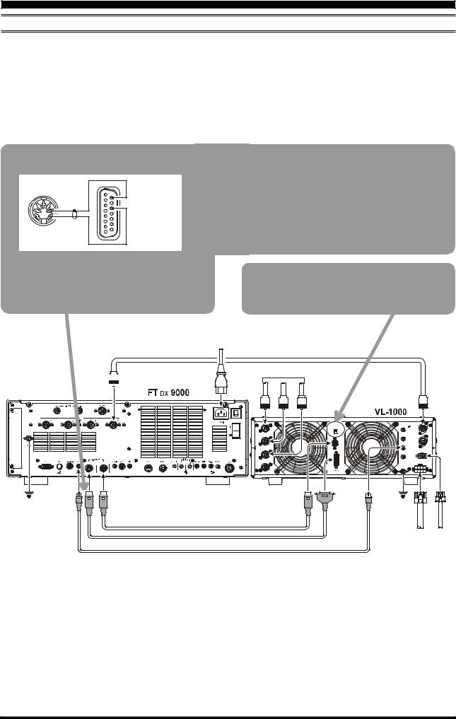
VL-1000 LINEAR AMPLIFIER INTERCONNECTIONS
Be sure that both the FT DX 9000 Contest and VL-1000 are turned off, then follow the installation recommendations contained in the illustration.
On the rear panel of the VL-1000, please set the “ATT” switch to the “ON” position. The 200-Watt power output from the FT DX 9000 Contest is far in excess of what is required to drive the VL-1000 to its full rated output.
 Note
Note
Please refer to the VL-1000 Operating Manual for details regarding amplifier operation. Please do not attempt to connect or disconnect coaxial cables when your hands are wet.
Control Cable Modification
Pin 9
F SET COMMON
Pin 3
GND
Pin 11
F SET 2
Pin 7
TRQ
Please cut off the RCA connector on one end of the CONTROL Cable supplied with the VL-1000, and install a 7-pin DIN connector in its place, according to the illustration.
About the CONTROL Cable
The VL-1000 may be operated with the FT DX 9000 Contest whether or not the CONTROL Cable is connected; however, the CONTROL Cable allows you to tune up the amplifier automatically by just pressing the  F SET
F SET or
or  TUNE
TUNE key on the VL-1000, so as to transmit a carrier for tuning purposes.
To link the FT DX 9000 Contest and VL-1000 Power switches, set the VL-1000 REMOTE switch to the ON position.
 ANT
ANT
|
2 |
|
1 |
GND |
EXT ALC |
BAND DATA 2 |
BAND DATA 1 |
ANTENNA CABLE Supplied w/VL-1000
~AC IN |
ANTENNA |
|
|
|
ANT 1 |
ANT 2 |
ANT 3 |
INPUT 1 |
|
ANT 1
ANT 2
ANT 3
ANT 4
BAND DATA CABLE Supplied w/VL-1000
REMOTE |
INPUT 1 |
PTT 1 |
|
ON |
|
OFF |
PTT 2 |
BAND DATA 1 |
|
|
INPUT 2 |
|
ALC 1 |
CONTROL
ALC 2
|
|
|
|
DC48V IN |
|
|
|
|
GND |
|
|
|
BAND DATA 2 |
|
|
|
|
BAND-DATA 1 |
BAND-DATA 2 |
ALC 1 |
GND |
DC 48V IN |
CONTROL |
CONTROL CABLE User constructed |
1000 |
1000 |
||
VP- |
VP- |
|||
|
|
|||
|
|
¾ |
¾ |
|
ALC CABLE |
Supplied w/VL-1000 |
|
|
|
FT DX 9000 CONTEST OPERATION MANUAL |
Page 17 |

INSTALLATION AND INTERCONNECTIONS
INTERFACING TO OTHER LINEAR AMPLIFIERS
|
|
50 MHz Antenna |
ANTENNA CABLE 50Ω |
ANT 1 |
ANT 2 |
|
|
|
~AC IN |
GND |
EXT ALC |
TX GND |
HF Antenna |
|
1 |
|
|
|
ANT 1 |
|
INPUT |
|
|
|
RF OUT |
RF IN |
GND |
FUSE |
AC |
GND ALC GND RELAY |
|
|
||||
|
|
|
GND |
|
|
 Note
Note
The TX/RX switching in the linear amplifier is controlled by switching components in the transceiver. The relay circuit of the FT DX 9000 Contest used for this switching is capable of switching AC voltage of 100 Volts at up to 300 mA, or DC voltages or 60 V at 200 mA or 30 V at up to 1 Amp. In order to engage the switching relay, use Menu item “TX GNRL 156 EXT AMP TX-GND” within the “TX GNRL” Menu Group; set this Menu selection to “ENABLE” to activate the amplifier switching relay.
The specified range for ALC voltage to be used with the FT DX 9000 Contest is 0 to –4 Volts DC.
Amplifier systems utilizing different voltages will not work correctly with the FT DX 9000 Contest, and their ALC lines must not be connected if this is the case.
Page 18 |
FT DX 9000 CONTEST OPERATION MANUAL |
PLUG/CONNECTOR PINOUT DIAGRAMS
CAT |
BAND DATA1 |
BAND DATA2 |
|
N/A |
EXT ALC |
+13V |
|
SERIAL OUT |
TX GND |
||
SERIAL IN |
TX GND |
||
GND |
|||
N/A |
GND |
||
BAND DATA A |
|||
GND |
NC |
||
BAND DATA B |
|||
N/A |
NC |
||
BAND DATA C |
|||
N/A |
TXINH |
||
BAND DATA D |
|||
N/A |
FSET |
||
LINEAR |
|||
NC |
|
||
(as viewed from rear panel) |
(as viewed from rear panel) |
(as viewed from rear panel) |
|
PACKET |
ROTATOR |
RTTY |
|
DATA IN |
RT1 |
RX OUT |
|
RT2 |
|||
GND |
|||
RT3 |
PTT |
||
PTT |
|||
RT4 |
GND |
||
DATA OUT |
|||
GND |
SHIFT |
||
BUSY |
|||
NC |
|
||
|
|
||
(as viewed from rear panel) |
(as viewed from rear panel) |
(as viewed from rear panel) |
|
MIC (XLR) |
MIC |
RCA PLUG |
|
|
UP |
|
|
|
+5V |
||
|
DOWN |
GND or |
|
MIC-GND |
|
||
FAST |
|
||
MIC-Hot |
|
||
GND |
|
||
MIC-Cold |
|
||
PTT |
|
||
|
|
||
|
MIC GND |
SIGNAL or |
|
|
MIC |
||
(as viewed from front panel) |
(as viewed from rear panel) |
|
|
REMOTE |
AF OUT |
EXT SPKR |
|
GND |
SUB(VFO-B) |
GND |
|
|
|
|
SIGNAL |
MAIN(VFO-A) GND |
SIGNAL |
|
|
|
|
|
|
|
|
|
PHONE |
KEY |
||||
|
|
|
For Internal Keyer |
For Straight Key |
||
|
|
|
|
|
|
|
|
|
|
|
|
|
|
|
|
|
|
|
|
|
MAIN SUB GND |
DOT DASH COMMON |
KEY |
GND |
|
|
|
Do not use |
|
|
|
2-conductor type plug |
FT DX 9000 CONTEST OPERATION MANUAL |
Page 19 |
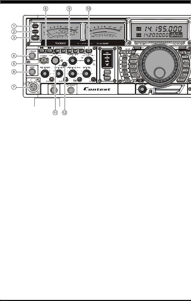
FRONT PANEL CONTROLS
 MOX Switch
Pressing this button engages the PTT (Push to Talk) circuit, to activate the transmitter. It must be in the undepressed position for reception. This switch replicates the action of the Push to Talk (PTT) switch on the microphone. When engaging the  MOX
MOX switch, or otherwise causing a transmission to be started, be certain you have either an antenna or 50-Ohm dummy load connected to the selected Antenna jack.
 VOX Switch
VOX Operation: This button enables automatic voiceactuated transmitter switching in the SSB, AM, and FM modes. While activated, the LED inside this button glows red. The controls affecting VOX operation are the front panel’s  VOX
VOX and
and  DELAY
DELAY knobs (see section (
 ) below. By proper adjustment of these controls, hands-free voice-actuated operation is possible.
 DIM Switch
Press this button to lower the illumination intensity of the analog meters, the frequency display, and the LCD. Press it once more to restore full brightness.
 Advice
Menu Items “DISPLAY 014 DIMMER-METER” and “DISPLAY 015 DIMMER-VFD” allow you to configure the dimming levels for the analog meters and the frequency display/LCD independently, so you can customize the brightness levels.
 PHONES Jack
A 1/4-inch, 3-contact jack accepts either monaural or stereo headphones with 2- or 3-contact plugs. When a plug is inserted, the loudspeaker is disabled. With stereo headphones such as the optional YH-77STA, you can monitor both VFO-A and VFO-B receiver channels at the same time during Dual Receive operation. Note: When wearing headphones, we recommend that you turn the AF Gain levels down to their lowest settings before turning power on, to minimize the impact on your hearing caused by audio “pops” during switchon.
 POWER Switch
Press and hold in this switch for two seconds to turn the transceiver on, after first setting the rear panel Power switch to the “I” position. Press and hold in this switch for two seconds, similarly, to turn the transceiver off. If the rear panel’s Power switch is set to the “O” position, the front panel  POWER
POWER switch will not function.
 Advice
This is the actual power On/Off switch for turning on the transceiver. When the rear panel’s Power switch is set to the ( I ) position, power is supplied to the OCXO to stabilize the reference oscillator, and the remainder of the transceiver is set in a “stand-by” mode, awaiting the command for the transceiver to switch on via the front panel  POWER
POWER switch. For further information on the rear panel Power switch, please see the discussion on page 34.
Page 20 |
FT DX 9000 CONTEST OPERATION MANUAL |

FRONT PANEL CONTROLS
 KEY Jack
This 1/4-inch, 3-contact jack accepts a CW key or keyer paddles (for the built-in electronic keyer), or output from an external electronic keyer. Pinout is shown on page 16. Key up voltage is 5 V, and key down current is 1 mA. This jack may be configured for keyer, “Bug,” “straight key,” or computer keying interface operation via Menu Selection “MODE-CW 041 F-KEYER TYPE” (see page 120). There is another jack with the same name on the rear panel, and it may be configured independently for Internal Keyer or pseudo-straight-key operation.
 Note
Note
You cannot use a 2-contact plug in this jack (to do so produces a constant “key down” condition).
 Cannon (“XLR”) Microphone Connector
This Cannon-type (XLR) connector accepts input from the Microphone or other XLR-equipped microphone system. MIC connector pinout is shown on page 15. Proper microphone input impedance is 500 ~ 600 Ohms.
If you are using a condenser microphone requiring 48 Volts DC, you may enable this voltage to appear on the microphone line; see page 67. When the 48-volt supply line has been enabled, the LED adjacent to the MIC jack will glow red.
To disconnect the microphone plug, draw out the microphone plug while pressing and holding in the silver push-button.
 IPO (Intercept Point Optimization) Switch
The  IPO(A)
 Lamp-button may be used to set the optimum receiver front end characteristics of the VFO- A circuit for a very strong-signal environment. Selecting IPO bypasses the front end RF amplifier and feeds the received signals directly to the first mixer of the VFO-A receiver circuit. While the IPO feature is activated, this button will remain illuminated.
The  IPO(B)
 Lamp-button, similarly, allows direct feed of the received signals to the first mixer of the VFO-B circuit. While the IPO feature is activated on the VFO-B, this button will be lit.
 Advice
The FT DX 9000 Contest’s first mixer is an active type, using four SST310 Junction FETs. This mixer design provides gain to the receiver chain, so the noise figure of the receiver is fundamentally lower than with some other designs. Therefore, it frequently is not necessary to utilize the RF preamplifier, and the receiver Intercept Point will be substantially increased by engaging IPO, so as to feed the incoming signals directly to the first (active) mixer. We recommend that IPO be switched on whenever possible.
 ANTENNA SELECT Switches
These momentary buttons select the antenna jack on the rear panel, with the selection indicated by the LED in each button. When an antenna has been selected for operation on the VFO-A, the LED in the button glows red. When an antenna has been selected for operation on the VFO-B, the LED in the button glows umber.
 TUNE Switch
This is the on/off switch for the FT DX 9000 Contest’s Automatic Antenna Tuner.
Pressing this button momentarily places the antenna tuner in line between the transmitter final amplifier and the antenna jack (the LED will become illuminated). Reception is not affected.
Pressing and holding in this button for 1/2 second, while receiving in an amateur band, activates the transmitter for a few seconds while the automatic antenna tuner rematches the antenna system impedance for minimum SWR. The resulting setting is automatically stored in one of the antenna tuner’s 100 memories, for instant automatic recall later when the receiver is tuned near the same frequency.
Pressing this button momentarily, while the Tuner is engaged, will take the Automatic Antenna tuner out of the transmit line.
 Note
Note
When the Automatic Antenna tuner is tuning itself, a signal is being transmitted. Therefore, be absolutely certain that an antenna or dummy load is connected to the selected antenna jack before pressing and holding in the  TUNE
TUNE button to start antenna tuning.
 METER Switch
This control switch determines the function of the Main Meter during transmission.
COMP: Indicates the RF speech compressor level (SSB modes only).
PO: Indicates the power output level.
SWR: Indicates the Standing Wave Ratio (Forward: Reflected).
IDD: Indicates the final amplifier drain current. MIC LVL: Indicates the relative microphone level.
 MONI (Monitor) Switch
This button enables the transmit (RF) monitor in all modes (except CW, in which the monitor function is always on, to produce the sidetone). While activated, the LED in this button glows red. Adjustment of the Monitor level is accomplished using the  MONI
MONI knob, located just to the right of the
  MONI
MONI switch.
 Advice
When using headphones, the Monitor is highly useful for making adjustments to the Parametric Equalizer or other voice quality adjustments, because the voice quality heard in the headphones is such a “natural” reproduction of the transmitted audio quality.
FT DX 9000 CONTEST OPERATION MANUAL |
Page 21 |
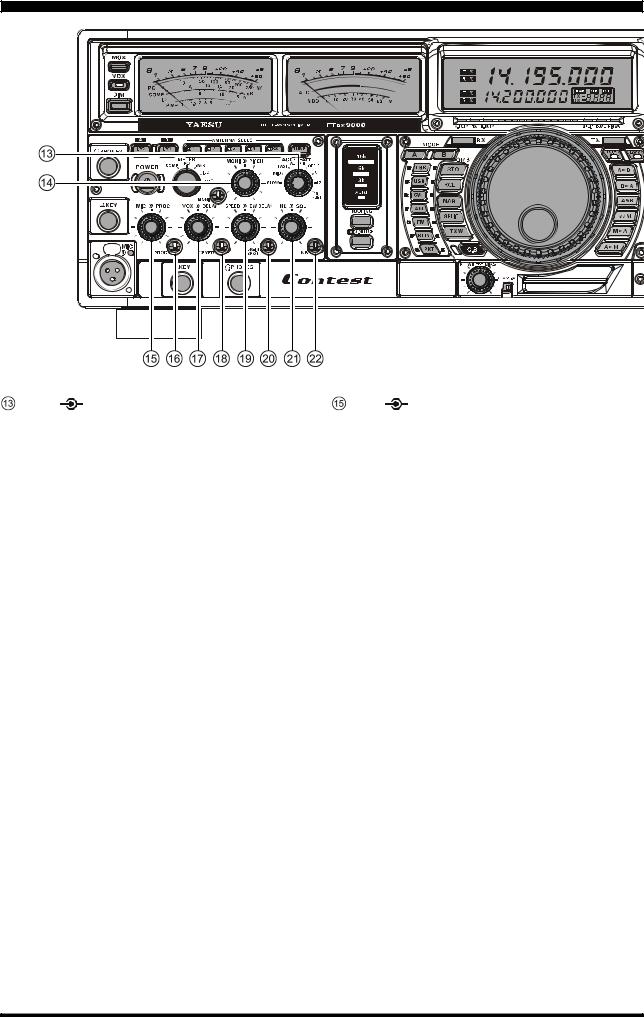
FRONT PANEL CONTROLS
AGC |
ATT Knobs |
MIC |
PROC Knobs |
AGC Knobs
This switch selects the AGC characteristics for the VFO-A.
ATT Knobs
This switch selects the degree of attenuation, if any, to be applied to the VFO-A.
 Advice
The Attenuator may be used in conjunction with the IPO switch (# , described previously) to provide two stages of signal reduction when an extremely strong signal is being received.
 MONI
MONI PITCH Knobs
MONI Knob
The inner  MONI
MONI knob adjusts the audio level of the transmit RF monitor during transmission (relative to the
  AF GAIN
 control: #
  , described later), when activated by the
  MONI
MONI button (#
 , described previously).
PITCH Knob
The outer PITCH
PITCH knob selects your preferred CW tone pitch (from 300 ~ 1000 Hz, in 50 Hz increments). The Tx sidetone, receiver IF passband, and display offset from the BFO (carrier) frequency are all affected simultaneously. The Pitch control setting also affects the operation of the CW Tuning Indicator, as the center frequency of the CW Tuning Indicator will follow the setting of this control.
MIC Knob
The inner  MIC
MIC knob adjusts the microphone input level for (non-processed) SSB transmission.
 Advice
If you adjust the MIC Gain while speaking in a louder- than-normal voice level and watching the ALC level on the right-side meter, adjust the MIC Gain so that the ALC reaches over to the right edge of the ALC scale. Then, when you speak in a more normal voice level, you’ll be certain not to be over-driving the mic amplifier stage.
PROC Knob
The outer  PROC
PROC knob sets the compression (input) level of the transmitter RF speech processor in the SSB and modes, when activated by the button with the same name (see next section).
 PROC (Processor) Switch
This button enables the RF speech processor for SSB transmission. Processing level is set by the outer control with the same name (see previous section). While activated, the LED in this button glows red.
 Advice
The Speech Processor is a tool for increasing the average power output through a compression technique. However, if the PROC level control is advanced too far, the increase in compression becomes counter-pro- ductive, as intelligibility will suffer. We recommend that you monitor the sound of your signal using the Monitor (with headphones), then advance the PROC level only as far as required to obtain a useful increase in average power output.
When the optional Data Management Unit (DMU-9000) and TFT Display Unit (TFT-9000) are installed, you
Page 22 |
FT DX 9000 CONTEST OPERATION MANUAL |

FRONT PANEL CONTROLS
may use the Audio Scope/Oscilloscope page on the TFT to help you adjust the setting of the Compression Level of the Speech Processor for the optimum performance using your voice and microphone.
 VOX
VOX DELAY Knobs
VOX Knob
The inner  VOX
VOX knob sets the gain of the VOX circuit, to set the level of microphone audio needed to activate the transmitter during voice operation while the
  VOX
VOX switch (#
 , described previously) is engaged. The
  VOX
VOX switch must be switched On to engage the VOX circuit.
DELAY Knob
The outer  DELAY
DELAY knob sets the hang time of the VOX circuit, between the moment you stop speaking, and the automatic switch from transmit back to receive. Adjust this for smooth VOX operation, so the receiver is only activated when your transmission is ended and you wish to receive.
For CW operation, you can adjust the keying delay separately; see control # below.
 KEYER Switch
This button toggles the internal CW keyer on and off. While activated, the LED in this button glows red. The Keyer sending speed, and the CW Hang Time are adjusted via the controls described in the next section.
 SPEED
SPEED CW DELAY Knobs
The internal Electronic Keyer is activated by the  KEYER
KEYER switch, described in the previous section.
SPEED Knob
The inner SPEED
SPEED knob adjusts the keying speed of the internal CW keyer. Clockwise rotation increases the sending speed.
CW DELAY Knob
This outer  CW DELAY
 knob sets the hang time of the CW “VOX” circuit, between the moment you stop sending, and the automatic switch from transmit back to receive during “Semi-break-in” operation. Adjust this just long enough to prevent the receiver from being restored during word spaces at your preferred sending speed. Clockwise rotation increases the hang time.
 Note
Note
The SSB VOX hang time is adjusted via the DELAY control (#
 , described previously).
 BK-IN/SPOT Switches
This button turns the full break-in (QSK) CW capability on and off. While QSK is activated, the LED in this button glows red.
The  SPOT
SPOT button turns on the CW receiver spotting tone; by matching the SPOT tone to that of the incoming CW signal (precisely the same pitch), you will be “zero beating” your transmitted signal on to the frequency of the other station.
 NB/SQL Knobs
NB Knob
The inner  NB
NB knob adjusts the noise blanking level when the (analog) IF noise blanker is activated by pressing the
  NB
NB switch (#
 below). The Noise Blanker is activated via the
  NB
NB switch, described in the next section.
SQL Knob
The outer  SQL
SQL knob sets the signal level threshold at which VFO-A audio is muted, in all modes. It is very useful during local rag-chews, to eliminate noise between incoming transmissions. This control is normally kept fully counter-clockwise (off), except when scanning and during FM operation.
 NB Switch
Pressing this button activates the (analog) IF Noise Blanker, which may help reduce many different types of man-made impulse noise (but not atmospherics). When the Noise Blanker is activated, the LED inside the button will glow red. Adjustment of the Noise Blanker level is accomplished via the NB
NB knob (#
 above), described in the previous section.
FT DX 9000 CONTEST OPERATION MANUAL |
Page 23 |

FRONT PANEL CONTROLS
 KEY Jack
This 1/4-inch, 3-contact jack accepts a CW key or keyer paddles (for the built-in electronic keyer), or output from an external electronic keyer. Pinout is shown on page 16. Key up voltage is 5 V, and key down current is 1 mA. This jack may be configured for keyer, “Bug,” “straight key,” or computer keying interface operation via Menu item “MODE-CW 041 F-KEYER TYPE” (see page 120). There is another jack with the same name on the rear panel, and it may be configured independently for Internal Keyer or pseudo-straight-key operation.
 Note
Note
This Key jack is connected in parallel with the jack with the same name on the front panel.
You cannot use a 2-contact plug in this jack (to do so produces a constant “key down” condition).
 PHONES Jack
A 1/4-inch, 3-contact jack accepts either monaural or stereo headphones with 2- or 3-contact plugs. When a plug is inserted, the loudspeaker is disabled. With stereo headphones such as the optional YH-77STA, you can monitor both VFO-A and VFO-B channels at the same time during Dual Receive operation.
 Note
Note
This Phones jack is connected in parallel with the jack with the same name on the front panel.
When wearing headphones, we recommend that you turn the AF Gain levels down to their lowest settings before turning power on, to minimize the impact on your hearing caused by audio “pops” during switch-on.
 ROOFING Switch
This button selects the bandwidth for the VFO-A receiver’s first IF Roofing Filter. Available selections are 3 kHz, 6 kHz, 15 kHz, or Auto, and the LED indicator will change according to the bandwidth selected.
 Advice
Because the roofing filter is in the first IF, the protection it provides against interference is quite significant. When set to AUTO, the SSB bandwidth is 6 kHz, while CW is 3 kHz and FM/RTTY are 15 kHz. On a crowded SSB band, however, you may wish to select the 3 kHz filter, for the maximum possible interference rejection.
 D.NOTCH Switch
This button turns the VFO-A Digital Notch Filter on and off. When the Digital Notch Filter is activated, the LED indicator will glow red. This is an automatic circuit, and there is no adjustment knob for the D.NOTCH.
 MODE Switches
A, B Button
Pressing the  A
A or
or  B
B switch will illuminate the respective indicator imbedded within the switch, allowing adjustment of the operating mode on the VFO- A or VFO-B. Pressing the
  A
A switch causes the indicator to glow Red, signifying VFO-A is being adjusted. Similarly, pressing the
  B
B switch will cause its indicator to glow Orange, signifying VFO-B adjustment.
 Advice
When changing bands, be sure to press the A or  B
B switch first, then press the appropriate Band selector switch, so as to change operating frequencies on the proper (VFO-A or VFO-B).
Page 24 |
FT DX 9000 CONTEST OPERATION MANUAL |

FRONT PANEL CONTROLS
LSB, USB, CW, AM, FM, RTTY, PKT Button
Pressing the  LSB
LSB ,
,  USB
USB ,
,  CW
CW ,
,  AM
AM ,
,  FM
FM ,
,  RTTY
RTTY , or
, or  PKT
PKT button will select the operating mode. Pressing the
  CW
CW ,
,  AM
AM ,
,  RTTY
RTTY , or
, or  PKT
PKT button multiple times will switch between the alternate operating features that can be used on these modes (covered later). Also, when you press and hold in the
  PKT
PKT button for one second, the user-pro- grammed custom function setting mode will be activated.
 QMB (Quick Memory Bank) Switch
STO (Store) Button
Pressing this button copies operating information (frequency, mode, bandwidth, and also repeater direction/ shift frequency and CTCSS functions on the FM mode) into consecutive QMB Memories.
RCL (Recall) Button
Pressing this button recalls one of up to five Quick Memory Bank memories for operation.
 NAR (Narrow) Switch
In the SSB/CW mode, this button is used to set the bandwidth of the DSP IF filters to a user-programmed bandwidth (default values are SSB: 1.8 kHz, CW/ RTTY/PSK: 300 Hz, AM: 6 kHz). When  NAR
NAR has been engaged, the
  WIDTH
WIDTH knob will be disabled. In the AM mode, this button is used to toggle the receiver’s bandwidth between wide (9 kHz) and narrow (6 kHz).
In the FM mode on the 28 MHz and 50 MHz bands, this button is used to toggle the FM deviation/bandwidth between wide (± 5.0 kHz Dev./25.0 kHz BW) and narrow (± 2.5 kHz Dev./12.5 kHz BW).
Pressing the  A
A or
or  B
B button (located above the MODE selection buttons) will select either the VFO- A or VFO-B for individual bandwidth setting.
 Advice
When  NAR
NAR has been engaged, the
  WIDTH
WIDTH knob will be disabled, although IF Shift still works normally.
 SPLIT Switch
Pressing this button to activates split frequency operation between the VFO-A, used for transmission and VFO-B, used for reception. The same name LED located at the right of the main tuning knob glows orange while this function is active.
If you press and hold in the  SPLIT
SPLIT switch for two seconds, the “Quick Split” feature will be engaged, whereby the VFO-B will automatically be set to a frequency 5 kHz higher than the VFO-A frequency, and the transceiver will be placed in the Split mode.
 TXW “TX Watch” Switch
Pressing this key lets you monitor the transmit frequency when split frequency operation is engaged. When receiving on the transmit frequency, the LED indicator will glow green. Press this key again to return to normal operation.
 RX Indicator/Switch
This switch, when pressed, engages the VFO-A ; the indicator will glow Green when the VFO-A is active. When the VFO-A is active, pressing this button momentarily will mute the receiver, and the indicator will blink. Pressing the button once more will restore receiver operation, and the indicator will glow Green steadily.
 TX Indicator/Switch
When this button is pushed, the indicator will glow Red, and the transmitter will be engaged on the same frequency and mode as was set up for the VFO-A (subject to any Clarifier offset, of course).
 Advice
If this indicator is not illuminated, it means that the VFO-B TX indicator has been selected (it will be glowing Red). In this case, transmission will be effected on the frequency and mode programmed for the VFO- B.
 Main Dial Knob
This large knob adjusts the operating frequency of the VFO-A or a recalled memory. Clockwise rotation of this knob increases the frequency. Default tuning increments are 10 Hz (100 Hz in AM and FM modes); when the  FAST
FAST switch is pressed, the tuning steps increase. The available steps are:
Operating Mode |
1 Step* |
1 Dial Rotation |
LSB/USB/CW/RTTY/PKT(LSB) |
10 Hz (100 Hz) |
10 kHz (100 kHz) |
AM/FM/PKT(FM) |
100 Hz (1 kHz) |
100 kHz (1 MHz) |
*Numbers in parentheses indicate steps when the [FAST] switch is On.
 Advice
The tuning steps for the  Main
Main Tuning Dial (described in this section) are set, at the factory, to 10 Hz per step. Via Menu item “TUNING 129 MAIN DIAL STEP,” however, you may change this setting from 10 Hz to 1 Hz instead. When 1 Hz basic steps are selected, the action of the
  FAST
FAST button (#
 below) will be changed to 1/10 of the values listed above.
 FAST Switch
Pressing this button will increase or decrease the tuning rate of the  Main
Main Tuning Knob (#
 above) by a factor of ten, as mentioned in the previous section. When this function is activated, the LED inside the button will glow red.
 LOCK Switch
This button toggles locking of the main tuning knob, to prevent accidental frequency changes. When the button is active, the  Main
Main Tuning Knob (#
 , described previously) can still be turned, but the frequency will not change, and the LED inside the button will glow red.
FT DX 9000 CONTEST OPERATION MANUAL |
Page 25 |

FRONT PANEL CONTROLS
 C.S Switch
Press this button momentarily to recall a favorite Menu Selection directly.
To program a Menu selection as the short-cut, press the  MNU
MNU key (#
 , described later) to enter the Menu, then select the item you want to set as the shortcut. Now press and hold in the
  C/S
C/S key for two seconds; this will lock in the selected Menu item as the short-cut.
 RF PWR
  BIAS Knobs
RF PWR Knob
This is the main RF Power output control for the transceiver, active in all operating modes. Clockwise rotation increases the power output. Adjust this control for the desired power output from the FT DX 9000 Contest, or for the desired system output when using a linear amplifier or transverter.
BIAS Knob
During SSB operation, pressing the CLASS-A
 but- ton (#
 below) will lower the power output to a maximum of 75 Watts, and the
  BIAS
BIAS control will then provide adjustment of the final amplifier Bias level between classes AB and A. Full Class-A operation provides an ultra-clean SSB wave-form. Because Class A is a high-bias, low-efficiency mode, you should monitor the heat sink temperature (using the “SWR” page on the LCD periodically to ensure that the operating temperature is within the safe range, and you may adjust the Bias level more toward the “AB” side if the heat sink gets too warm. The power output will not change if you adjust the setting of the
  BIAS
BIAS control.
 CLASS-A Switch
Pressing this switch engages the Class-A capability for the transmitter. The power output will be reduced to a maximum of 75 Watts, and the Bias level may be adjusted using the  BIAS
BIAS control (#
 above), described in the previous section. When Class-A operation is engaged, the Red LED inside this switch will light up. Press this switch once more to return to Class AB operation at a maximum power output of 200 Watts; the Red LED will shut off to confirm Class AB operation.
 AXB Switch
Press this button momentarily to transfer data from the VFO-A frequency (or a recalled memory channel) to the VFO-B, overwriting any previous contents in the VFO-B. Use this key to set both VFO-A and VFO-B to the same frequency and mode.
 BXA Switch
Press this button momentarily to transfer data from the VFO-B frequency to the VFO-A, overwriting any previous contents in the VFO-A. Use this key to set both VFO-A and VFO-B to the same frequency and mode.
AX B Switch
W
Pressing this button momentarily exchanges the contents of the VFO-A (or a recalled memory channel) and the VFO-B.
 V/M Switch
This button toggles VFO-A operation between the memory system and the VFO. Either “VFO,” “MEM,” or “M TUNE” will be displayed to the left of the main frequency display field to indicate the current selec-
Page 26 |
FT DX 9000 CONTEST OPERATION MANUAL |

FRONT PANEL CONTROLS
tion. If you have tuned off of a Memory channel frequency (M TUNE), pressing this button returns the display to the original memory contents (MEM), and pressing it once more returns operation to the VFO- A.
 MXA Switch
Pressing this button momentarily displays the contents of the currently-selected memory channel for three seconds.
Holding this button in for 2 seconds copies the data from the currently-selected memory to the VFO-A, as two beeps sound. Previous data in the VFO-A will be overwritten.
 AXM Switch
Pressing and holding in this key for 1/2 second (until the double beep) copies the current operating data from the VFO-A into the currently selected memory channel, overwriting any previous data stored there.
Also, pressing and holding in this button after recalling a memory, without first retuning, causes the memory channel to be “masked,” and repeating the process restores the masked memory.
 A-BUSY Indicator
This LED glows green whenever the VFO-A squelch is open. If this indicator is not illuminated, and reception seems to have been “lost” on the VFO-A for no apparent reason, check the position of the SQL
SQL control (#
 , described previously) and rotate it fully counter-clockwise to restore reception.
 TX Indicator
This indicator glows Red during transmission.
If you attempt to transmit while operating outside of an Amateur band, this indicator will blink Red, indicating an “out of band” condition.
 B-BUSY Indicator
This LED glows green whenever the VFO-B squelch is open. If this indicator is not illuminated, and reception seems to have been “lost” on the VFO-B for no apparent reason, check the position of the SQL
SQL control (#
 , described previously) and rotate it fully counter-clockwise to restore reception.
 Tuning Offset Indicator
This is a tuning scale that, as configured from the factory, provides a visual CW tuning indication of the incoming signal’s offset from your transceiver’s CW carrier frequency, as programmed by the position of the  PITCH
PITCH control (#
 , described previously).
Advice
Using Menu item “DISPLAY 016 BAR DISPLAY SELECT,” you can choose indication of the CW - TUNE, Clarifier, VRF, or IF Notch function.
 SPLIT Indicator
This indicator glows Red when the “Split” mode is engaged (with the VFO-A and VFO-B operating on different frequencies).
 DUAL Indicator
In the standard FT DX 9000 Contest version, this indicator does not function.
When the optional Dual Receive Unit (RXU-9000) is installed, the Dual Indicator will be available for use.
 HI SWR Indicator
This indicator glows Red if the directional coupler and microprocessor detect an abnormally high SWR condition (over 3.0:1) that cannot be resolved by the Automatic Antenna Tuner.
 Note
Note
If this indicator lights up, check to be sure that you have the correct antenna selected on the current operating band. If so, you will need to check the condition of the antenna, its coaxial cable, and/or the connectors on the cable so as to locate and correct the fault.
 S-Meter (VFO-A)
There are five functions on the main multi-meter. The bottom five selections in the list below are transmit functions, determined by the position of the METER switch (# , described previously):
S:Indicates the received signal strength on
the VFO-A, from S-0 to S9 +60 dB. PO: Indicates the RF Power Output, from 0 to
250 Watts on transmit.
COMP: Indicates the compression level of the speech processor, from 0 to 20 dB.
IC: Indicates the final amplifier drain current (ID), from 0 to 15 A.
SWR: Indicates the antenna system observed standing wave ratio (SWR), from 1.0 to 5.0.
MIC LVL: Indicates the relative level of modulation from the microphone amplifier stage (affected by the setting of the  MIC
MIC Gain control: #
 , described previously).
 S-Meter (VFO-B)
On receive, this meter displays signal strength of incoming signals as received on the VFO-B.
On transmit, this meter serves as the ALC meter. The function of this meter, on transmit, can be changed to indication or PA Voltage (VDD) via Menu item “DISPLAY 019 RIGHT TX METER.”
ALC: Display of relative ALC voltage. On SSB, the ALC level is chiefly controlled via the MIC
MIC Gain control (#
 , described previously).
VDD: Final amplifier FET Drain Voltage (nominal value: 50 V).
FT DX 9000 CONTEST OPERATION MANUAL |
Page 27 |

FRONT PANEL CONTROLS
VDD |
BIAS |
TEMP |
SWR |
 Frequency Display (See Page 36)
The upper large display field indicates the current operating frequency on the VFO-A, and its TX/RX status. The lower small display field indicates the current operating frequency on the VFO-B, and its TX/RX status.
 LCD Display
This 1.8 inch LCD display is used for viewing the status of the VFO-A and VFO-B VFOs, and it indicates the Menu listing.
 VDD/BIAS Meter
You may observe the Drain Voltage on the final amplifier FETs, using this meter. As well, the current Bias Level being utilized may be observed. Press the  VDD
VDD (#
(# below) or
  BIAS
BIAS (#
(# below) switch to select the desired information.
 VDD Switch
Pressing this switch enables display of the final amplifier FET Drain Voltage on the VDD/BIAS
 meter (#
 above); a red LED will light up to confirm your selection. The display range is 0 ~ 60 Volts, and a reading of 50 Volts is normal during transmission.
 BIAS Switch
Pressing this switch enables display of the final amplifier FET Bias Level currently in use; a red LED will light up to confirm your selection.
During Class-A operation, the Bias Level will indicate “0%” during Class AB operation, and “100%” during Class A. Because the power output is fixed when the “Class A” mode has been engaged, you may adjust the Bias Level, according to the measured temperature, anywhere between Class AB and Class A, without having to worry about the drive level being applied to your linear amplifier.
 TEMP/SWR Meter
This meter allows monitoring of the heat sink temperature or the SWR as measured at the rear-panel Antenna jack.
Press the  TEMP
TEMP (#
(# below) or
  SWR
SWR (#
(# below) switch to select the desired display function.
 TEMP Switch
Pressing this switch enables monitoring of the heat sink temperature; a red LED will light up to confirm your selection.
The measurement range for the temperature display is 0 °C ~ 100 °C, and there are four stages of cooling fan speed that will,, progressively, increase the air flow if the temperature rises to near the “red zone” (80 °C or higher). Because of the advanced cooling system, there should never be a circumstance where the temperature will rise this high, but if you are operating in a hot environment, in Class A, and are making long transmissions, you may wish to reduce the Bias Level closer to Class AB to reduce the heat dissipation associated with Class A operation.
Page 28 |
FT DX 9000 CONTEST OPERATION MANUAL |
 Loading...