


FT 250
FT-250R
OPERATING MANUAL
VERTEX STANDARD CO., LTD.
4-8-8 Nakameguro, Meguro-Ku, Tokyo 153-8644, Japan
VERTEX STANDARD
US Headquarters
10900 Walker Street, Cypress, CA 90630, U.S.A.
YAESU UK LTD.
Unit 12, Sun Valley Business Park, Winnall Close
Winchester, Hampshire, SO23 0LB, U.K.
VERTEX STANDARD HK LTD.
Unit 1306-1308, 13F., Millennium City 2, 378 Kwun Tong Road,
Kwun Tong, Kowloon, Hong Kong
VERTEX STANDARD (AUSTRALIA) PTY., LTD.
Tally Ho Business Park, 10 Wesley Court, East Burwood, VIC, 3151

Contents
Introduction .......................................... 1
Controls & Connectors ........................ 2
Accessories & Options .......................... 3
Basic Operation .................................... 4
Battery Pack Installation and Removal ...... 4
Battery Charging ......................................... 4
Antenna Installation .................................... 5
Switching Power ON and OFF ................... 6
Adjusting the Volume Level ....................... 6
Squelch Setup ............................................. 6
Transmitting ................................................ 6
Frequency Navigation ................................. 7
Changing the Transmitter Power Level ......7
Changing the Channel Steps .......................7
Repeater Operation ..................................... 8
Automatic Repeater Shift (ARS) ............ 8
Manual Repeater Shift Activation .......... 8
Setting Repeater Tx Offset ..................... 9
Checking the Repeater
Uplink (Input) Frequency ... 9
Keyboard Locking ...................................... 9
Advanced Operation .......................... 10
VFO Split Mode ....................................... 10
Receive Battery Saver Setup .................... 10
Tx Battery Saver ....................................... 11
Keypad/LCD Illumination ........................11
Automatic Power-Off (APO) Feature ....... 12
Checking the Battery Voltage ................... 12
Disabling the BUSY/TX LED .................. 12
Busy Channel Lock-Out (BCLO) .............12
Disabling the Key pad Beeper .................. 13
Programming the Key Functions .............. 13
Transmitter Time-Out Timer (TOT) ......... 13
Tone Calling (1750 Hz) ............................ 14
ANI Operation (Automatic
Number Identification) ... 14
CTCSS Operation ..................................... 15
DCS Operation ......................................... 16
Tone Search Scanning .............................. 17
To scan for the tone in use .................... 17
CTCSS/DCS Bell Operation .................... 17
Memory Operation ............................. 18
Memory Storage ....................................... 18
Storing Independent Trasmit
Frequencies (“Odd Splits”) .... 18
Memory Recall ......................................... 18
Memory Offset Tuning .............................19
HOME Channel Memory ......................... 19
Labeling Memories ...................................19
Masking Memories ................................... 20
Memory Only Mode ................................. 20
Scanning .............................................. 21
Setting the Scan Resume Technique ..... 21
To set the Scan-Resume mode ..............21
VFO Scanning .......................................... 21
Memory Scanning ..................................... 22
How to Skip (Omit) a Channel
During Memory Scan Operatin ... 22
Programmable (Band Limit)
Memory Scan (PMS) .... 22
Automatic Lamp Illumination
on Scan Stop .... 23
Band Edge Beeper .................................... 23
Smart Search Operation ............................23
Setting the Smart Search Mode ............ 24
Storing Smart Search Memories ........... 24
Priority Channel Scanning
(Dual Watch) .... 24
DTMF Operation ................................ 26
Manual DTMF Tone Generation ..............26
DTMF Autodialer ..................................... 26
To send the telephone number .............. 26
ARTS Operation ................................. 27
Basic ARTS Setup and Operation ............ 27
ARTS Polling Time Options .................... 28
ARTS Alert Beep Options ........................28
CW Identifier Setup ..................................28
To activate the CW identifier ................ 29
Interface of Packet TNCs ................... 30
Reset ..................................................... 30
Cloning................................................. 31
Set Mode .............................................. 32
Specifications ...................................... 39
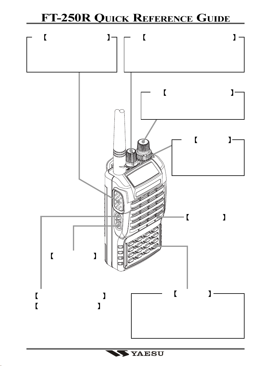
TRANSMISSION SWITCH
Speak into the microphone
in a normal voice level while
pressing the PTT switch.
POWER SWITCH AND VOL KNOB
Rotate the VOL/PWR knob to turn the
radio on and adjust the Audio Volume
Level.
FREQUENCY DIAL KNOB
Rotate the DIAL Knob to select the
operating frequency.
SQL KNOB
Adjusts to the point
where the background
noise is muted.
LAMP SWITCH
MONITOR SWITCH (USA)
T. CALL SWITCH (EXP)
MICROPHONE
LOCK KEY
Press and hold in the [F/L] key for
one second to lock all key functions
except the VOL, SQL Knobs, PTT,
T.CALL, and LAMP Switchs.

KEY OVERVIEW
Frequency entry digit “1.”
Press Key
Press [F/L] + Key
Activates the CTCSS or DCS Operation.
Frequency entry digit “2.”
Frequency entry digit “3.”
Frequency entry digit “4.”
Frequency entry digit “5.”
Frequency entry digit “6.”
Frequency entry digit “7.”
Frequency entry digit “8.”
Frequency entry digit “9.”
Frequency entry digit “0.”
Sets the frequency control to the
Memory Recall mode.
Activates the “Memory “Tune” mode
while in the Memory Recall mode.
Sets frequency control to the VFO mode.
Toggles the VFO between “VFO A” and
“VFO B” while in the VFO mode.
Increasser the VFO frequency by one
step or moves the memory channel to the
next-highest channel.
Decreases the VFO frequency by one
step or moves the memory channel to the
next-lowest channel.
Reverses the transmit and receive frequencies while working through a repeater.
Activates the “Alternate” key function.
Selects the CTCSS tone or DCS code
number.
Selects the desired transmit power output level.
Selects the direction of the uplink frequency shift during repeater operation.
Selects the CTCSS/DCS Bell ringer repetitions.
Toggles the display indication between
“frequency” and the channel’s “Alpha/
Numeric Tag”.
Activates the ARTS feature.
Activates the Smart Search feature.
Selects the DTMF Mode.
Engages the Set (Menu) Mode.
Selects the Memory Scan “Skip” channel-selection mode.
Activates the Priority (Dual Watch) function.
Tunes the VFO frequency upward in 1
MHz steps.
Tunes the VFO frequency downward in
1 MHz steps.
Switches to the “Home” (favorite frequency) Channel.
Disables the “Alternate” key function.
Press & Hold Key
Activates the Key Lockout feature.

Introduction
The FT-250R is an ultra compact FM hand-held providing up to five watts of RF power
and a wealth of convenient features for the 2m amateur band. The FT-250R has rubber
gasket seals around all external controls and connectors to help keep out dust and rain or
spray, assuring years of reliable operation even in harsh environments.
Sixteen multi-function keys provide the ultimate in programmability, with 199 freely tunable memories and two VFOs. All memories store repeater shifts or separate tx/rx frequencies, CTCSS (Continuous Tone Controlled Squelch System) or DCS status. You also
get one instant-recall “Home” channel memory and ten special purpose memories for
limited subband tuning/scanning. Busy channel band or selective memory scanning is
provided along with priority channel monitoring; 1 MHz up/down stepping; ARS (automatic repeater shift) when tuned to repeater subbands; plus a top panel rotary dial for
memory and frequency selection. The keypad serves as a DTMF encoder during transmission, and up to 9 DTMF memories can store 16 digits each for quick playback of commonly used numbers.
The liquid crystal display shows seven frequency digits, memory selection, CTCSS tone
frequency, and includes a bargraph S/PO meter. Yaesu’s power saver system can be set by
the operator for optimum sampling/standby ratio, or can be turned off for packet operation. And our new APO (Automatic Power Off) system shuts off the transceiver to avoid
dead batteries if you doze off or are called away unexpectedly.
Operation under difficult conditions is simplified by a lamp button illuminating the display and backlit translucent keypad, diatonically assigned function-dependent keypad beeps.
Please read this manual carefully to gain a full understanding of the features of the
FT-250R.
FT-250R OPERATING MANUAL 1
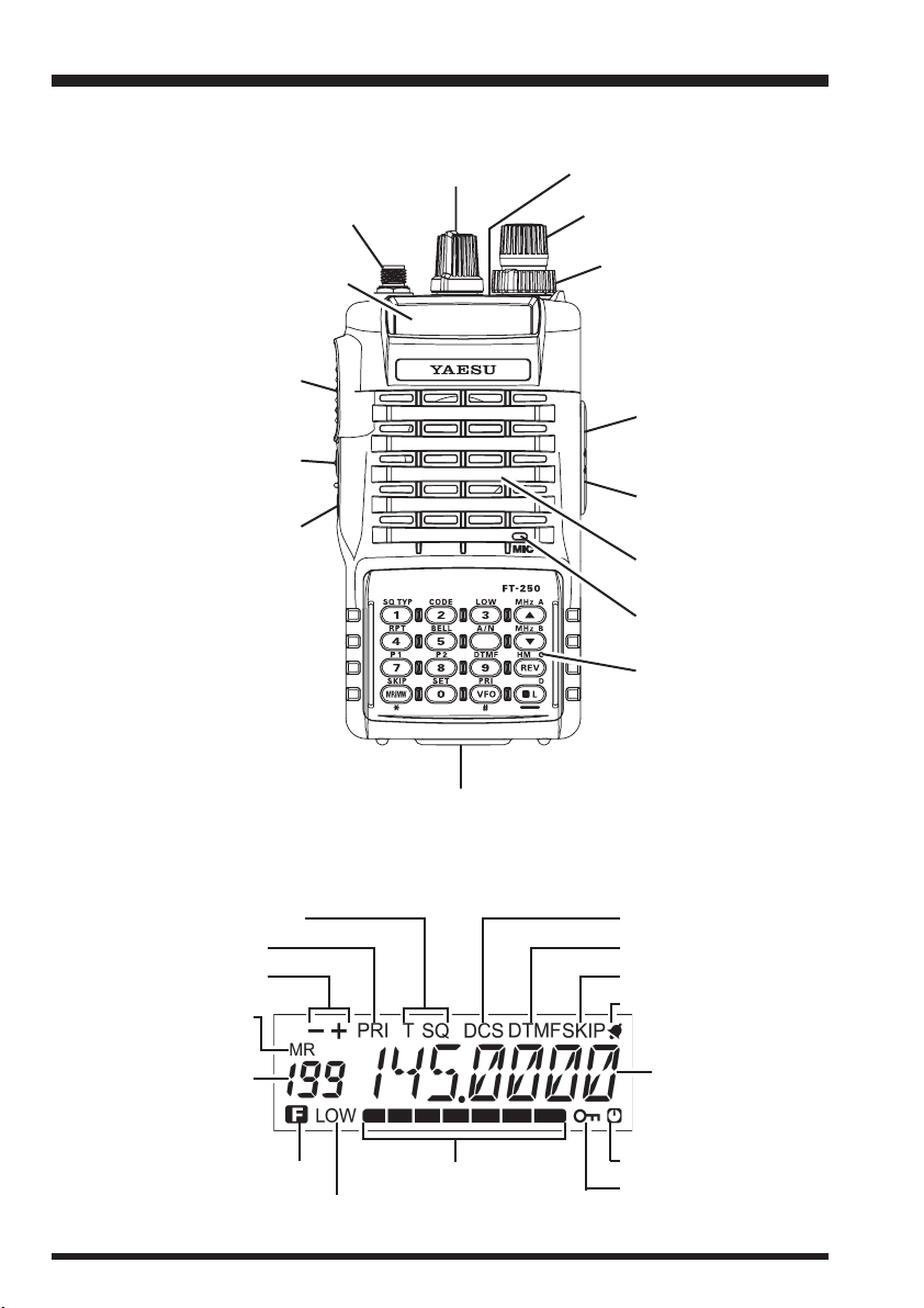
Controls & Connectors
ANTENNA Jack
LCD (Liquid Crystal Display)
PTT Button
Monitor (T.CALL) Button
LAMP Button
VOL/PWR Knob
Battery Pack Latch
BUSY/TX Indicator Lamp
DIAL Rotary Selector
SQL Control
MIC/SP Jack
EXT DC Jack
Speaker
Microphone
Keypad
Tone Encoder/Squelch Enabled
Priority Channel Scanning
Repeater Shift
Memory Mode
Memory Number
VFO Selection
or
Alt Key Active
LOW Power
S- and TX Power Meter
FT-250R OPERATING MANUAL2
Digital Coded Squelch
DTMF Memory Mode
Memory Skip
BELL
Frequency
Auto Power OFF Active
LOCK Feature Active

Accessories & Options
ACCESSORIES SUPPLIED WITH THE FT-250R
FNB-83 Ni-MH Battery Pack (7.2 V, 1400 mAh)
PA-38 AC Adapter
CD-30 Desktop Charger
Belt Clip
Antenna
Operating Manual
Warranty Card
AVAILABLE OPTIONS FOR YOUR FT-250R
FNB-83 7.2 V, 1400 mAh Ni-MH Battery Pack
FBA-25A Compact Dry Cell Battery Case for 6 AA-size cells
PA-38 AC Adapter
CD-30 Desktop Charger
B4B
MH-34
A4B
MH-37
VC-25 VOX Headset
CT-27 Cloning Cable
E-DC-5B DC Cable w/Noise Filter
E-DC-6 DC Cable; plug and wire only
CN-3 BNC-to-SMA Adapter
CT-44 Microphone Adapter
CSC-77 Soft Case
Speaker/Microphone
Earpiece/Microphone
Availability of accessories may vary: some accessories are supplied as standard per local
regulations and requirements, others may be unavailable in some regions. Check with
your Yaesu dealer for additions to the above list.
FT-250R OPERATING MANUAL 3
Basic Operation
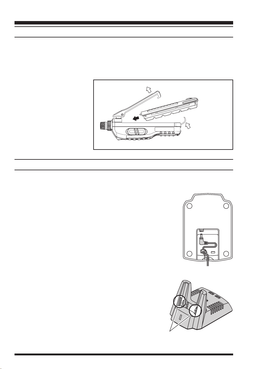
BATTERY PACK INSTALLATION AND REMOVAL
To install the battery, hold the transceiver with your left hand, so your palm is over the
speaker and your thumb is on the top of the belt clip. Insert the battery pack into the
battery compartment on the back of the radio while tilting the Belt Clip outward, then
close the Battery Pack Latch until it locks in place with a “Click.” To remove the battery,
turn the radio off and remove any protective cases. Open the Battery Pack Latch on the
bottom of the radio, then slide
the battery downward and out
from the radio while unfolding the Belt Clip.
Do not attempt to open any of
the rechargeable Ni-MH
packs, as they could explode
if accidentally short-circuited.
BATTERY CHARGING
If the battery has never been used, or its charge is depleted, it may be charged by connecting the PA-38/CD-30 Desktop Charger.
Tilt the Belt Clip
Insert the Battery Pack
Close the
Battery Pack Latch
Insert the DC plug from the PA-38 AC Adapter into the DC
c
jack on the bottom side of the CD-30 Desktop Charger, then
plug the PA-38 AC Adapter into the AC line outlet.
Insert the battery pack into the CD-30 Desktop Charger while
d
aligning the slots of the battery pack with the guides in the nest
of the CD-30; refer to the illustration below for details on proper
positioning of the pack. If charging with the transceiver attached, turn the transceiver off, and the antenna jack should be
at the left side when viewing the charger from the front.
If the battery pack is inserted correctly, the LED indicator will
e
glow red (Charging).
A fully-discharged pack will be charged completely in
approximately 3 hours.
When charging is completed, the red LED indicator will
f
change to green (Fully Charged). Disconnect the pack
from the CD-30 Desktop Charger, and unplug the PA-
38 AC Adapter from the AC line outlet.
FT-250R OPERATING MANUAL4
Align the slots of the battery pack
with the guides in the nest of the
CD-30 Desktop Charger.
Basic Operation
Important Notes!
Do not connect an improper AC Adapter. Use only the supplied PA-38 AC Adapter.
Do not charge an improper battery (one not specifically designed for use in the
PA-38/CD-30).
Disconnect the pack from the CD-30 Desktop Charger, and unplug the PA-38 AC
Adapter from the AC line outlet, when charging is completed.
The PA-38 AC Adapter and/or CD-30 Desktop Charger will generate a moderate
amount of heat during the charging process. This is a normal condition.
The PA-38/CD-30 is designed for charging only, and is not designed for operation
(transmission/reception) of the transceiver.
Periodically wipe the charging terminals in the nest in the charger stand, using a dry
cloth, to ensure good connections between the charger and battery.
Caution!!
When charging a battery pack alone (not attached to the transceiver), do not allow any
metal object to short the terminals on top of the pack.
Do not allow any metal objects to short the terminals in the nest of the charger stand,
as a short-circuit could cause overheating of the charger circuitry.
ANTENNA INSTALLATION
The supplied antenna provides good results over the entire frequency range of the transceiver. However, for enhanced coverage in remote areas, an external mobile or base station antenna may prove beneficial.
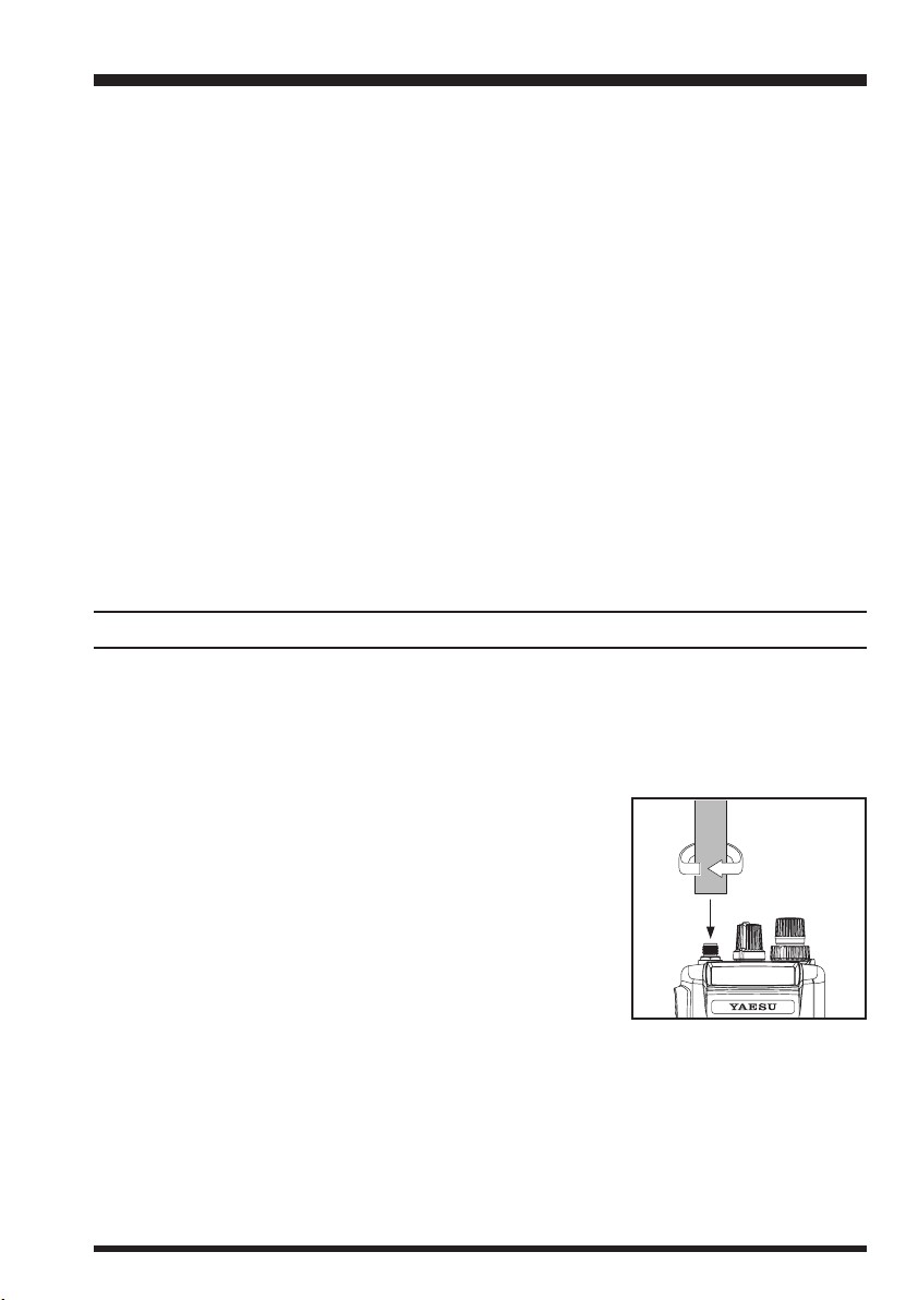
To install the supplied antenna
Hold the bottom end of the antenna, then screw it onto the
mating connector on the transceiver until it is snug. Do not
over-tighten by use of extreme force.
Notes:
Never transmit without having an antenna connected.
When installing the supplied antenna, never hold the
upper part of the antenna while screwing it onto the
mating connector on the transceiver.
If using an external antenna for transmission, ensure that the SWR presented to the
transceiver is 1.5:1 or lower, to avoid excessive feedline loss.
FT-250R OPERATING MANUAL 5

Basic Operation
SWITCHING POWER ON AND OFF
Be sure the battery pack is installed.
c
Connect the antenna to the top panel ANTENNA jack.
d
Switch on the transceiver by rotating the VOL control
e
clockwise out of the click-stop (a momentary beep will
sound).
ADJUSTING THE VOLUME LEVEL
Rotate the VOL control (immediately to the right of the Antenna) to set the desired audio
level. Clockwise rotation increases the volume level.
SQUELCH SETUP
Set the SQL control fully counterclockwise, rotate the VOL
control out of the click-stop and adjust for a comfortable
volume on the noise or received signal. The BUSY/TX
indicator LED should glow green. If a signal is present,
rotate the DIAL selector on the top panel to a channel where
only noise is heard.
Adjust the SQL control just to the point where the noise is
silenced and the LED is extinguished. If the SQL control is set further clockwise, sensitivity to weak signals will be reduced. Now, whenever a signal reaches the receiver that is
strong enough to open the squelch, the indicator will glow green.
TRANSMITTING
When you wish to transmit, wait until the channel is clear (BUSY/TX lamp off), and
squeeze the PTT switch. During transmission the BUSY/TX indicator glows red, and
relative transmitter power output is indicated graphically along the bottom of the display.
Release the PTT switch to receive.
If using a “B” version (in Europe), press the
T-CALL switch (just below the PTT switch)
to transmit a 1750 Hz tone to access repeaters that require it.
TX
RX
T-CALL
FT-250R OPERATING MANUAL6
Basic Operation
FREQUENCY NAVIGATION
]
Press the [VFO(PRI
two VFOs, labeled “A” and “B,” either of which can be used for all of the procedures
described in this manual. You can change VFOs with the [VFO(PRI
There are several ways to tune the FT-250R: in selectable channel steps or 1 MHz steps
with the [(MHz
Use the DIAL knob to tune the displayed VFO frequency at the current channel step rate.
You can also press the [(MHz
To change the MHz range of the VFO, you can press the [F/L] key followed by an [(MHz
[
or
[
(
MHz
seconds.
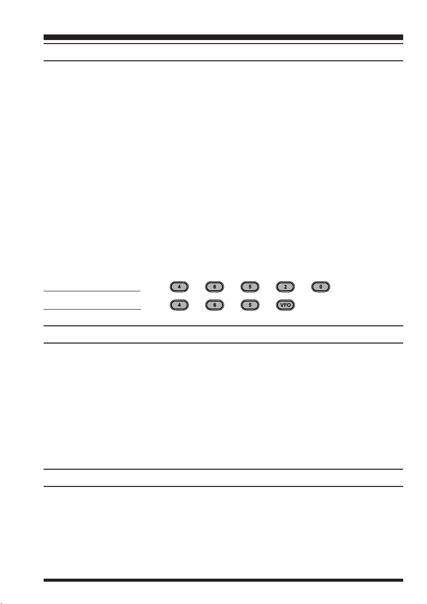
You can also enter a frequency directly just by keying in the 10 MHz, 1 MHz and the kHz
digits. Partial entries can be completed using the [VFO(PRI
Examples:
To enter 146.5200 MHz, press
To enter 146.5000 MHz, press
]
(
)
MHz
]
)
keys when moving up or down. When done, press [F/L] again, or just wait five
)
button, if necessary, to select the VFO mode. The FT-250R has
]
)
button at any time.
]
[
)
/
key (or turn the DIAL knob). Note the beeps when using the [(MHz
(
MHz
]
)
keys or DIAL knob, and direct keypad frequency entry.
]
[
)
/
(
MHz
]
)
keys momentarily to do this.
]
)
key.
]
)
]
)
/
CHANGING THE TRANSMITTER POWER LEVEL
You can select between a total of three transmitter power levels on your FT-250R. The
exact power output will vary somewhat, depending on the voltage supplied to the transceiver. With the standard FNB-83 Battery Pack, the power output levels available are:
HIGHHIGH
HIGH: 5 W
HIGHHIGH
MIDMID
MID: 2 W
MIDMID
LOWLOW
LOW: 0.5 W
LOWLOW
To change the power level:
]
Press the [F/L] key, then immediately press the [3(LOW
c
Now rotate the DIAL knob to select “
d
Press the PTT key to save the new setting and exit to normal operation.
e
LOWLOW
LOW”, “
LOWLOW
MIDMID
MID,” or “
MIDMID
)
key.
HIGHHIGH
HIGH”.
HIGHHIGH
CHANGING THE CHANNEL STEPS
To change a frequency step, follow the procedure below:
]
Press the [F/L] key, then immediately press the [0(SET
c
Rotate the DIAL to select Menu Item #6 (“
d
Press the [F/L] key to enable modification of the current setting.
e
Now rotate the DIAL knob to select 5, 10, 12.5, 15, 20, 25 or 50 kHz steps.
f
Press the PTT key to save the new setting and exit to normal operation.
g
STEPSTEP
STEP”).
STEPSTEP
FT-250R OPERATING MANUAL 7
)
key to enter the Set mode.
Basic Operation
REPEATER OPERATION
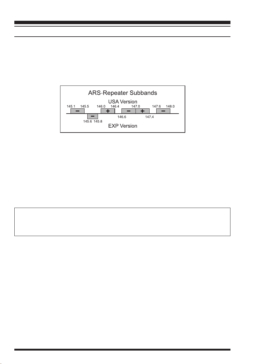
The ARS (Automatic Repeater Shift) feature in the FT-250R provides repeater shift of
the transmit frequency whenever you are tuned to a standard repeater subband (see diagram below). When enabled, a small “–” or “+” will be displayed in the upper left-hand
corner of the display, signifying that repeater shift is active, and closing the push-to-talk
switch changes the display to the (shifted) transmit frequency.
Automatic Repeater Shift (ARS)
To re-enable ARS:
]
Press the [F/L] key, then immediately press the [0(SET
c
Rotate the DIAL to select Menu Item #2 (“
d
Press the [F/L] key to enable modification of the current setting.
e
Now rotate the DIAL to select “ON” (to enable Automatic Repeater Shift).
f
Press the PTT key to save the new setting and exit to normal operation.
g
ARSARS
ARS”).
ARSARS
)
key to enter the Set mode.
Tone Burst
For repeaters using 1750-Hz burst tone access, you can configure the switch below
the PTT to send the access tone when this switch is pressed. See page 14 for details.
Manual Repeater Shift Activation
When a repeater shift is active, either “–” or “+” appears in the display. If neither appears
when tuned to a repeater output frequency, you can activate the shift manually:
]
Press the [F/L] key, then immediately press the [0(SET
c
Rotate the DIAL to select Menu Item #3 (“
d
Press the [F/L] key to enable modification of the current setting.
e
Rotate the DIAL to select the desired repeater shift direction (
f
Press the PTT key to save the new setting and exit to normal operation.
g
RPTRPT
RPT”).
RPTRPT
)
key to enter the Set mode.
-RPT-RPT
-RPT,
-RPT-RPT
+RPT+RPT
+RPT or
+RPT+RPT
SIMPSIMP
SIMP).
SIMPSIMP
FT-250R OPERATING MANUAL8

Basic Operation
Setting repeater Tx Offset
Although you should keep the repeater offset programmed to that used in your area, you
can change the default repeater offset for special applications:
]
Press the [F/L] key, then immediately press the [0(SET
c
Rotate the DIAL to select Menu Item #4 (“
d
Press the [F/L] key to enable modification of the current setting.
e
Rotate the DIAL to select the new shift offset frequency (selectable in 50-kHz incre-
f
ments only).
Press the PTT key to save the new setting and exit to normal operation.
g
SHIFTSHIFT
SHIFT”).
SHIFTSHIFT
Checking the Repeater Uplink (Input) Frequency
It often is helpful to be able to check the uplink (input) frequency of a repeater, to see if the
calling station is within direct (“Simplex”) range.
]
To do this, just press the [REV(HM
has been set to “
the normal uplink/downlink frequency relationship, repeat this step.
HMHM
HM,” you may press the [F/L] key, and then [REV(HM
HMHM
)
key momentarily. If Menu Item #20 (“
KEYBOARD LOCKING
To activate the locking feature, press and hold in the [F/L] key for one second. The “ ”
icon will appear on the LCD. To cancel locking press and hold in the [F/L] key again for
one second.
In order to prevent accidental frequency change or inadvertent transmission, various aspects of the FT-250R’s DIAL, keypad and switches may be locked out. You may change
the lockout combinations.
To lock out some or all of the keys:
]
Press the [F/L] key, then press the [0(SET
c
Rotate the DIAL to select Menu Item #32 (“
d
Press the [F/L] key to enable setting of the Lock mode (which defines which keys/
e
functions are to be locked out).
Rotate the DIAL to the desired locking scheme as listed below:
f
KEYKEY
KEY: Just the front panel keys are locked out
KEYKEY
DIALDIAL
DIAL: Just the top panel DIAL is locked out
DIALDIAL
KK
D D
KEYKEY
K +
D (
KK
D D
PTTPTT
PTT: The PTT switch is locked (TX not possible)
PTTPTT
KK
P P
K +
P (
KK
P P
DD
P P
D +
P (
DD
P P
ALLALL
ALL: All of the above are locked out
ALLALL
When you have made your selection, press the PTT key momentarily to save the new
g
setting and resume normal operation.
DIALDIAL
KEY +
DIAL) : Both the DIAL and Keys are locked out
KEYKEY
DIALDIAL
KEYKEY
PTTPTT
KEY +
PTT) : Both the keys and PTT switch are locked out
KEYKEY
PTTPTT
DIALDIAL
DIAL +
DIALDIAL
PTTPTT
PTT) : Both the DIAL and PTT switch are locked out
PTTPTT
)
key to enter the Set mode.
LK MODELK MODE
LK MODE”).
LK MODELK MODE
)
key to enter the Set mode.
REVREV
REV/
REVREV
]
)
key. To return to
HMHM
HM”)
HMHM
FT-250R OPERATING MANUAL 9

Advanced Operation
VFO SPLIT MODE
For working on repeaters with odd splits, or communicating with astronauts on orbiting
space vehicles, it may be necessary to use non-standard splits between the receive and
transmit frequency. If the application is infrequent enough not to warrant the dedication of
a memory channel for this purpose, the “VFO Split” mode may be used. Here is the procedure:
]
Press the [VFO(PRI
c
frequency (for example, 144.950 MHz).
Now press the [VFO(PRI
d
(e.g. 144.750 MHz).
Press the [VFO(PRI
e
VFO.
Press the [F/L] key, then press the [0(SET
f
Rotate the DIAL to select Menu #5 (“
g
Press the [F/L] key, then rotate the DIAL to set this function ON.
h
Press the PTT key once to save the new setting and exit to normal operation.
i
You will now be operating in a Split mode. When you press the PTT key to transmit,
j
you will observe that VFO-A and VFO-B will reverse positions.The VFO selection
indicator “
Split feature is now activated.
If you need to modify the VFO-B (transmit) frequency (for Doppler Shift correction,
k
etc.), just press the [VFO(PRI
[
VFO(PRI
When you have finished with Split operation, re-enter the Set mode, and set Menu #5
l
to OFF.
bb
b” will blinks while the transceiver is transmitting, this means that the VFO
bb
]
)
key once more to restore VFO-A to the “receive VFO” position.
)
key, as needed, to select VFO-A. Set VFO-A for the receiving
]
)
key, and set VFO-B for the desired transmit frequency
]
)
key once more to re-establish VFO-A as the “Main” (receive)
]
)
key, to enter the Set mode.
V-SPLITV-SPLIT
V-SPLIT”).
V-SPLITV-SPLIT
]
)
key, then make the necessary change, then press
A split frequency pair set up via the VFO Split feature cannot be stored directly into
memory. You can, however, store odd frequency pairs using a different (slightly simpler)
procedure. See page 18.
RECEIVE BATTERY SAVER SETUP
An important feature of the FT-250R is its Receive Battery Saver, which “puts the radio
to sleep” for a time interval, periodically “waking it up” to check for activity. If somebody
is talking on the channel, the FT-250R will remain in the “active” mode, then resume its
“sleep” cycles. This feature significantly reduces quiescent battery drain, and you may
change the amount of “sleep” time between activity checks using the Menu System:
]
Press the [F/L] key, then press the [0(SET
c
Rotate the DIAL to select Menu Item #9 (“
d
Press the [F/L] key to enable adjustment of this Menu item.
e
)
key to enter the Set mode.
RX SAVERX SAVE
RX SAVE”).
RX SAVERX SAVE
FT-250R OPERATING MANUAL10
 Loading...