


FM TRANSCEIVER
FT-2900R
OPERATING MANUAL
VERTEX STANDARD CO., LTD.
4-8-8 Nakameguro, Meguro-Ku, Tokyo 153-8644, Japan
VERTEX STANDARD
US Headquarters
10900 Walker Street, Cypress, CA 90630, U.S.A.
YAESU UK LTD.
Unit 12, Sun Valley Business Park, Winnall Close
Winchester, Hampshire, SO23 0LB, U.K.
VERTEX STANDARD HK LTD.
Unit 5, 20/F., Seaview Centre, 139-141 Hoi Bun Road,
Kwun Tong, Kowloon, Hong Kong
VERTEX STANDARD (AUSTRALIA) PTY., LTD.
Normanby Business Park, Unit 14/45 Normanby Road Notting Hill 3168, Victoria, Australia

Contents
FT-2900R Quick Reference Guide |
|
Introduction ...................................................... |
1 |
Specifications .................................................... |
2 |
Accessories & Options ...................................... |
3 |
Supplied Accessories ..................................... |
3 |
Optional Accessories ...................................... |
3 |
Installation ........................................................ |
4 |
Preliminary Inspection ................................... |
4 |
Installation Tips .............................................. |
4 |
Safety Information .......................................... |
5 |
Antenna Considerations ................................. |
6 |
Mobile Installation ......................................... |
7 |
Mobile Power Connections ........................ |
8 |
Mobile Speakers ......................................... |
8 |
Base Station Installation ................................. |
9 |
AC Power Supplies .................................... |
9 |
Front Panel Controls & Switches .................. |
10 |
Microphone Switches ..................................... |
12 |
Rear Panel Connectors ................................... |
13 |
Basic Operation .............................................. |
14 |
Turning the Transceiver On and Off ............ |
14 |
Adjusting the Audio Volume Level ............. |
14 |
Adjusting the Squelch Setting ...................... |
14 |
Frequency Navigation .................................. |
15 |
1) Tuning Dial .......................................... |
15 |
2) Direct Keypad Frequency Entry .......... |
15 |
3) Scanning .............................................. |
15 |
Transmission ................................................ |
16 |
Changing the Transmitter Power Level ... |
16 |
Advanced Operation ...................................... |
17 |
Weather Broadcast Reception ...................... |
17 |
Lock Feature ................................................. |
18 |
Keyboard Beeper .......................................... |
18 |
Channel Step Selection ................................ |
19 |
Display Brightness ....................................... |
19 |
RF Squelch ................................................... |
20 |
Repeater Operation ....................................... |
21 |
Standard Repeater Shift ........................... |
21 |
Automatic Repeater Shift (ARS) ............. |
22 |
CTCSS/DCS/EPCS Operation ..................... |
23 |
CTCSS Operation .................................... |
23 |
DCS Operation ......................................... |
25 |
Tone Search Scanning .............................. |
26 |
EPCS Operation ....................................... |
27 |
CTCSS/DCS/EPCS Bell Paging .............. |
29 |
Split Tone Operation ................................ |
30 |
DTMF Operation .......................................... |
32 |
Manual DTMF Tone Generation ............. |
32 |
DTMF Autodialer .................................... |
32 |
Memory Operation ......................................... |
34 |
Memory Storage ........................................... |
34 |
Separate Transmit Frequency Memory |
|
(“Odd Splits”) ...................................... |
35 |
Memory Recall ............................................. |
36 |
Labeling Memories ...................................... |
37 |
Memory Tuning ............................................ |
38 |
Masking Memories ....................................... |
38 |
Memory Bank Operation .............................. |
39 |
Assigning Memories to a Memory Bank . 39 |
|
Memory Bank Recall ............................... |
39 |
Removing Memories |
|
from a Memory Bank ........................... |
40 |
Changing a Memory Bank’s Name .......... |
40 |
HOME Channel Memory ............................. |
41 |
Memory Only Mode ..................................... |
42 |
Scanning .......................................................... |
44 |
Basic Scanner Operation .............................. |
44 |
Scan-Resume Option .................................... |
45 |
Memory Skip Scanning ................................ |
46 |
Preferential Memory Scan ............................ |
47 |
Memory Bank Link Scan ............................. |
48 |
Programmable Band-Scan Limits ................. |
49 |
Priority Channel Scanning (Dual Watch) ..... |
50 |
Priority Revert Mode ............................... |
50 |
Weather Alert Scan ...................................... |
51 |
Band Edge Beeper ........................................ |
51 |
Smart Search Operation ................................ |
52 |
Internet Connection Feature ......................... |
54 |
SRG Mode .................................................... |
54 |
FRG Mode .................................................... |
54 |
ARTS™ ........................................................... |
57 |
Basic ARTS™ Setup and Operation ............ |
57 |
ARTS™ Polling Time Options .................... |
58 |
ARTS™ Alert Beep Options ........................ |
58 |
CW Identifier Setup ..................................... |
59 |
CW Training Feature ..................................... |
60 |
Packet Operation ............................................ |
61 |
Miscellaneous Settings .................................... |
62 |
Password ...................................................... |
62 |
Time-Out Timer ........................................... |
63 |
Automatic Power-Off ................................... |
63 |
Busy Channel Lock-Out ............................... |
64 |
Programming the Key Assignments ............. |
65 |
FM Bandwidth & TX Deviation Level ........ |
66 |
MIC Gain Setting ......................................... |
66 |
DCS Code Inversion .................................... |
67 |
Reset Procedure .............................................. |
68 |
Microprocessor Resetting ............................. |
68 |
Set Mode Resetting ...................................... |
68 |
Cloning ............................................................ |
69 |
“Set” (Menu) Mode ........................................ |
70 |
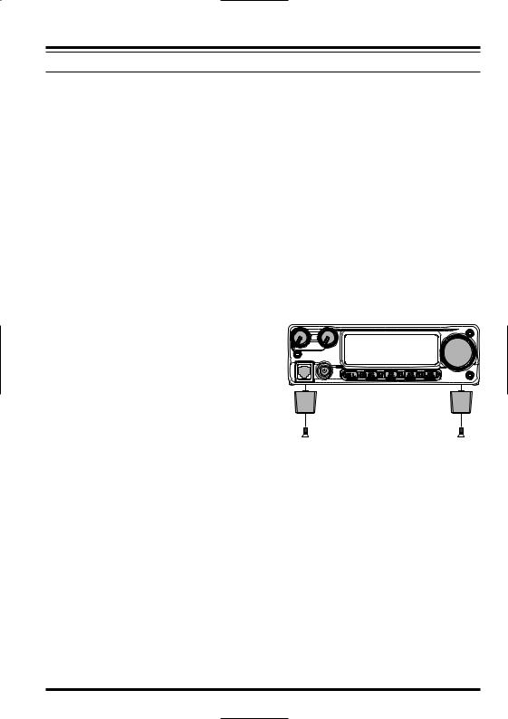
FT-2900R QUICK REFERENCE GUIDE
|
|
VOL KNOB |
|
|
|
|
|
|
|
|
|
|
|
|
|
|
|
|
|
|
|
|
|
SQL KNOB |
|
|
|
|||||||||||||||
|
|
|
|
|
|
|
|
|
|
|
|
|
|
|
|
|
|
|
|
|
|
|
|
|
|
|||||||||||||||||
Adjusts the audio |
|
|
|
|
Adjust to the point where the |
|||||||||||||||||||||||||||||||||||||
volume level. |
|
|
|
|
background noise is muted. |
|||||||||||||||||||||||||||||||||||||
|
|
|
|
|
|
|
|
|
|
|
|
|
|
|
|
|
|
|
|
|
|
|
|
|
|
|
|
|
|
|
|
|
|
|
FREQUENCY DIAL KNOB |
|
||||||
|
|
|
|
|
|
|
|
|
|
|
|
|
|
|
|
|
|
|
|
|
|
|
|
|
|
|
|
|
|
|
|
|
|
|
|
|||||||
|
|
|
|
|
|
|
|
|
|
|
|
|
|
|
|
|
|
|
|
|
|
|
|
|
|
|
|
|
Selects the operating Frequency. |
|||||||||||||
|
|
|
|
|
|
|
|
|
|
|
|
|
|
|
|
|
|
|
|
|
|
|
|
|
|
|
|
|
|
|
|
|
|
|
|
|
|
|
|
|
|
|
|
|
|
|
|
|
|
|
|
|
|
|
|
|
|
|
|
|
|
|
|
|
|
|
|
|
|
|
|
|
|
|
|
|
|
|
|
|
|
|
|
|
|
|
|
|
|
|
|
|
|
|
|
|
|
|
|
|
|
|
|
|
|
|
|
|
|
|
|
|
|
|
|
|
|
|
|
|
|
|
|
|
|
|
|
|
|
|
|
|
|
|
|
|
|
|
|
|
|
|
|
|
|
|
|
|
|
|
|
|
|
|
|
|
|
|
|
|
|
|
|
|
|
|
|
|
|
|
|
|
|
|
|
|
|
|
|
|
|
|
|
|
|
|
|
|
|
|
|
|
|
|
|
|
|
|
|
|
|
|
|
|
|
|
|
|
|
|
|
|
|
|
|
|
|
|
|
|
|
|
|
|
|
|
|
|
|
|
|
|
|
|
|
|
|
|
|
|
|
|
|
|
|
|
|
|
|
|
|
|
|
|
|
|
|
|
|
|
|
|
|
|
|
|
|
|
|
|
|
|
|
|
|
|
|
|
|
|
|
|
|
|
|
|
|
|
|
|
|
|
|
|
|
|
|
|
|
|
|
|
|
|
|
|
|
|
|
|
|
|
|
|
|
|
|
|
|
|
|
|
|
|
|
|
|
|
|
|
|
|
|
|
|
|
|
|
|
|
|
|
|
|
|
|
|
|
|
|
|
|
|
|
|
|
|
|
|
|
|
|
|
|
|
|
|
|
|
|
|
|
|
|
|
|
|
|
|
|
|
|
|
|
|
|
|
|
|
|
|
|
|
|
|
|
|
|
|
|
|
|
|
|
|
|
|
|
|
|
|
|
|
|
|
|
|
|
|
|
|
|
|
|
|
|
|
|
|
|
|
|
|
|
|
|
|
|
|
|
|
|
|
|
|
|
|
|
|
|
|
|
|
|
|
|
|
|
|
|
|
|
|
|
|
|
|
|
|
|
|
|
|
|
|
|
|
|
|
|
|
|
|
|
|
|
|
|
|
|
|
|
|
|
|
|
|
|
|
|
|
|
|
|
|
|
|
|
|
|
|
|
|
|
|
|
|
|
|
|
|
|
|
|
|
|
|
|
|
|
|
|
|
|
|
|
|
|
|
|
|
|
|
|
|
|
|
|
|
|
|
|
|
|
|
|
|
|
|
|
|
|
|
|
|
|
|
|
|
|
|
|
|
|
|
|
|
|
|
|
|
|
|
|
|
|
|
|
|
|
|
|
|
|
|
|
|
|
|
|
|
|
|
|
|
|
|
|
|
|
|
|
|
|
|
|
|
|
|
|
|
|
|
|
|
|
|
|
|
|
|
|
|
|
|
|
|
|
|
|
|
|
|
|
|
|
|
|
|
|
|
|
|
|
|
|
|
|
|
|
|
|
|
|
|
|
|
|
|
|
|
|
|
|
|
|
|
|
|
|
|
|
|
|
|
|
|
|
POWER SWITCH |
|
|
|
LOCK SWITCH |
|
|
|
|
|
|||
|
Press and hold for |
|
Press and hold for one second to lock all |
|||
|
one second. |
|
key functions except the VOL, SQL knobs |
|||
|
|
|
|
and PTT switch. |
||
|
|
|
|
|
|
|
TRANSMISSION SWITCH |
MICROPHONE |
|
Speak into the microphone |
||
|
||
in a normal voice level |
|
|
while pressing this switch. |
|
FT-2900R QUICK REFERENCE GUIDE
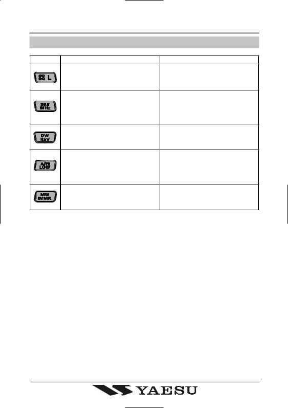
KEY OVERVIEW
KEY |
PRESS KEY BRIEFLY |
PRESS AND HOLD KEY |
|
Activates the Internet Connec- |
Locks out the switches and |
|
tion Feature. |
knobs (except the VOL, SQL |
|
|
knobs and PTT switch). |
|
Allows tuning the VFO fre- |
Enters the Set (“Menu”) mode. |
|
quency in 1-MHz steps, or tun- |
|
|
ing channels in 10 channel |
|
|
steps. |
|
|
Reverses transmit and receive |
Activates the Priority Channel |
|
frequencies in repeater opera- |
Scanning (Dual Watch fea- |
|
tion. |
ture). |
|
Selects the transmitter power |
Toggles the display indication |
|
output level. |
between “frequency” and the |
|
|
channel’s “Alpha/Numeric |
|
|
Tag”. |
|
Switches the frequency control |
Transfers the VFO contents |
|
between the VFO, Memory Sys- |
into a Memory register. |
|
tem, and the Home channel. |
|

INTRODUCTION
The Yaesu FT-2900R is a deluxe, rugged FM mobile transceiver providing high power output and outstanding receiver performance for the 144 MHz Amateur band. Included in the FT-2900R’s feature complement are:
75 Watts of power output, with selection of four power levels for every operating situation.
Expanded receiver coverage: 136-174 MHz.
Keyboard entry of operating frequencies from the microphone.
Excellent protection from receiver intermodulation distortion, thanks to Yaesu’s renowned Advanced Track Tuning front end.
221 memories (200 “basic” memory channels, 10 sets of band-edge memory channels, and one “Home” channel) which can store repeater shifts, odd repeater shifts, CTCSS/ DCS tones, and 6-character Alpha-Numeric labels for easy channel recognition.
10 NOAA Weather Broadcast Channels, with Weather Alert and a Volume Control for the Weather Alert tone.
Built-in CTCSS and DCS Encoder/Decoder circuits.
The Smart SearchTM feature, which automatically sweeps a band and loads active frequencies into dedicated memory banks, is ideal for identifying active repeaters when visiting a city for the first time.
Extensive Menu system, which allows customization of a number of transceiver performance characteristics.
The Yaesu-exclusive multi-function LCD display.
Additional features include a transmit Time-Out-Timer (TOT), Automatic Power-Off (APO), Automatic Repeater Shift (ARS), plus provision for reduction of the Tx deviation in areas of high channel congestion. And an RF Squelch circuit allows the owner to set the squelch to open at a programmable setting of the S-Meter, thus reducing guesswork in setting the squelch threshold.
Congratulations on your purchase of the FT-2900R! Whether this is your first rig, or if Yaesu equipment is already the backbone of your station, the Vertex Standard organization is committed to ensuring your enjoyment of this high-performance transceiver, which should provide you with many years of satisfying operation. Our dealer network and technical support personnel stand behind every product we sell, and we invite you to contact us should you require technical advice or assistance.
We recommend that you read this manual in its entirety prior to installing the FT-2900R, so that you fully understand the capabilities of your new transceiver.
FT-2900R OPERATING MANUAL |
1 |

SPECIFICATIONS
General
Frequency Range: |
Tx 144 - 146 MHz or 144 - 148 MHz |
Channel Step: |
Rx 144 - 148 MHz or 136 - 174 MHz |
5/10/12.5/15/20/25/50/100 kHz |
|
Standard Repeater Shift: |
±600 kHz |
Frequency Stability: |
Better than ±10 ppm |
Modes of Emission: |
[–4 °F to +140 °F (–20 °C to +60 °C)] |
F2D/F3E |
|
Antenna Impedance: |
50 Ohms, unbalanced |
Supply voltage: |
13.8 V DC ±15 %, negative ground |
Current Consumption (typical): Rx: less than 0.7 A, less than 0.3 A (squelched) |
|
|
Tx: 15 A (75 W) /9 A (30 W) /5 A (10 W) /4 A (5 W) |
Operating Temperature Range: –4° F to +140° F (–20° C to +60° C) |
|
Case Size (WxHxD): |
6.3” x 2” x 7.3” (160 x 50 x 185 mm) (w/o knobs) |
Weight (Approx.): |
4 .2 lb (1.9 kg) |
Transmitter
Output Power: |
75 W/30 W/10 W/5 W |
Modulation Type: |
Variable Reactance |
Maximum Deviation: |
±5 kHz (Wide) |
Spurious Radiation: |
±2.5 kHz (Narrow) |
Better than –60 dB |
|
Microphone Impedance: |
2 k-Ohms |
Receiver
Circuit Type: |
Double Conversion Superheterodyne |
Ifs: |
21.7 MHz & 450 kHz |
Sensitivity (for 12dB SINAD): |
Better than 0.4 µV |
Selectivity (–6/–60dB): |
12 kHz/28 kHz (Wide) |
IF Rejection: |
9 kHz/22 kHz (Narrow) |
Better than 70 dB |
|
Image Rejection: |
Better than 70 dB |
Maximum AF Output: |
3 W into 4 Ohms @10 % THD |
Specifications subject to change without notice or obligation. Specifications guaranteed only within Amateur band.
Frequency ranges will vary according to transceiver version; check with your dealer.
2 |
FT-2900R OPERATING MANUAL |

|
A CCESSORIES & O PTIONS |
|
|
S UPPLIED A CCESSORIES |
|
Microphone MH-48A6J |
...................................................................................................... |
1 |
Mobile Mounting Bracket MMB-83 .................................................................................. |
1 |
|
DC Power Cord w/Fuse ..................................................................................(T9021015) |
1 |
|
Spare Fuse 25A (Q0000074) .............................................................................................. |
2 |
|
Standing Foot ...................................................................................................................... |
|
1 |
Operating Manual ............................................................................................................... |
|
1 |
Warranty Card..................................................................................................................... |
|
1 |
|
O PTIONAL A CCESSORIES |
|
High-Power External Speaker MLS-100 |
|
|
AC Power Supply |
FP - 1023 (25 A: USA only) |
|
AC Power Supply |
FP - 1030A (25 A) |
|
Availability of accessories may vary. Some accessories are supplied as standard per local requirements, while others may be unavailable in some regions. This product is designed to perform optimally when used with genuine Vertex Standard accessories. Vertex Standard shall not be liable for any damage to this product and/or accidents such as fire, leakage or explosion of a battery pack, etc., caused by the malfunction of nonVertex Standard accessories. Consult your Vertex Standard dealer for details regarding these and any newlyavailable options. Connection of any non-Vertex Standard-approved accessory, should it cause damage, may void the Limited Warranty on this apparatus.
FT-2900R OPERATING MANUAL |
3 |

INSTALLATION
This chapter describes the installation procedure for integrating the FT-2900R into a typical amateur radio station. It is presumed that you possess technical knowledge and conceptual understanding consistent with your status as a licensed radio amateur. Please take some extra time to make certain that the important safety and technical requirements detailed in this chapter are followed closely.
PRELIMINARY INSPECTION
Inspect the transceiver visually immediately upon opening the packing carton. Confirm that all controls and switches work freely, and inspect the cabinet for any damage. Gently shake the transceiver to verify that no internal components have been shaken loose due to rough handling during shipping.
If any evidence of damage is discovered, document it thoroughly and contact the shipping company (or your local dealer, if the unit was purchased over-the-counter) so as to get instructions regarding the prompt resolution of the damage situation. Be certain to save the shipping carton, especially if there are any punctures or other evidence of damage incurred during shipping; if it is necessary to return the unit for service or replacement, use the original packing materials but put the entire package inside another packing carton, so as to preserve the evidence of shipping damage for insurance purposes.
INSTALLATION TIPS
To ensure long life of the components, be certain to provide adequate ventilation around the cabinet of the FT-2900R.
Do not install the transceiver on top of another heat-generating device (such as a power supply or amplifier), and do not place equipment, books, or papers on top of the FT-2900R. Avoid heating vents and window locations that could expose the transceiver to excessive direct sunlight, especially in hot climates. The FT-2900R should not be used in an environment where the ambient temperature exceeds +140 °F (+60 °C).
4 |
FT-2900R OPERATING MANUAL |
INSTALLATION
SAFETY INFORMATION
The FT-2900R is an electrical apparatus, as well as a generator of RF (Radio Frequency) energy, and you should exercise all safety precautions as are appropriate for this type of device. These safety tips apply to any device installed in a well-designed amateur radio station.
Never allow unsupervised children to play in the vicinity of your transceiver or

 antenna installation.
Be certain to wrap any wire or cable splices thoroughly with insulating electrical

 tape, to prevent short circuits.
Do not route cables or wires through door jambs or other locations where, through

 wear and tear, they may become frayed and shorted to ground or to each other.
 Do not stand in front of a directional antenna while you are transmitting into that
 antenna. Do not install a directional antenna in any location where humans or pets
may be walking in the main directional lobe of the antenna’s radiation pattern.
 In mobile installations, it is preferable to mount your antenna on top of the roof of
 the vehicle, if feasible, so as to utilize the car body as a counterpoise for the antenna
and raise the radiation pattern as far away from passengers as possible.
During vehicular operation when stopped (in a parking lot, for example), make it a

 practice to switch to Low power if there are people walking nearby.
  Never wear dual-earmuff headphones while driving a vehicle.
 Do not attempt to drive your vehicle while making a telephone call on an autopatch
 using the DTMF microphone. Pull over to the side of the road, whether dialing
manually or using the auto-dial feature.
FT-2900R OPERATING MANUAL |
5 |

INSTALLATION
ANTENNA CONSIDERATION
The FT-2900R is designed for use with antennas presenting an impedance of near 50 Ohms at all operating frequencies. The antenna (or a 50 Ohm dummy load) should be connected whenever the transceiver is turned on, to avoid damage that could otherwise result if transmission occurs accidentally without an antenna.
Ensure that your antenna is designed to handle 75 Watts of transmitter power. Some mag- netic-mount mobile antennas, designed for use with hand-held transceivers, may not be capable of withstanding this power level. Consult the antenna manufacturer’s specification sheet for details.
Most all FM work is performed using vertical polarization. When installing a directional antenna such as a Yagi or Cubical Quad, be certain to orient it so as to produce vertical polarization, unless you are engaged in a special operating situation where horizontal polarization is used. In the case of a Yagi antenna, orient the elements vertically for vertical polarization; for a Cubical Quad, the feedpoint should be at the center of one of the vertical sides of the driven element (or at a side corner, in the case of a diamond-shaped “Delta Loop”).
Excellent reference texts and computer software are available for the design and optimization of VHF antennas. Your dealer should be able to assist you with all aspects of your antenna installation requirements.
Use high-quality 50 Ohm coaxial cable for the lead-in to your FT-2900R transceiver. All efforts at providing an efficient antenna system will be wasted if poor quality, lossy coaxial cable is used. Losses in coaxial lines increase as the frequency increases, so an 8-meter- long (25’ coaxial line with 1/2 dB of loss at 29 MHz may have a loss of 1.8 dB or more at 146 MHz; choose your coaxial cable carefully based on the installation location (mobile vs. base) and the overall length of the cable required (for very short runs of cable in a mobile installation, the smaller, more flexible cable types may be acceptable).
For reference, the chart at the right shows ap- |
Loss in dB per 30 m (100 feet) for |
||
proximate loss figures for typically-available |
Selected 50-Ohm Coaxial Cables |
||
coaxial cables frequently used in VHF instal- |
(Assumes 50-ohm Input/Output Terminations) |
||
lations. |
CABLE TYPE |
LOSS: 144 MHZ |
|
In outdoor installations, be certain to weather- |
RG-58A |
6.5 |
|
RG-58 Foam |
4.7 |
||
RG-213 |
3.0 |
||
proof all connectors thoroughly, as water en- |
|||
RG-8 Foam |
2.0 |
||
tering a coaxial cable will cause losses to esca- |
Belden 9913 |
1.5 |
|
late rapidly, thus diminishing your communi- |
Times Microwave LMR-400 |
1.5 |
|
7/8” “Hardline” |
0.7 |
||
cations effectiveness. The use of the shortest |
|||
Loss figures are approximate; consult cable manufac- |
|||
possible length of the highest quality coaxial |
turers’ catalogs for complete specifications. |
||
cable that fits within your budget will ensure the best performance from your FT-2900R.
6 |
FT-2900R OPERATING MANUAL |
INSTALLATION
MOBILE INSTALLATION
The FT-2900R must only be installed in vehicles having a 13.8 Volt negative ground electrical system. Mount the transceiver where the display, controls, and microphone are easily accessible, using the supplied MMB-83 mounting bracket.
The transceiver may be installed in almost any location, but should not be positioned near a heating vent nor anywhere where it might interfere with driving (either visually or mechanically). Make sure to provide plenty of space on all sides of the transceiver so that air can flow freely around the radio’s case. Refer to the diagrams showing proper installation procedures.
MMB-83 Installation
FT-2900R OPERATING MANUAL |
7 |
INSTALLATION
MOBILE INSTALLATION
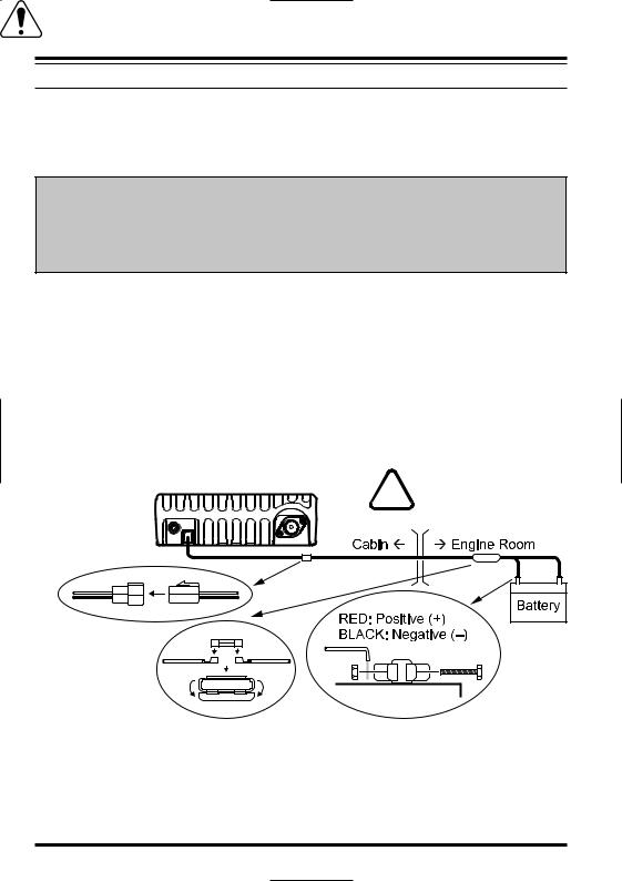
Mobile Power Connections
To minimize voltage drop and avoid blowing the vehicle’s fuses, connect the supplied DC power cable directly to the battery terminals. Do not attempt to defeat or bypass the DC cable’s fuse - it is there to protect you, your transceiver, and your vehicle’s electrical system.
Warning!
Never apply AC power to the power cable of the FT-2900R, nor DC voltage greater than 15.8 Volts. When replacing the fuse, only use a 25-A fuse. Failure to observe these safety precautions will void the Limited Warranty on this product.
Before connecting the transceiver, check the voltage at the battery terminals while revving the engine. If the voltage exceeds 15 Volts, adjust the vehicle’s voltage regulator before proceeding with installation.
Connect the RED power cable lead to the POSITIVE (+) battery terminal, and the BLACK power cable lead to the NEGATIVE (–) terminal. If you need to extend the power cable, use #12 AWG or larger insulated, stranded copper wire. Solder the splice connections carefully, and wrap the connections thoroughly with insulating electrical tape.
Before connecting the cable to the transceiver, verify the voltage and polarity of the voltage at the transceiver end of the DC cable using a DC voltmeter. Now connect the
transceiver to the DC cable.
WARNING!
FT-2900R |
NEVER remove the FUSE |
holders from the DC cable. |
Fuse 25 A
Fuse Holder
Mobile Speakers
The optional MLS-100 External Speaker includes its own swivel-type mounting bracket, and is available from your Yaesu dealer.
Other external speakers may be used with the FT-2900R, if they present the specified 4-Ohm impedance and are capable of handling the 3 Watts of audio output supplied by the FT-2900R.
8 |
FT-2900R OPERATING MANUAL |
INSTALLATION
BASE STATION INSTALLATION
The FT-2900R is ideal for base station use as well as in mobile installations. The FT2900R is specifically designed to integrate into your station easily, using the information to follow as a reference.
AC Power Supplies
Operation of the FT-2900R from an AC line requires a power source capable of providing at least 11 Amps continuously at 13.8 Volts DC. The FP-1023 and FP-1030A AC Power Supplies are available from your Yaesu dealer to satisfy these requirements. Other wellregulated power supplies may be used, as well, if they meet the above voltage and current specifications.
Use the DC power cable supplied with your transceiver for making power connections to the power supply. Connect the RED power cable lead to the POSITIVE (+) power supply terminal, and connect the BLACK power cable lead to the NEGATIVE (–) power supply terminal.
Base Station Feet
The supplied Base Station Feet allow the transceiver to be tilted upward for better viewing.
To install the Base Station Feet, remove the two screws affixing the front side of the bottom cover, then install the Base Station Feet using these screws.
FT-2900R OPERATING MANUAL |
9 |
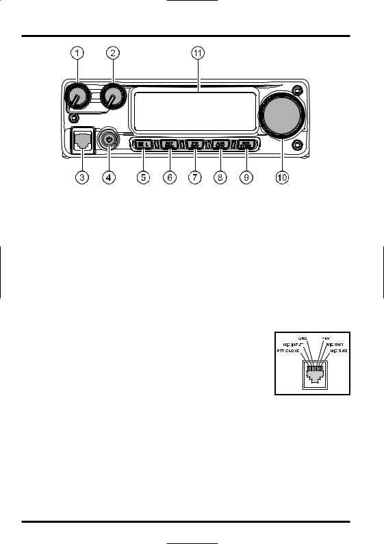
FRONT PANEL CONTROLS & SWITCHES
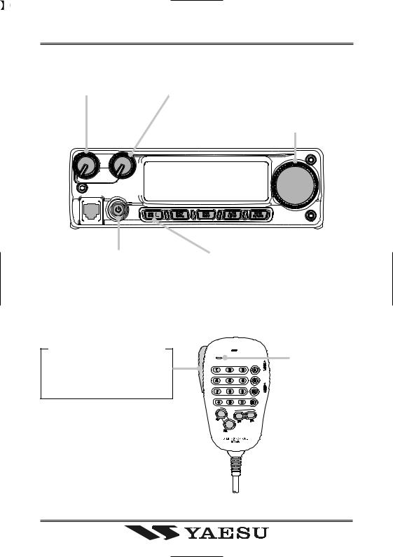
 VOL Knob
This control adjusts the audio volume level. Clockwise rotation increases the volume level.
 SQL Knob
This control is used to silence background noise on the receiver. It should be advanced clockwise just to the point where the noise is silenced (and the “ ” indicator on the display turns off), so as to provide the best sensitivity to weak signals.
 Microphone Jack
Connect the supplied MH-48A6J Hand Microphone to this jack.
 PWR Key
Press and hold this key for one second to toggle the transceiver’s power on and off.
 [
[
 (L)] Key
This key allows operation in conjunction with the Internet Connection feature.
Press and hold in this key for one second to toggle the Lockout Feature “on” or “off”.
 [MHz(SET)] Key
This key allows tuning in 1-MHz steps (the MHz digits will blink on the display). If receiving on a memory, pressing this key the first time activates the Memory Tuning mode, and pressing it again enables 1-MHz steps.
Press and hold in this key for one second to activate the “Set” (Menu) mode.
10 |
FT-2900R OPERATING MANUAL |
FRONT PANEL CONTROLS & SWITCHES
 [REV(DW)] Key
During split-frequency operation, such as through a repeater, this key reverses the transmit and receive frequencies.
Press and hold in this key for one second to activate the Dual Watch feature, described in the Operation chapter (“PRI” will be displayed on the LCD, indicating “Priority Channel” monitoring).
 [LOW(A/N)] Key
Press this key momentarily to select the transmitter power output level. The available power levels are:
LOW1 (5 W) Æ LOW2 (10 W) Æ LOW3 (30 W) Æ HIGH (75 W)
To toggle the display between indication of the frequency and the channel’s Alpha/ Numeric label, press and hold in this key for one second while receiving on that memory channel.
 [D/MR(MW)] Key
Press this key momentarily to switch the frequency control among the VFO, Memory System, and Home channel.
Press and hold in this key for one second to activate the Memory Storage mode.
 DIAL Knob
This 24-position detented rotary switch is used for tuning, memory selection and most function settings. The microphone [UP]/[DWN] buttons duplicate the functions of this knob.
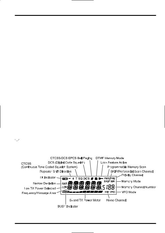
 Display
The main digits on the display may show the operating frequency, memory name, or any of many parameters during Menu setup.
FT-2900R OPERATING MANUAL |
11 |
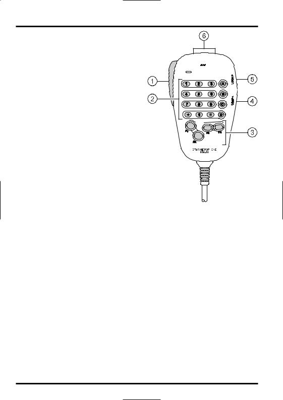
MICROPHONE SWITCHES
 PTT Switch
Press this switch to transmit, and release it
to receive.
 Keypad
These 16 keys generate DTMF tones during transmission. In the receive mode, these 16 keys can be
used for direct frequency entry and/or direct numeric recall of the Memory channels.
The [A], [B], [C], and [D] keys, on receive,
replicate the functions of the front panel keys ([MHz(SET)], [REV(DW)], [LOW(A/N)], and [D/MR(MW)]). See the previous discus-
sion.
 [P1]/[P2]/[P3]/[P4] Buttons
These four keys are user programmable, allowing quick access to features used often. The default functions are described below. [P1] button (SQL OFF)
Press this button to disable the noise and tone squelch systems. [P2] button (S SRCH)
Press this button to activate the Smart Search feature. [P3] button (C SRCH)
Press this button to activate the Tone Search feature. [P4] button (WX CH/T.CALL)
In the USA version, pressing this button recalls the “Weather” broadcast channel bank. In the EXP version, pressing this button activates T.CALL (1750 Hz) for repeater access. You can reprogram the [P1], [P2], [P3], and [P4] buttons for other functions, if desired. See page 65 for details.
 LAMP Switch
This switch illuminates the Microphone’s keypad.
 LOCK Switch
This switch locks out the Microphone’s buttons (except for the keypad and PTT switch).
 [UP]/[DWN] Button
Press (or hold in) either of these buttons to tune (or scan up or down) the operating frequency or through the memory channels. In many ways, these buttons emulate the function of the (rotary) DIAL knob.
12 |
FT-2900R OPERATING MANUAL |
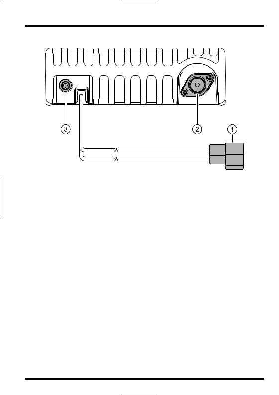
REAR PANEL CONNECTORS
 13.8V DC Cable Pigtail
This is the power supply connection for the transceiver. Use the supplied DC cable to connect this pigtail to the car battery or other DC power supply capable of at least 15 Amperes (continuous duty). Make certain that the red lead connects to the positive side of the supply. The fuse is 25A.
 ANT Coaxial Socket
Connect a 144-MHz antenna to this type-M (SO-239) socket using 50-Ohm coaxial cable and a type-M (PL-259) plug. Make sure the antenna is designed specifically for use on the operating frequency.
 EXT SP Jack
This 2-contact 3.5-mm mini phone jack provides receiver audio output for an optional external speaker. The audio impedance is 4 Ohms, and the level varies according to the setting of the front panel’s VOL control. Inserting a plug into this jack disables audio from the transceiver’s internal speaker.
FT-2900R OPERATING MANUAL |
13 |

BASIC OPERATION


 Hi! I’m R. F. Radio, and I’ll be helping you along as you learn the many features


 of the FT-2900R. I know you’re anxious to get on the air, but I encourage you to read the “Basic Operation” section of this manual as thoroughly as possible, so you’ll get
the most out of this fantastic new transceiver. Now. . .let’s get operating!
TURNING THE TRANSCEIVER ON AND OFF
1. To turn the transceiver on, press and hold in the PWR key for one second.
When you turn on the FT-2900R, the current DC supply voltage is indicated on the LCD for 2 seconds. After this interval, the display will switch its normal indication of the operating frequency.
2.To turn the transceiver off, again press and hold in the PWR key for one second.
You can change the Opening Message (DC supply voltage indication) to any desired message (up to 6 characters) via Set Mode Item “31 OPN.MSG;” see page
76 for details.
ADJUSTING THE AUDIO VOLUME LEVEL
Rotate the VOL control to adjust the receiver volume. Clockwise rotation increases the audio output level.
ADJUSTING THE SQUELCH SETTING
Rotate the SQL control just to the point where the noise is silenced and the “ ” indicator on the display turns off. If the SQL control is set further clockwise, sensitivity to weak signals is reduced.
A special “RF Squelch” feature is provided on this radio. This feature allows you to set the squelch so that only signals exceeding a certain S-meter level will open the squelch. See page 20 for details
14 |
FT-2900R OPERATING MANUAL |
BASIC OPERATION
FREQUENCY NAVIGATION
1) Tuning Dial
Rotating the DIAL knob allows tuning in the pre-programmed steps. Clockwise rotation of the DIAL knob causes the FT-2900R to be tuned toward a higher frequency, while counter-clock- wise rotation will lower the operating frequency.
Press the [MHz(SET)] key momentarily, then rotate the DIAL knob, to change the frequency steps to 1 MHz per step. This feature is extremely useful for making rapid frequency excursions over the wide tuning range of the FT-2900R. Instead of pressing the [MHz(SET)] button, you may also press the [A] key on the Microphone’s keypad to engage tuning in 1 MHz steps.
2) Direct Keypad Frequency Entry
The keypad of the MH-48A6J DTMF Microphone may be used for direct entry of the operating frequency.
To enter a frequency from the MH-48A6J keypad, just press the numbered digits in the proper sequence. There is no “decimal point” key on the MH-48A6J keypad. However, there is a short-cut for frequencies ending in zero: press the [#] key after the last non-zero digit.
Examples: To enter 146.520 MHz, press [1] Æ [4] Æ [6] Æ [5] Æ [2] Æ [0] To enter 146.000 MHz, press [1] Æ [4] Æ [6] Æ [#]


 If you cannot get the radio to accept the frequency entry, it is possible that the


 channel steps are set to an incompatible value (e.g. if you have 25 kHz steps set, you cannot set a frequency of 146.520 MHz). See page 19 to learn how to change the channel step size.
3) Scanning
From the VFO mode, press the microphone’s [UP]/[DWN] keys momentarily to initiate scanning toward a higheror lower frequency, respectively. The FT-2900R will stop when it receives a signal strong enough to break through the squelch threshold. The FT-2900R will then hold on that frequency according to the setting of the “Resume” mode (Menu “41 SCAN)”; see page 45).
If you wish to reverse the direction of the scan (i.e. toward a lower frequency, instead of a higher frequency), just rotate the DIAL knob one click in the counter-clockwise direction while the FT-2900R is scanning. The scanning direction will be reversed. To revert to scanning toward a higher frequency once more, rotate the DIAL knob one click clockwise.
Press the [UP]/[DWN] keys again to cancel scanning. You may also press the PTT button momentarily; scanning will stop, but you will not transmit until you release the PTT button, and press it again.
If you have enabled the “Severe Weather Alert” feature, you will occasionally notice “WX” channels interspersed with the regular channels you are scanning. This
is normal, because your radio is constantly monitoring for weather alerts. See page 17.
FT-2900R OPERATING MANUAL |
15 |
BASIC OPERATION
TRANSMISSION
To transmit, simply close the PTT (Push To Talk) switch on the microphone when the frequency is clear. Hold the microphone approximately 1” (25 mm) from your mouth, and speak into the microphone in a normal voice level. When your transmission is complete, release the PTT switch; the transceiver will revert to the receive mode.
During transmission, the “ ” indicator will appear at the upper left corner on the display.
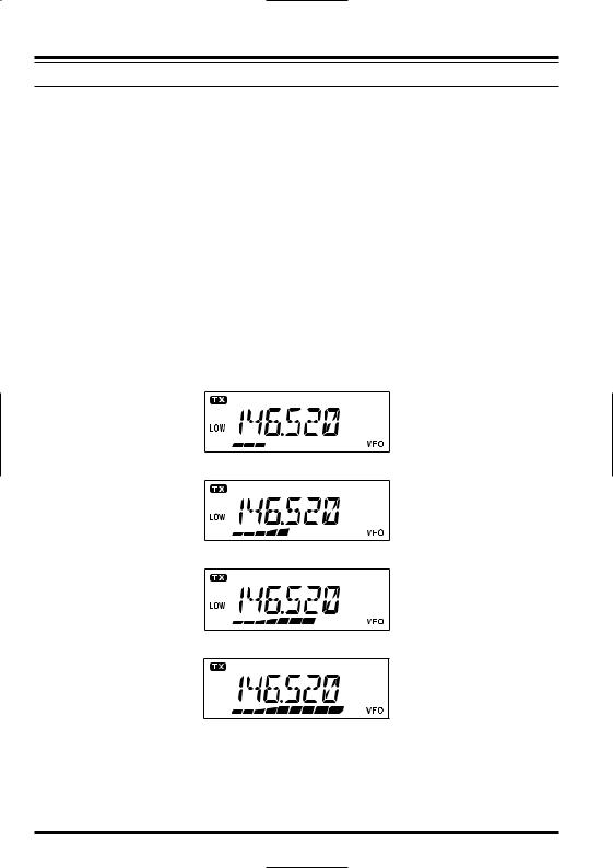
Changing the Transmitter Power Level
You can select from among a total of four transmit power levels on your FT-2900R.
To change the power level, press the [LOW(A/N)] key (or the microphone’s [C] key to select one of four power settings. These power levels will be stored, in memory registers, at the time of memory storage (see page 34 for details on Memory operation).
During transmission, the Bar Graph will deflect in the display, according to the power output selected.
Low 1 (5 watts)
Low 2 (10 watts)
Low 3 (30 watts)
HIGH (75 watts)
16 |
FT-2900R OPERATING MANUAL |
ADVANCED OPERATION
WEATHER BROADCAST RECEPTION (USA VERSION)
The FT-2900R includes a unique feature which allows reception of weather broadcasts in the 160-MHz frequency range. Ten standard Weather Broadcast channels are pre-loaded into a special memory bank.
To listen to a Weather Broadcast Channel:
1. Press the Microphone’s [P4] button to recall the Weather Broadcast channels.
2.Turn the DIAL knob to select the desired Weather Broadcast channel.
3. If you wish to check the other channels for activity by scanning, just press the Microphone’s PTT
switch.
4. To exit to normal operation, press the [P4] button again. Operation will return to the VFO or Memory
channel you were operating on before you began Weather Broadcast operation.


 The [P4] key, one of the programmable keys, is assigned (default setting) as the


 “WX Broadcast” one-touch access key. Please note that if you change/assign another function to the [P4] key, one-touch access to the WX channel will be unavailable.
Severe Weather Alert Feature
In the event of extreme weather disturbances, such as storms and hurricanes, NOAA (the National Oceanic and Atmospheric Administration) sends a weather alert accompanied by a 1050 Hz tone and subsequent weather report on one of the NOAA weather channels. You may enable this feature via Menu Item “57 WX ALT,” if desired. See page 49 for details.
When scanning the band or the “regular” memories, with the Severe Weather Alert feature engaged, you will notice that the FT-2900R will break over to the Weather Channel bank every five seconds, performing a quick scan of those channels in search for the 1050 Hz alert tone. If the alert tone is received, operation will lock on the weather broadcast station issuing the alert; otherwise, the radio will revert to the VFO or memory scan session in progress without interruption.
When the alert tone is received, press the PTT button momentarily to disable the alarm, and the Severe Weather message will now be audible from the speaker.
FT-2900R OPERATING MANUAL |
17 |
ADVANCED OPERATION
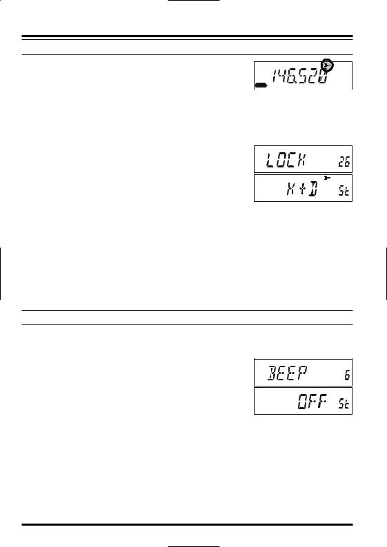
LOCK FEATURE
To activate the locking feature, press and hold in the [
 (L)]
(L)]
key for one second. The “ ” icon will appear on the LCD.
To cancel locking, press and hold in the [
 (L)] key again for
 one second.
In order to prevent accidental frequency change or inadvertent transmission, various aspects of the FT-2900R’s keys and knob may be locked out.
To lock out some or all of the keys, use the “Set” (Menu) mode, described below: 1. Press and hold in the [MHz(SET)] key for one second, then
rotate the DIAL knob to select “26 LOCK.” 2. Press the [MHz(SET)] key, then rotate the DIAL knob to
select the desired lockout combination. KEY: Just the front panel keys are locked out. DIAL: Just the front panel DIAL knob is locked out.
K+D: Both the keys and DIAL knob are locked out. PTT: The PTT switch is locked (TX not possible). K+P: Both keys and PTT switch are locked out.
D+P: Both DIAL knob and PTT switch are locked out. ALL: All of the above are locked out.
3.Press and hold in the [MHz(SET)] key for one second to save the new setting and exit to normal operation.
KEYBOARD BEEPER
A key/button beeper provides useful audible feedback whenever a key/button is pressed. If you want to turn the beeper off (or back on again):
1. Press and hold in the [MHz(SET)] key for one second, then rotate the DIAL knob to select “6 BEEP.”
2. Press the [MHz(SET)] key, then rotate the DIAL knob to set the display to “OFF.”
3. Press and hold in the [MHz(SET)] key for one second to save your new setting and exit to normal operation.
4.To turn the beep back on again, select “KEY” or “KY+SCN (factory default)” in step 4 above.
KEY: The beeper sounds when you press the keypad.
KY+SCN: The beeper sounds when you press the keypad, or when the scanner stops.
18 |
FT-2900R OPERATING MANUAL |
ADVANCED OPERATION
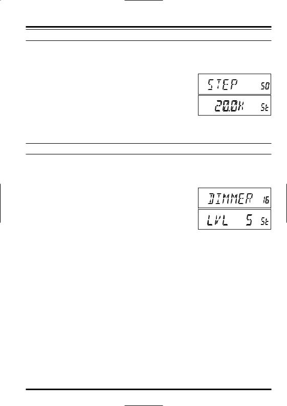
CHANNEL STEP SELECTION
Tuning steps are factory preset to default increments which are appropriate for the country to which this radio is exported. You may have a reason to use a different step size, however, and here is the procedure for changing the channel steps:
1. Press and hold in the [MHz(SET)] key for one second, then
rotate the DIAL knob to select “50 STEP.” 2. Press the [MHz(SET)] key, then rotate the DIAL knob to
select the desired step size (5/10/12.5/15/20/25/50/100 kHz).
3.Press and hold in the [MHz(SET)] key for one second to save your new setting and exit to normal operation.
DISPLAY BRIGHTNESS
The FT-2900R display illumination has been specially engineered to provide high visibility with minimal disruption of your “night vision” while you are driving. The brightness of the display is manually adjustable, using the following procedure:
1. Press and hold in the [MHz(SET)] key for one second, then
rotate the DIAL knob to select “16 DIMMER.” 2. Press the [MHz(SET)] key, then rotate the DIAL knob to
select a comfortable brightness level (LVL 0 - LVL10). 3. Press and hold in the [MHz(SET)] key for one second to
save your new setting and exit to normal operation.
FT-2900R OPERATING MANUAL |
19 |
ADVANCED OPERATION
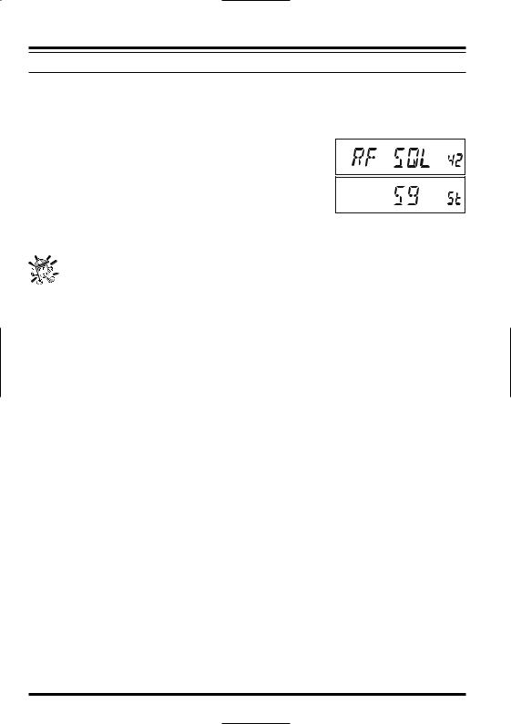
RF SQUELCH
A special RF Squelch feature is provided on this radio. This feature allows you to set the squelch so that only signals exceeding a certain S-meter level will open the squelch.
To set up the RF squelch circuit for operation, use the following procedure:
1. Press and hold in the [MHz(SET)] key for one second, then
rotate the DIAL knob to select “42 RF SQL.” 2. Press the [MHz(SET)] key, then rotate the DIAL knob to
select the desired signal strength level for the squelch threshold (S1 - S9 or OFF).
3.Press and hold in the [MHz(SET)] key for one second to save your new setting and exit to normal operation.
The receiver’s squelch will open based on the highest level set by the two squelch systems, “Noise Squelch” and “RF Squelch.” For example:
1)If the Noise Squelch (SQL control) is set so that signals at a level of S-3 will open the squelch, but the RF Squelch (Menu #42) is set to “S-9,” the squelch will only open on signals which are S-9 or stronger on the S-meter.
2)If the RF Squelch is set to “S-3,” but the Noise Squelch is set to a high level which will only pass signals which are Full Scale on the S-meter, the squelch will only open on signals which are Full Scale on the S-meter. In this case, the Noise Squelch overrides the action of the RF Squelch.
20 |
FT-2900R OPERATING MANUAL |
REPEATER OPERATION
The FT-2900R includes a host of convenience features which makes operation on amateur repeaters both efficient and enjoyable.
This transceiver offers three methods of setting up split-frequency operation on repeaters:
Manual selection of preset repeater shifts (Standard Repeater Shift);
Automatic Repeater Shift (ARS), providing automatic activation of repeater shifts while operating within designated repeater frequency subbands; and
Independently stored transmit and receive frequencies (typically not corresponding to established repeater frequency shifts).
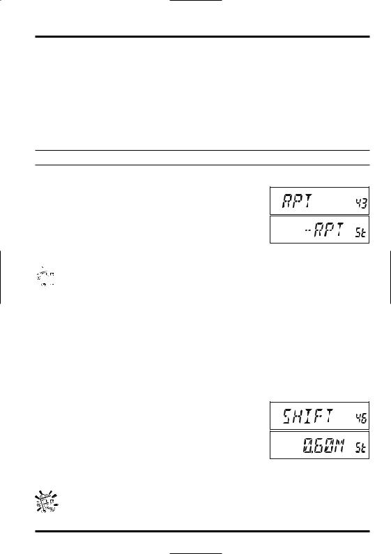
STANDARD REPEATER SHIFT
To activate the standard shift manually, you may use the Set (Menu) mode:
1. Press and hold in the [MHz(SET)] key for one second, then
rotate the DIAL knob to select “43 RPT.” 2. Press the [MHz(SET)] key, then rotate the DIAL knob to
select the desired shift direction (–RPT, +RPT, or SIMP). 3. Press and hold in the [MHz(SET)] key for one second to
save your new setting and exit to normal operation.


 You also may program one of the Microphone’s programmable keys ([P1] ~ [P4])


 to allow quick access to the above procedure. See page 65 for details on the setup
of the programmable keys.
With repeater shift activated, you can temporarily reverse the transmit and receive frequencies by pressing the [REV(DW)] key (or the microphone’s [B] key). Use this feature to display the transmit frequency without transmitting, and to check the strength of signals on a repeater uplink frequency (so as to determine whether or not a particular station is within “Simplex” range, for example).
The repeater offset is fixed to 600 kHz from the factory. You can change the offset by the following procedure, if needed for vacation travel or other purposes:
1. Press and hold in the [MHz(SET)] key for one second, then
rotate the DIAL knob to select “46 SHIFT.” 2. Press the [MHz(SET)] key, then rotate the DIAL knob to
set the desired offset. Note that the resolution of the “standard” repeater shift is to the nearest 50 kHz multiple.
3.Press and hold in the [MHz(SET)] key for one second to save your new setting and exit to normal operation.
Do not use this procedure for programming of an “odd split” type repeater pair! The process for programming odd splits is shown on page 35.
FT-2900R OPERATING MANUAL |
21 |
REPEATER OPERATION
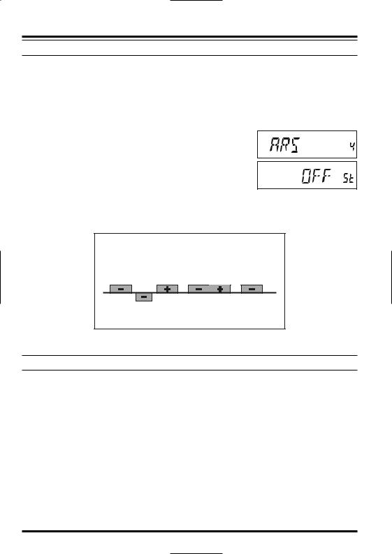
AUTOMATIC REPEATER SHIFT
The ARS (Automatic Repeater Shift) feature in this transceiver allows easy and convenient repeater operation by automatically activating the repeater shift function whenever you tune to a standard repeater subband. The ARS function is preset at the factory to conform to the standards for the country to which it is exported.
The ARS function is enabled at the factory. To disable it:
1. Press and hold in the [MHz(SET)] key for one second, then rotate the DIAL knob to select “4 ARS.”
2. Press the [MHz(SET)] key, then rotate the DIAL knob to change the display to “OFF.”
3. Press and hold in the [MHz(SET)] key for one second to save your new setting and exit to normal operation.
To enable the ARS function again, select “ON” in step 2 above.
ARS-Repeater Subbands
Version A
145.1 |
145.5 |
146.0 |
146.4 |
147.0 |
147.6 |
148.0 |
146.6 147.4
145.6 145.8
European Version
CHECKING THE REPEATER UPLINK (INPUT) FREQUENCY
It often is helpful to be able to check the uplink (input) frequency of a repeater, to see if the calling station is within direct (“Simplex”) range.
To do this, just press the [REV(DW)] key. You’ll notice that the display has shifted to the repeater uplink frequency. Press the [REV(DW)] key again to cause operation to revert to normal monitoring of the repeater downlink (output) frequency. While you are listening on the input frequency to the repeater using the [REV(DW)] key, the repeater offset icon will blink.
22 |
FT-2900R OPERATING MANUAL |
CTCSS/DCS/EPCS OPERATION
CTCSS OPERATION
Many repeater systems require that a very-low-frequency audio tone be superimposed on your FM carrier in order to activate the repeater. This helps prevent false activation of the repeater by radar or spurious signals from other transmitters. This tone system, called “CTCSS” (Continuous Tone Coded Squelch System), is included in your FT-2900R, and is very easy to activate.
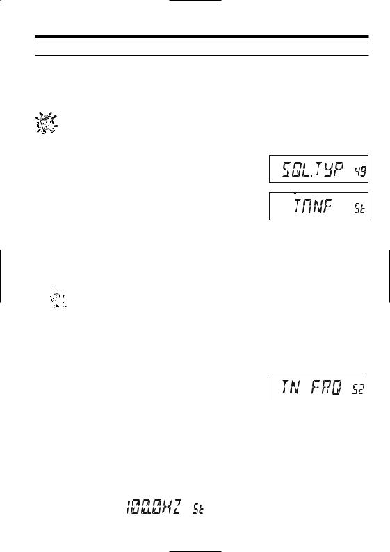
CTCSS setup involves two actions: setting the Tone Mode and then setting of the Tone Frequency. These actions are set up by using the Set (Menu) mode, selec-
tions #49 (SQL.TYP) and #52 (TN FRQ).
1. Press and hold in the [MHz(SET)] key for one second, then rotate the DIAL knob to select “49 SQL.TYP.”
2. Press the [MHz(SET)] key, then rotate the DIAL knob so that “TONE” appears on the display; this activates the CTCSS Encoder, which allows repeater access.
3.Rotating the DIAL knob one more click clockwise in the  above step will cause “TSQL” to appear. When “TSQL” appears, this means that the Tone Squelch system is active, which mutes your FT-2900R’s receiver until it receives a call from another radio sending out a matching CTCSS tone. This can help keep your radio quiet until a specific call is received, which may be helpful while operating in congested areas.


 1) You may notice a “RV TN” indication on the display while you rotate the


 DIAL knob in this step; this means that the Reverse Tone Squelch system is active, which mutes your FT-2900R’s receiver (instead of opening the squelch) when it receives a call from the radio sending a matched CTCSS tone. The “T SQ” icon will blink on the display when the Reverse Tone Squelch system is activated.
2) You may notice a “DCS” indication on the display while you rotate the DIAL knob still more. We’ll discuss the Digital Code Squelch system shortly.
4.When you have made your selection of the CTCSS tone
mode, press the [MHz(SET)] key momentarily, then ro- |
|
|
|
|
|
|
|||||||
tate the DIAL knob three clicks clockwise to select Menu |
|
|
|
|
|
|
|||||||
|
|
|
|
|
|
||||||||
“52 TN FRQ.” This Menu selection allows |
|
|
|
|
|
|
|
|
|
||||
|
CTCSS TONE FREQUENCY (Hz) |
|
|||||||||||
setting of the CTCSS tone frequency to be |
67.0 |
|
69.3 |
71.9 |
74.4 |
77.0 |
|
79.7 |
|||||
used. |
|
|
|
|
82.5 |
|
85.4 |
88.5 |
91.5 |
94.8 |
|
97.4 |
|
[ |
( |
|
)] |
|
100.0 |
|
103.5 |
107.2 |
110.9 |
114.8 |
|
118.8 |
|
5. Press the MHz SET |
key to enable adjust- |
|
|
|
|
|
|
|
|
|
|||
ment of the CTCSS frequency. |
123.0 |
|
127.3 |
131.8 |
136.5 |
141.3 |
|
146.2 |
|||||
151.4 |
|
156.7 |
159.8 |
162.2 |
165.5 |
|
167.9 |
||||||
6. Rotate the DIAL knob until the display in- |
|
|
|||||||||||
171.3 |
|
173.8 |
177.3 |
179.9 |
183.5 |
|
186.2 |
||||||
dicates the Tone Frequency you need to be |
|
|
|||||||||||
189.9 |
|
192.8 |
196.6 |
199.5 |
203.5 |
|
206.5 |
||||||
using. |
|
|
|
|
|
|
|||||||
|
|
|
|
210.7 |
|
218.1 |
225.7 |
229.1 |
233.6 |
|
241.8 |
||
|
|
|
|
|
250.3 |
|
254.1 |
|
– |
– |
– |
|
– |
|
|
|
|
|
|
|
|
|
|
|
|
|
|
|
|
|
|
|
|
|
|
|
|
|
|
|
|
FT-2900R OPERATING MANUAL |
23 |
 Loading...