

Page 1
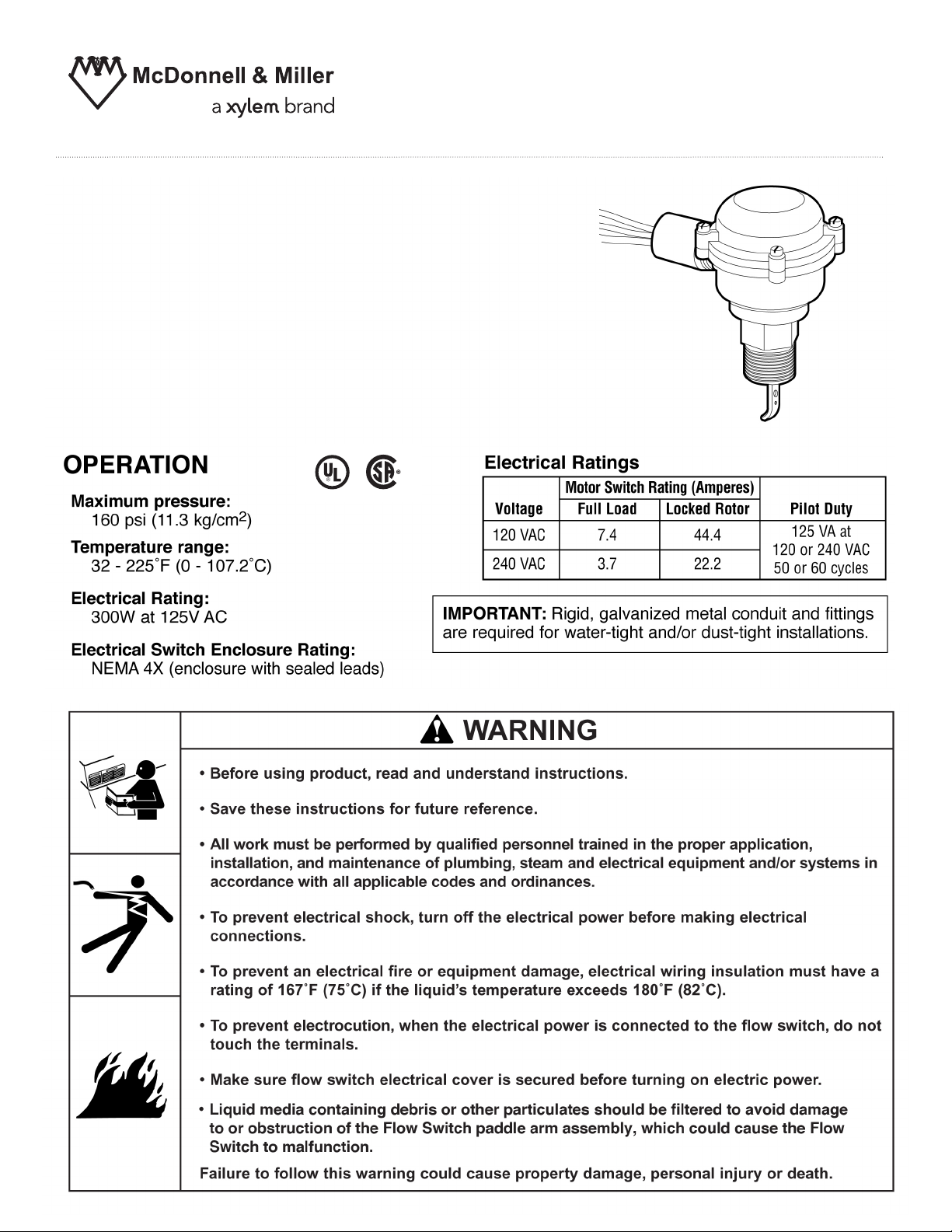
Model FS8-WG-SL
Flow Switch
INSTRUCTION MANUAL
MM-611 CC
C
Page 2
Page 3
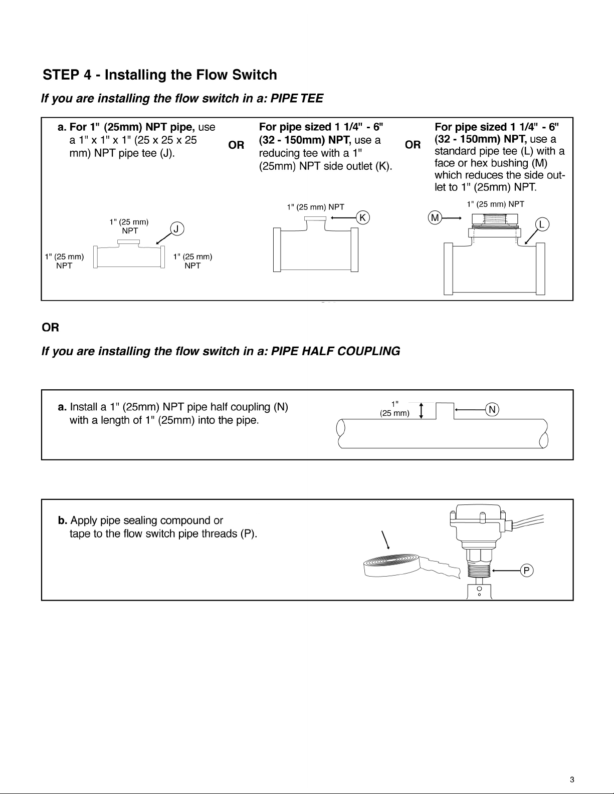
PTFE
PTFE
Page 4
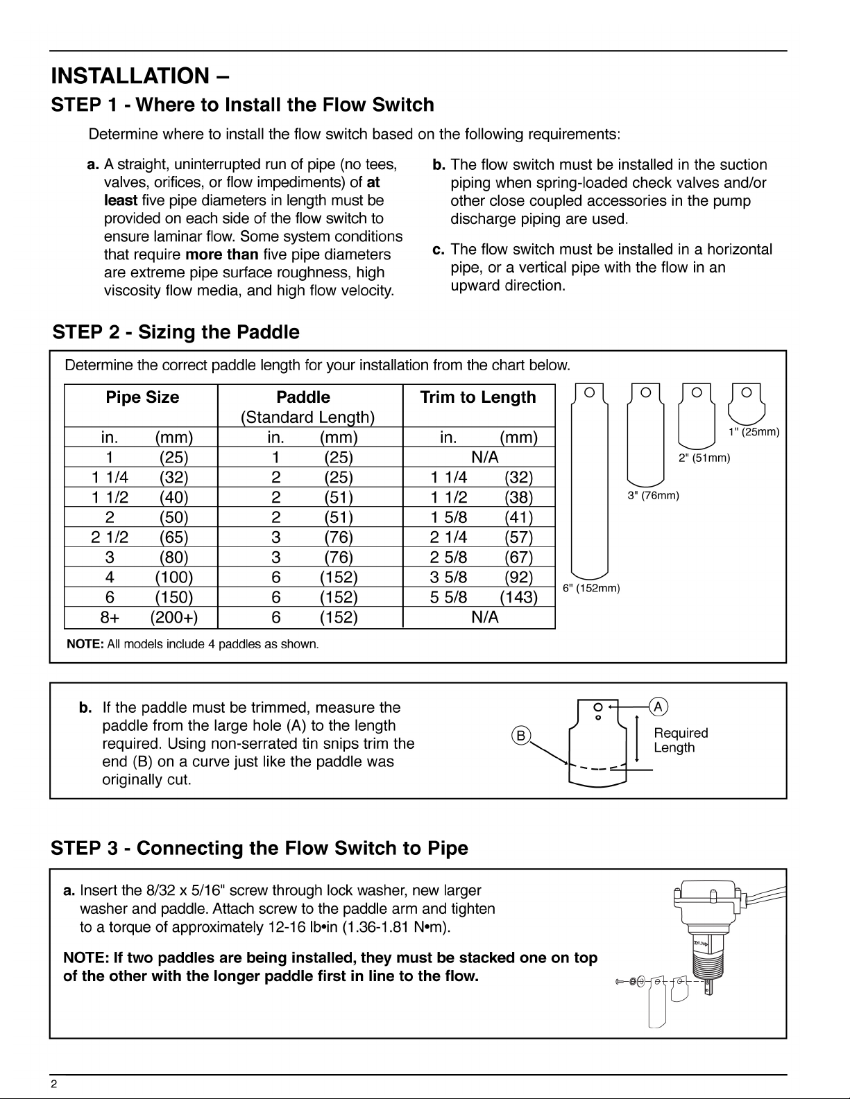
4
STEP 5 - Making Electrical Connections
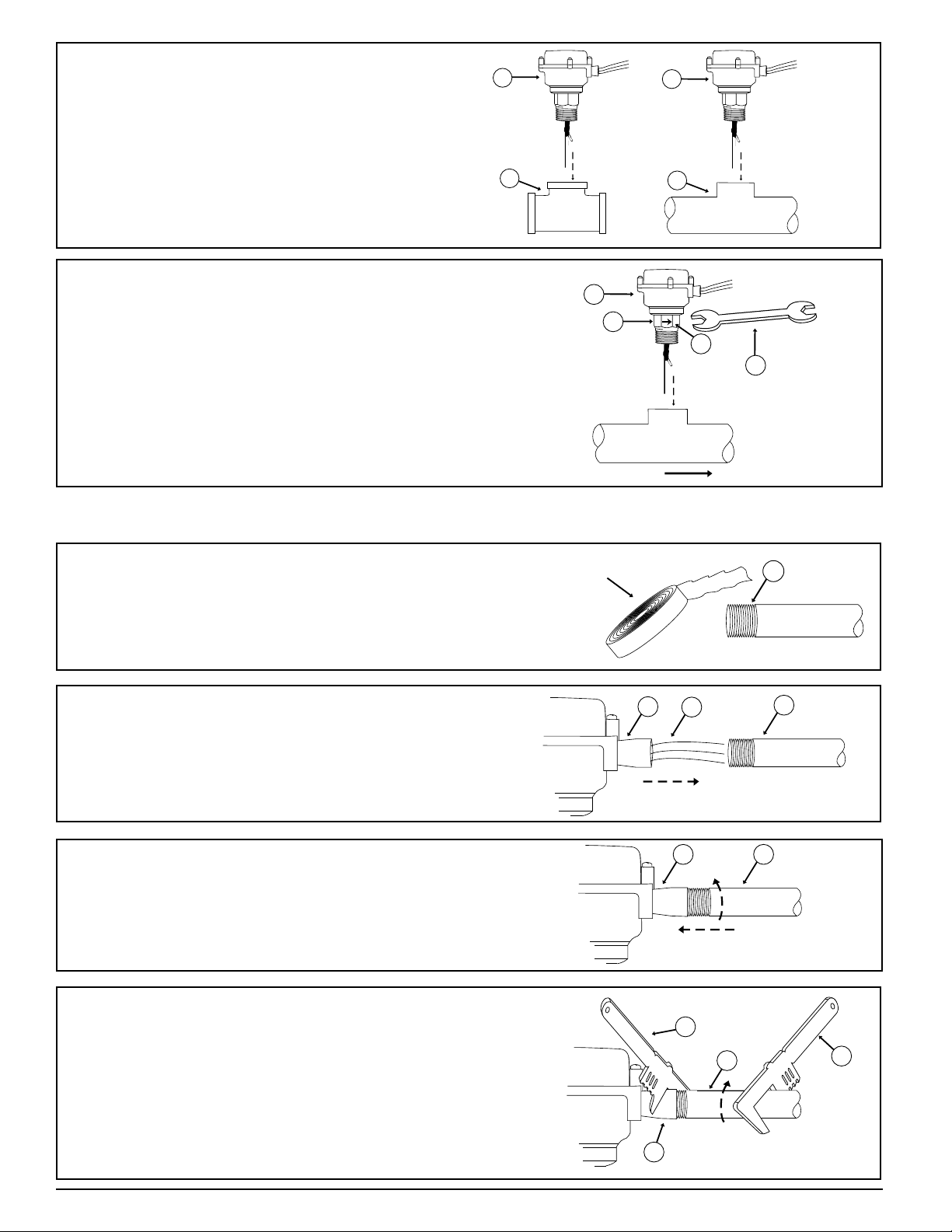
a. Apply pipe sealing compound or PTFE tape
to the threads (U) of a 1/2” (15mm) NPT pipe.
b. Insert the three (3) wires (V) extending from
the flow switch adapter (W) into the pipe (X).
V
X
W
c. Insert the pipe (X) into the adapter (W) and
finger tighten.
X
W
d. Place a pipe wrench (Y) on the pipe (X) and
another pipe wrench (Z) on the adapter (W).
While keeping the adapter (W) stationary,
tighten the pipe (X) into it.
Y
X
Z
W
c. Insert the flow switch (Q) into the pipe tee (L)
or pipe half coupling (N), depending on your
installation. Turn the flow switch (Q) two (2)
or three (3) revolutions by hand.
d. Place a 1 3/8” (35mm) open end box wrench
(R) on the hex (S) and tighten the flow switch
(Q). The final position of the flow arrow on the
side of the hex (T) must be parallel to the pipe
and in the same direction as the flow.
FLOW
Q
R
T
S
Q
Q
L
PTFE
N
U
Page 5

5
STEP 5 - continued
e. Verify that the paddle’s full range of motion
(AA) is unobstructed. Some system piping
disassembly may be required.
AA
• To prevent electrical shock, turn off the electrical power before making electrical connections.
• To prevent an electrical fire or equipment damage, electrical wiring insulation must have a
rating of 167°F (75°C) if the liquid’s temperature exceeds 180°F (82°C).
Failure to follow this warning could cause property damage, personal injury or death.
!
WARNING
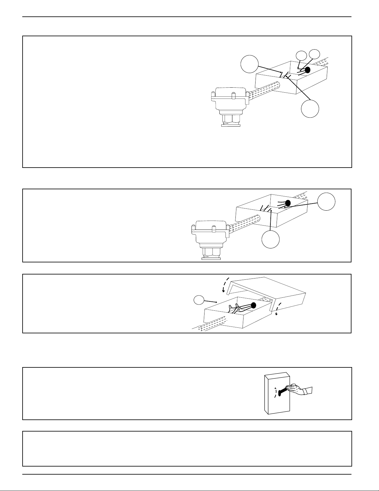
f. Insert the pipe (X) into the appropriate elec-
trical junction box (CC) and secure it.
CC
X
g. Based on the mode of operation (Flow or No Flow)
required for your application, complete the appropriate corresponding step (g.1 or g.2).
g.1.
For FLOW Mode of Operation
If the flow switch will be used to actuate a signal,
alarm, or other device when flow occurs, connect the
yellow flow switch wire (DD) to the appropriate wire
from that device (EE). Cap with a wire nut and seal
with electrical tape.
If the flow switch will also be used to actuate another
device when no flow occurs, connect the blue flow
switch wire (FF) to the appropriate wire from that
device (GG). Otherwise, cap the blue wire (FF)
with a wire nut and seal with electrical tape.
FF
blue
GG
DD
yellow
EE
COMMON
NORMALLY
OPEN
NORMALLY
CLOSED
Page 6
h. Connect the red flow switch wire (HH) to the
“Hot” power supply wire (JJ). Cap with a wire
nut and seal with electrical tape.
HH
red
JJ
“Hot”
i. Cover and properly secure the electrical
junction box (CC).
CC
a. Turn on the electrical power to the flow switch.
Initiate flow through the flow switch.
OFF
ON
b. Observe the device being activated by the flow switch, or measure the flow rate
to determine if the flow switch is activating when desired. If the flow switch isn ’t
activating when desired, follow Step 7 to adjust the sensitivity .
STEP 6 - Testing
6
For all installations
STEP 5 - continued
g.2. For NO FLOW Mode of Operation
If the flow switch will be used to actuate a signal,
alarm, or other device when no flow occurs, connect
the blue flow switch wire (FF) to the appropriate wire
from that device (EE). Cap with a wire nut and seal
with electrical tape.
If the flow switch will also be used to actuate another
device when flow occurs, connect the yellow flow
switch wire (DD) to the appropriate wire from that
device (GG). Otherwise, cap the yellow wire (DD)
with a wire nut and seal with electrical tape.
FF
blue
GG
DD
yellow
EE
Page 7

OFF
ON
a. Disconnect the electrical power to the flow switch.
STEP 7 - Adjusting the Flow Rate (only necessary if operation
above minimum flow velocities is required)
• To prevent electrical shock, turn off the electrical power before making electrical connections.
• To prevent electrocution, when the electrical power is connected to the flow switch, do not
touch the terminals, or the red, blue or yellow flow switch wires.
Failure to follow this warning could cause property damage, personal injury or death.
!
WARNING
7
KK
LL x 4
MM
b. Using a flathead screwdriver (KK), unscrew the four (4)
cover screws (LL) and remove the cover (MM).
NN
COMMON
NORMALLY
OPEN
NORMALLY
CLOSED
c. Using a flathead screwdriver, turn the adjusting
screw (NN) several turns clockwise.
LL x 4
MM
S
d. Place the cover (MM) on the flow switch (S)
and insert the four (4) cover screws (LL).
PP
LL x 4
e. Using a torque screwdriver (PP), tighten the four (4)
cover screws (LL) to a torque of 10 lb. •in (1.13 N•m).
Page 8

Xylem Inc.
8200 N. Austin Avenue
Morton Grove, Illinois 60053
Phone: (847) 966-3700
Fax: (847) 965-8379
www.xyleminc.com/brands/mcdonnellmiller
McDonnell & Miller is a trademark of Xylem Inc. or one of its subsidiaries.
 Loading...