

INSTRUCTION MANUAL
MM-284D
Operation
The Ser
ies PSE-800 probe type LWCO’s provide
protection against low water conditions for residential
and commercial steam boiler applications. The control
uses patented technology to monitor changes in
water conductivity. When defined parameters are
exceeded, the new PSE-800 makes a decision to
shut the burner off based on the volatility/variability
SPECIFICA
A
utomatic reset after power outage
All models include a provision for adding an alarm or automatic
water feeder.
30 second Delay on Make (DOM)
10 second Delay on Break (DOB)
Contr
T
T
Humidity: 85% (non-condensing)
ol Unit
emperature Ratings:
emperature:
Storage: -40˚F to 135˚F (-40˚C to 57˚C)
Ambient: 32 F to 120 F (0 C to 4 C)
TIONS
oo
o
o
9
of the resistance readings. This new patented technology
provides the best protection possible without turning
off the boiler unless a low water condition exists. As
an added measure of safety, the control will turn off
the boiler if it recognizes an out-of-water condition
when the sensitivity threshold is exceeded.
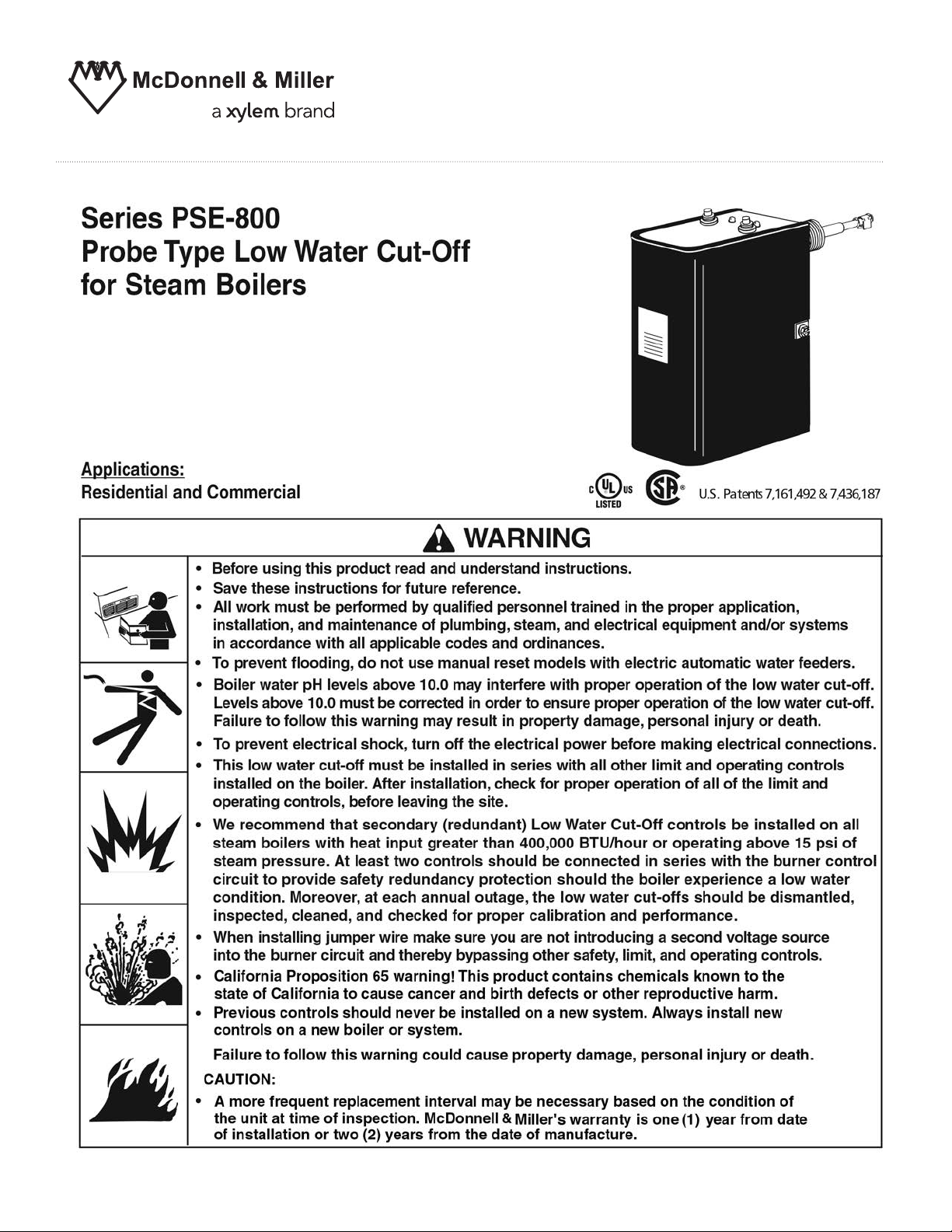
Green
(Power On)
Red
(Low Water)
obe Specifications
Pr
Maxim
Pr
HZ: 50/60
Contr
1.7VA @ 24VAC
3.6VA @ 120VAC
Electrical Enclosure Rating: NEMA 1 General Purpose
um Steam Pressure: 15 psi (1.0 kg/cm
obe Sensitivity: 7,000 ohm
Model
PSE-802-24
PSE-802-U-24
PSE-802-RX2-24
PSE-801-120
PSE-801-U-120
ol Power Consumption:
Control Voltage Motor Switch Rating
24 VAC N/A 50VA
120 VAC 7.5 FLA 43.2 LRA 125VA
2
)
Pilot Rating
2
INST
T
ALLATION
OOLS NEEDED:
One (1) flathead screwdriver, and one (1) pipe wrench.
For Remote Installations a level and power drill will be required.
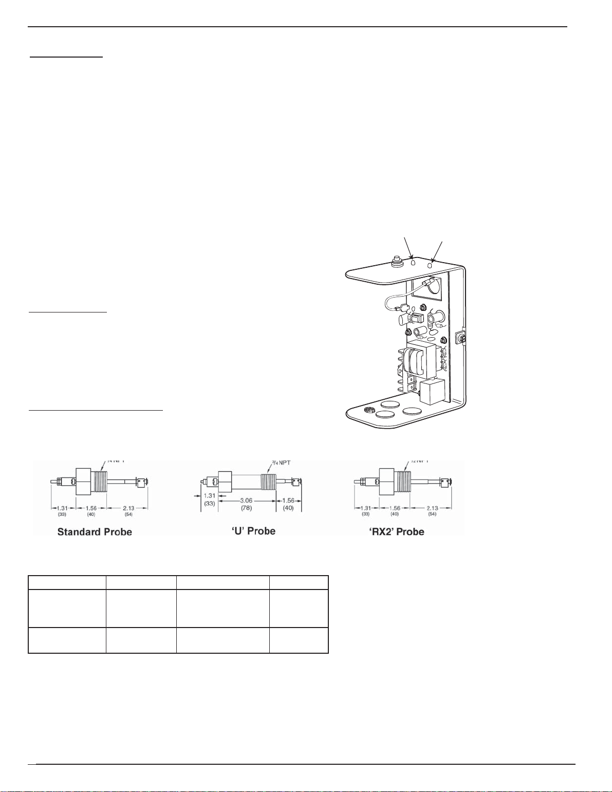
STEP 1 - Locating and Installing the Pr
a. Based on the f
For all Applications:
1. Refer to boiler manufacturers instructions to
determine suitable tapping for the probe.
2. Make sure probe is installed above minimum
safe water line as determined by the boiler
manufacturer.
3. Make sure that ends and sides of the probe
are at least 1/4” (6.4mm) from all internal
metal surfaces.
4. sure the probe is positioned to shut off
Make
the boiler before the water level falls below
the lowest visible part of the gauge
b. Sparingly, apply pipe sealant to the ext
threads (D) of the (A).
ollowing criteria locate a suitable position for the probe:
glass.
ernal
probe
obe
4
A
1/4"
3
(6mm)
1
1/4"
(6mm)
Minimum Safe
Water Level
(May vary
by boiler
manufacturer)
A
D
Control
Steam
Boiler
Probe
IMPORTANT: Do not use tape. Only use
04&%
pipe sealant.
c. Using a wrench, tighten the probe (A) into the
tapped connection (E) that w
as determined in Step
1 of these instructions. Tighten to 47 ft•lb (64 N•m).
NOTE: Be sure to align the probe so that the
mounting scre
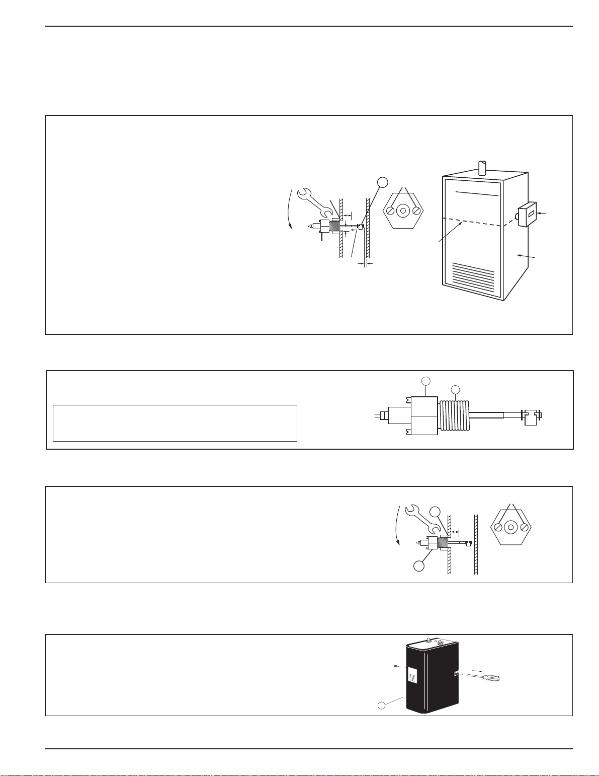
STEP 2 - Installing Contr
ws (F) are in a horizontal position.
ol Box
a. Using a flathead screwdriver, loosen the two (2) screws
that secure the cover (G) to the control about 1-1/2
turns and remove cover.
F
E
A
G
3


STEP 4 - Contr
or all wire connections to the terminal block (M).
d. F
ol Wiring (continued)
1.Strip about 1/3" (8.5 mm) of insulation from the wire.
2.Loosen the terminal screw (N) but DO NOT
REMOVE. Move the wire clamping plate (P) back until the
plate touches the back side of the screw head.
3.Insert the stripped end of the wire under the wire clamping
plate (P) and securely tighten the terminal screw (N).
PSE-802 using Harness Connection
Connect plug (A) of wir
Wiring harness is pr
Do not use f
receptacle solder connections.
Check to make sure factory supplied jumper is installed
between terminals (H) and (C).
ing harness to receptacle (B).
TE
NO
ovided by boiler manufacturer.
UTION
CA
!
orce to insert plug. This may damage
N
P
M
B
A
PSE-802 using
Connect neutral wire (A) of 24 volt circuit to terminal (N).
•
Terminal Connections
• Connect hot wire (B) of 24 volt circuit to terminal (H).
• Connect wire (C) from beginning of Burner circuit
(thermostat, gas valve, limits, etc.) to terminal (B).
• Connect wire (D) from end of Burner circuit to terminal (N).
• Make sure factory provided jumper bar is connected to
terminal (H) and (C).
PSE-801 with 120
•
Connect Hot wire (A) of 120 volt circuit to terminal (H).
Volt Burner Circuit
• Connect Neutral wire (B) of 120 volt circuit to terminal (N).
• Connect wire (C) from beginning of Burner circuit (thermostat,
gas valve, limits, etc.) to terminal (B).
• Connect wire (D) from end of Burner circuit to terminal (N).
• Connect jumper wire (E) to terminals (H) and (C).
PSE-801 with 24
•
Connect hot wire (A) of 120 volt circuit to terminal (H) and
Volt Burner Circuit
transformer terminal (L1).
• Connect neutral wire ‘B’ of 120 volt circuit to terminal (N) and
transformer terminal (L2).
• Connect wire (C) from beginning of Burner circuit
(thermostat, gas valve, limits, etc.) to terminal (B).
• Connect wire (D) from end of Burner circuit to transformer
terminal (T2).
• Connect wire (E) from transformer terminal (T1) to
terminal (C).
120 V
CIRCUIT
OLT
120 V
CIRCUIT
24 V
OLT
POWER
CIRCUIT
OLT
B
B
A
H
N
A
H
N
E
B
JUMPER
BAR
N H C W B
A
D
N H C W B
B
D
N H C W B
1
L
2
L
24 V
TRANSFORMER
(BY OTHERS)
NH
OLT
B
URNER
CIRCUIT
URNER
B
CIRCUIT
1
T
B
T
2
CIRCUIT
E
E
URNER
D
C
C
C
INST
ALLATION COMPLETE
6


Xylem Inc.
8200 N. Austin Avenue
Morton Grove, Illinois 60053
Phone: (847) 966-3700
Fax: (847) 965-8379
www.mcdonnellmiller.com
McDonnell & Miller is a trademark of Xylem Inc. or one of its subsidiaries.
© 2014 Xylem Inc. MM-284D January 2014 Part No. 211630
 Loading...